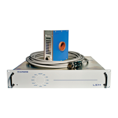
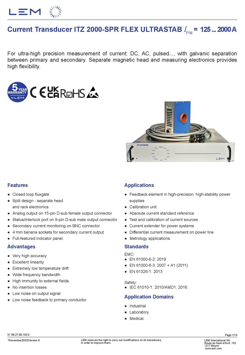
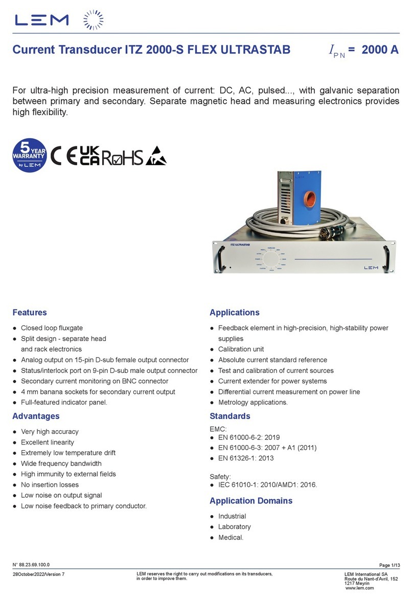
LEM ITZ 5000-S FLEX ULTRASTAB User manual

Page 1/15
28October2022/Version 7
LEM reserves the right to carry out modications on its transducers,
in order to improve them.
LEM International SA
Route du Nant-d’Avril, 152
1217 Meyrin
www.lem.com
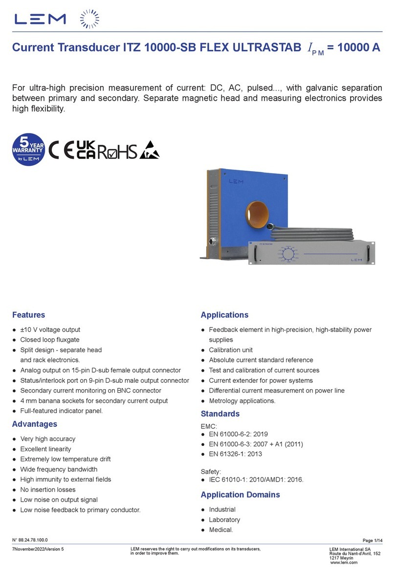
Current Transducer ITZ 5000-S FLEX ULTRASTAB IP N = 5000 A
N° 88.23.75.100.0
For ultra-high precision measurement of current: DC, AC, pulsed..., with galvanic separation
between primary and secondary. Separate magnetic head and measuring electronics provides
high exibility.
Features
● Closed loop uxgate
●Split design - separate head
and rack electronics
●Analog output on 15-pin D-sub female output connector
●Status/interlock port on 9-pin D-sub male output connector
●Secondary current monitoring on BNC connector
●4 mm banana sockets for secondary current output
●Full-featured indicator panel.
Advantages
●Very high accuracy
● Excellent linearity
● Extremely low temperature drift
●Wide frequency bandwidth
● High immunity to external elds
●No insertion losses
●Low noise on output signal
●Low noise feedback to primary conductor.
Applications
●Feedback element in high-precision, high-stability power
supplies
●Calibration unit
●Absolute current standard reference
●Test and calibration of current sources
● Current extender for power systems
● Dierential current measurement on power line
●Metrology applications.
Standards
EMC:
●EN 61000-6-2: 2019
●EN 61000-6-3: 2007 + A1 (2011)
●EN 61326-1: 2013
Safety:
●IEC 61010-1: 2010/AMD1: 2016.
Application Domains
●Industrial
●Laboratory
●Medical.

Page 2/15
28October2022/Version 7
LEM reserves the right to carry out modications on its transducers,
in order to improve them.
LEM International SA
Route du Nant-d’Avril, 152
1217 Meyrin
www.lem.com
ITZ 5000-S FLEX ULTRASTAB
Safety
This transducer must be used in limited-energy secondary circuits according to IEC 61010-1.
⚠
Caution
This transducer must be used in electric/electronic equipment with respect to applicable standards and safety requirements in
accordance with the manufacturer’s operating instructions.
If the device is used in a way that is not specied by the manufacturer, the protection provided by the device may be
compromised. Always inspect the electronics unit and connecting cable before using this product and do not use it if damaged.
Mounting assembly shall guarantee the maximum primary conductor temperature, fulll clearance and creepage distance,
minimize electric and magnetic coupling.
Caution, risk of electrical shock
Use caution during installation and use of this product; certain parts of the module can carry hazardous voltages and high currents
(e.g. primary conductor).
Ignoring this warning can lead to injury and or/or cause serious damage.
De-energize all circuits and hazardous live parts before installing the product.
All installations, servicing operations and use must be carried out by trained and qualied personnel practicing applicable safety
precautions.
This transducer is a built-in device, no maintenance required; cleaning by dry compressed air is authorized.
This transducer is a build-in device, whose hazardous live parts must be inaccessible after installation.
This transducer must be mounted in a suitable end-enclosure.
Besides make sure to have a distance of minimum 30 mm between the primary conductor (return bar) and the transducer and
other neighboring components.
Main supply must be able to be disconnected.
Always inspect the current transducer for damage before using this product.
Never connect or disconnect the power while the primary circuit is connected to live parts.
Never connect the output to any equipment with a common mode voltage to earth greater than 30 V.
Always wear protective clothing and gloves if hazardous live parts are present in the installation where the measurement is carried
out.
Safe and trouble-free operation of this transducer can only be guaranteed if transport, storage and installation are carried out
correctly and are carried out with care.
The current transducer shall not be opened or modied.
If not working, the current transducer shall be replaced by an equivalent device.
In case of main supply cable replacement, make sure to use similar cable to guaranty the safety; please refer to the user
manual for more information.
ESD susceptibility
The product is susceptible to ESD damage if secondary connectors pins are touched without being properly grounded.
Remark
Installation of the transducer must be done unless otherwise specied on the datasheet, according to LEM
Transducer Generic Mounting Rules. Please refer to LEM document N°ANE120504 available on our Web site:
https://www.lem.com/en/le/3137/download/.

Page 3/15
28October2022/Version 7
LEM reserves the right to carry out modications on its transducers,
in order to improve them.
LEM International SA
Route du Nant-d’Avril, 152
1217 Meyrin
www.lem.com
ITZ 5000-S FLEX ULTRASTAB
Mains INPUT
Parameter Symbol Unit Value Comment
Mains input voltage UCV100-240 V AC (±10 %) IEC-type inlet socket OVCII and PD2
Mains input frequency fHz 50/60
Fuses At 2.5/240 V AC Internal fuses, not user-replaceable
Power consumption PCW
76
ITZ 2000-S; ITZ 2000-SB;
ITZ 2000-SPR;
ITZ 2000-SBPR;
ITZ 5000-S; ITZ 5000-SB
163 ITZ 6100-S
137 ITZ 10000-S; ITZ 10000-SB
202 ITZ 16000-S; ITZ 16000-SB
300 ITZ 24000-S; ITZ 24000-SB
Insulation coordination
Parameter Symbol Unit Value Comment
Rated insulation RMS voltage, basic insulation UNm V4000
IEC 61010-1 conditions
- over voltage cat III
- pollution degree 2
Rated insulation RMS voltage, reinforced insulation UNm V2000
IEC 61010-1 conditions
- over voltage cat III
- pollution degree 2
RMS voltage for AC insulation test, 50/60 Hz, 1 min UdkV 16.2
Impulse withstand voltage 1.2/50 µs UNi kV 29.8
Clearance (pri. - sec.) dCI mm 40 Shortest distance through
air
Creepage distance (pri. - sec.) dCp mm 40 Shortest path along device
body
Comparative tracking index CTI 100
Environmental and mechanical characteristics
Parameter Symbol Unit Min Typ Max Comment
Ambient operating temperature HEAD TA°C 055
Ambient operating temperature ELECTRONICS TA°C 10 40
Ambient storage temperature HEAD and
ELECTRONICS TA st °C −20 85
Maximum primary conductor temperature TB max °C 100
Relative humidity RH %20 80 Non-condensing
Dimensions ELECTRONICS mm 482 × 88 × 430
see drawing (page 15)
Dimensions HEAD see drawing (page 15)
Altitude m2000 1)
Mass rack electronics mkg 8.4
Mass head mkg 17
Note: 1) Insulation coordination at 2000 m.

Page 4/15
28October2022/Version 7
LEM reserves the right to carry out modications on its transducers,
in order to improve them.
LEM International SA
Route du Nant-d’Avril, 152
1217 Meyrin
www.lem.com
ITZ 5000-S FLEX ULTRASTAB
Electrical data
At TA= 25 °C unless otherwise noted.
Parameter Symbol Unit Min Typ Max Comment
Primary continuous direct current IP N DC A−5000 5000
Primary nominal RMS current 1) IP N A5000 See graphs on
page 5
Primary current, measuring range IP M A−7072 7072 See graphs on
page 6
Measuring resistance RMΩ01.5
Secondary current ISA−2 2
Turns ratio NP/NS1:2500
Resistance of secondary winding RSΩ4.3
Primary withstand peak current (max) 1) ÎP max kA 25
Mains supply RMS voltage V100 240
Rated power supply frequency fHz 50/60
Power consumption IP= 0 A
@ Mains supply = 230 V RMS PC
W
VA
38
82
Average
Peak
Power consumption IP = IP N DC (5000 A)
@ Mains supply = 230 V RMS PC
W
VA
76
116
Average
Peak
RMS noise current 0 … 10 Hz 2)
Ino ppm
0.02
RMS noise current 0 … 10 kHz 2) 2.5
RMS noise current 0 … 100 kHz 2) 20
Re-injected RMS noise on primary bus bar
0 ... 100 kHz µV 10
Electrical oset current 3) IO E ppm −2 2
Temperature coecient of IO E
3) TCIO E ppm/K −0.1 0.1 10 °C .. 40 °C
Oset stability 3) ppm/month −1 1
Linearity error 3) εLppm −3 3
Delay time @ 90 % of the nal output
value IP N DC step tD 90 µs 1With a
di/dt ≥ 20 A/µs
Frequency bandwidth (± 3 dB) BW kHz 080
Small-signal
bandwidth,
1 % of IP N DC
di/dt accurately followed di/dtA/µs 20
Notes: 1) With cable length < 12 meters (see graphs page 4)
2) Single pulse of 100 ms only, not AC. The transducer may require a few seconds to return to
normal operation when autoreset system is running
3) All ppm gures refer to full-scale which corresponds to a secondary current (IS) output of 2 A.

Page 5/15
28October2022/Version 7
LEM reserves the right to carry out modications on its transducers,
in order to improve them.
LEM International SA
Route du Nant-d’Avril, 152
1217 Meyrin
www.lem.com
ITZ 5000-S FLEX ULTRASTAB
3000
3500
4000
4500
5000
5500
0 5 10 15 20 25 30 35 40 45 50
RM = 0.5 ΩRM = 1 ΩRM = 1.5 Ω
Cable length (m)
*: provided by LEM
Primary nominal RMS current versus Cable* length TA= 0 to 55 °C
Primary nominal RMS current (A)
Primary nominal RMS current versus cable length
Primary nominal RMS current versus cable resistance
3000
3500
4000
4500
5000
5500
0 0.5 1 1.5 2 2.5 3 3.5 4 4.5 5
RM = 0.5 ΩRM = 1 ΩRM = 1.5 Ω
Primary nominal RMS current versus Cable* resistance TA= 0 to 55 °C
Cable resistance (Ω)
Primary nominal RMS current (A)
*: Outward and Return paths included

Page 6/15
28October2022/Version 7
LEM reserves the right to carry out modications on its transducers,
in order to improve them.
LEM International SA
Route du Nant-d’Avril, 152
1217 Meyrin
www.lem.com
ITZ 5000-S FLEX ULTRASTAB
Primary current measuring range versus cable length
Primary current measuring range versus cable resistance
-8000
-7000
-6000
-5000
-4000
-3000
-2000
-1000
0
1000
2000
3000
4000
5000
6000
7000
8000
0 5 10 15 20 25 30 35 40 45 50
RM = 0.5 Ω
RM = 1 Ω
RM = 1.5 Ω
Cable length (m)
*: provided by LEM
Primary current measuring range versus Cable* length TA= 0 to 55 °C
IPM +
IPM -
Primary current measuring range (A)
-8000
-7000
-6000
-5000
-4000
-3000
-2000
-1000
0
1000
2000
3000
4000
5000
6000
7000
8000
0 0.5 1 1.5 2 2.5 3 3.5 4 4.5 5
RM = 0.5 Ω
RM = 1 Ω
RM = 1.5 Ω
Primary current measuring range versus Cable* resistance TA= 0 to 55 °C
Cable resistance (Ω)
Primary current measuring range (A)
*: Outward and Return paths included
IPM +
IPM -

Page 7/15
28October2022/Version 7
LEM reserves the right to carry out modications on its transducers,
in order to improve them.
LEM International SA
Route du Nant-d’Avril, 152
1217 Meyrin
www.lem.com
ITZ 5000-S FLEX ULTRASTAB
Typical power consumption
0
10
20
30
40
50
60
70
80
90
-6000 -5000 -4000 -3000 -2000 -1000 01000 2000 3000 4000 5000 6000
Primary current IP(A)
Typical power consumption (W)
Typical power consumption vs primary current TA= 25 °C

Page 8/15
28October2022/Version 7
LEM reserves the right to carry out modications on its transducers,
in order to improve them.
LEM International SA
Route du Nant-d’Avril, 152
1217 Meyrin
www.lem.com
ITZ 5000-S FLEX ULTRASTAB
System overview
Front panel indicators
When the mains supply voltage is set up, the rack electronics starts and initializes itself. After this process, the LEDs POWER,
STATUS and 5000 A light up.
The LEDs present on this panel display information about conditions which aect the operation of the transducer.
They are dened in the following table:
LED Description
POWER (blue LED) This LED is lit when the mains supply voltage is present
ACTIVE (yellow LED) This LED is lit when IP is higher than approximately 1 %
of IP N DC
HIGH IP(yellow LED) This LED is lit when IP is higher than approximately 105 %
of IP N DC
OVERLOAD (red LED) This LED is lit when the transducer head saturates due to
excessive primary current.
600 A ... 24000 A (yellow LED)
These LEDs are lit when a transducer head with the
corresponding full-scale range is connected to the rack
electronics. For ITZ 5000-S, only LED 5000 A is lit, and the
others may be ignored.
CUSTOM (yellow LED) Reserved for a custom head conguration.
STATUS (green LED) This LED is lit when the unit status is OK (Normal operation).
POWER
2000A
16000A
OVERLOAD
600A
10000A
5000A
24000A
HIGH Ip
ACTIVE
STATUS
CUSTOM
Front Panel Indicators
0.000
U
in
IMPORTANT :
The GREEN secondary current path must be
closed at all times when MAINS power is
applied.
If only one of the two current output ports is in
use, the other MUST be shorted with the
appropriate shorting plug.
Transducer Head
Mains
100-240 V
50/60Hz
ITZ Rack Electronics
Power
Amplifier
I
s
.out
Is.return
0.1 Ω
Analog Out Connector
RM
Monitor
Connector
±1 V full-scale
DMM
0.000
Iin
DMM
Status/
Interlock
Connector
4 mm
Banana
Output
Ferrite core
Digital
Multimeter
Digital
Multimeter

Page 9/15
28October2022/Version 7
LEM reserves the right to carry out modications on its transducers,
in order to improve them.
LEM International SA
Route du Nant-d’Avril, 152
1217 Meyrin
www.lem.com
ITZ 5000-S FLEX ULTRASTAB
Back panel
Reference Description
1IEC power inlet: This connector accepts a standard IEC power cord (supplied)
2Type / Serial number plate. Three individual S/Ns may be listed here: One for the ITZ electronics, one for
the matching head and one (optional) for the installed voltage output module
3Transducer head: Connection to the transducer head
4Analog out: Output connection to a DMM or other equipment, 15-pin D-Sub female UNC 4-40 screw lock
5Current ±: Secondary current output
6Monitor: Voltage output with a buered replica of the secondary current
7Status/Interlock signal outputs, 9-pin D-Sub male UNC 4-40 screw lock
8Option A+B: These positions are for future expansion or customization (not used)
28 3
1
7 6 5 4
LEMInternational SA
Route du
Nant-d’Avril, 152
1217 Meyrin
LEM International SA
Route du
Nant-d’Avril, 152
1217 Meyrin
92.47.08.233.0_03
Labelling
ITZ Ultrastab
TYPE: ITZ Ultrastab HEAD S/N:
VOM S/N:
UNIT S/N:
Unplug mains cable
before removing cover
MAINS INPUT
100-240VAC
50/60 HZ
300W (MAX)
OPTION A OPTION B
TRANSDUCER
HEAD
ANALOG OUT
+ CURRENT -MONITORSTATUS
Do not apply current to
the transducerhead
before MAINS INPUT is
ON
Do not connect or
disconect the
transducerhead
while MAINS INPUT is
ON
Refer to cung drawing 92.31.08.266.0
MARKING
ITZ
1 / 1
92.47.08.233.0 04
A4 1:1 07.26.2022 pia
01 01.06.2020 Add new LEM logo G1933101 PMo
02 04.20.2020 Change LEM Switzerland SA in LEM International SA G2011101 PMo
03 06.06.2022 Add UKCA and DANGER LOGO, and LEM address G2204218 pia
04 07.26.2022 Adjust UKCA marking position G2204218 pia

Page 10/15
28October2022/Version 7
LEM reserves the right to carry out modications on its transducers,
in order to improve them.
LEM International SA
Route du Nant-d’Avril, 152
1217 Meyrin
www.lem.com
ITZ 5000-S FLEX ULTRASTAB
Status /Interlock Port - electrical specication
All signals on the Status/Interlock port are optically isolated, Photocouplers type, oating Collector and Emitter. Four signals are
present on the port, each having two dedicated oating pins in the SUBD9 Male connector:
. Collector (C)
and
. Emitter (E)
Status /Interlock port wiring
Depending on how each signal is wired, it can be “Active Low” or “Active High” as shown below:
In the Diagram A Active Low Output, the output signal Uout switches to GND when the corresponding LED is ON.
In the Diagram B Active High Output, the output signal Uout switches to +UCwhen the corresponding LED is ON.
When the output signal Uout is switched to GND, its value is lower than 0.2 V.
When the output signal Uout is switched to +UC, its value is equal to +UC.
1
6
SUBD9 Pin
OVERLOAD
SUBD9 Pin
2
7
SUBD9 Pin
High Ip
SUBD9 Pin
3
8
SUBD9 Pin
ACTIVE
SUBD9 Pin
4
9
SUBD9 Pin
STATUS
SUBD9 Pin
5
SUBD9 Pin
Not Connected
C
E
C
E
E
E
C
C
SUBD9 Pin
SUBD9 Pin
C
E
DC
Power
Supply
Status/Interlock port Wiring
SUBD9 Pin
SUBD9 Pin
C
E
U
out
U
out
DC
Power
Supply
+U
C
+U
C
Active Low Output Active High Output
R
R
Diagram A Diagram B

Page 11/15
28October2022/Version 7
LEM reserves the right to carry out modications on its transducers,
in order to improve them.
LEM International SA
Route du Nant-d’Avril, 152
1217 Meyrin
www.lem.com
ITZ 5000-S FLEX ULTRASTAB
In case diagram A, the following table shows how each individual output signal acts:
Output signal Uout Description
OVERLOAD
< 0.2 V The transducer head is saturated due to excessive primary current
+UCThe transducer head is not saturated
High IP
< 0.2 V The primary current is higher than 105 % of nominal full-scale output
+UCThe primary current is lower than 105 % of nominal full-scale output
ACTIVE
< 0.2 V The primary current is higher than approximately 1 % of nominal full-scale output
+UCThe primary current is lower than approximately 1 % of nominal full-scale output
STATUS
< 0.2 V When the unit status is OK (Normal operation)
+UC
When the unit status is not OK (Supply fault, over-temperature conditions and Current
overloads or No detected head)
In case diagram B, the following table shows how each individual output signal acts:
Output signal Uout Description
OVERLOAD
+UCThe transducer head is saturated due to excessive primary current
< 0.2 V The transducer head is not saturated
High IP
+UCThe primary current is higher than 105 % of nominal full-scale output
< 0.2 V The primary current is lower than 105 % of nominal full-scale output
ACTIVE
+UCThe primary current is higher than approximately 1 % of nominal full-scale output
< 0.2 V The primary current is lower than approximately 1 % of nominal full-scale output
STATUS
+UCWhen the unit status is OK (Normal operation)
< 0.2 V When the unit status is not OK (Supply fault, over-temperature conditions and Current
overloads or No detected head)
The power supply voltage +UCmust be between 4 V and 60 V DC and the resistor value must be chosen between a minimum
value Rmin and a maximum value Rmax calculated by using the following equations:
Some recommended standard values of Rare given in the following table:
Power supply voltage +UCRmin (kΩ) Rmax (kΩ) RStandards values ±5 %
5 V 1.5 31.8 kΩ or 2.2 kΩ
12 V 3.5 74.7 kΩ or 6.8 kΩ
24 V 714 10 kΩ or 12 kΩ
Absolute maximum ratings
Parameter Symbol Specication Unit
Power supply voltage +UC60 V
Maximum Collector-Emitter Voltage, O-state UC E o max 60 V
Maximum reverse Collector-Emitter Voltage, O-state UC E o max 5 V
Maximum Collector-Emitter Current, On-state IC E ON max 10 mA
Stresses beyond those listed under absolute maximum ratings may cause permanent damage to the status/interlock signal outputs.
R
min
(k
ΩΩ
)
=
+
U
C
U
C
31.7
.4
and
R
(k )
=
+
max

Page 12/15
28October2022/Version 7
LEM reserves the right to carry out modications on its transducers,
in order to improve them.
LEM International SA
Route du Nant-d’Avril, 152
1217 Meyrin
www.lem.com
ITZ 5000-S FLEX ULTRASTAB
Sweep function during overload status
The overload occurs when the primary current IP exceeds a trip level such that the uxgate detector becomes completely saturated
and, consequently, the transducer will switch from normal operation to overload mode.
This trip level is guaranteed to be greater than 110 % of IP N DC and its actual value depends on operating conditions such as
temperature and measuring resistance.
When this happens, the ITZ rack electronics will automatically begin to sweep in order to lock on to the primary current again and
the measuring can resume when the primary current returns in the nominal range between −IP N DC and +IP N DC.
In sweep mode, the secondary current will be a slope between −2 A and +2 A.
Thermal protection
The ITZ 5000-S has thermal shutdown circuitry that protects the electronics from damage.
The thermal protection circuitry disables the measuring circuit when the rack electronics temperature reaches approximately
65 °C and allows the transducer to cool. When this occurs, the status LED is switched o.
When the rack electronics temperature cools to approximately 60 °C, the measuring circuit is automatically re-enabled and the
status LED is again lit.
Over current protection - Electrical specications
The over current occurs when the primary current exceeds 120 % of IP N DC.
To detect the over current with primary AC, the secondary current is full-wave rectied and is time-averaged by a low-pass lter.
Depending on the frequency range of the primary current, two cases appear:
- Low frequency range: DC – 1.6 Hz (over current slow)
In this case, the over current trip level is set to 120 % of IP N DC.
The secondary current is tracked until the primary AC peak exceeds this trip level. Then, the rack electronics shut down the
measuring circuit and wait until the primary AC peak becomes lower than the set trip level.
- High frequency range: 1.6 Hz – 1.6 KHz (over current fast)
In this case, the over current trip level is set to 160 % of IP N DC.
The secondary current is tracked until the primary AC peak exceeds this trip level. Then, the rack electronics shut down the
measuring circuit and wait until the primary AC peak becomes lower than the set trip level.
The frequency response characteristics of the over current trip level with a sine-wave primary AC is illustrated by the following
curve:
0
50
100
150
200
250
300
350
400
450
0.0 0.1 1.0 10.0 100.0 1000.0 10000.0
Frequency (Hz)
(DC)
Typical over current trip level (% of
IPN
DC)
Typical over current trip level vs frequency TA= 25 °C

Page 13/15
28October2022/Version 7
LEM reserves the right to carry out modications on its transducers,
in order to improve them.
LEM International SA
Route du Nant-d’Avril, 152
1217 Meyrin
www.lem.com
ITZ 5000-S FLEX ULTRASTAB
The table shown below summarizes various frequency values and the typical value of over current trip level to detect over current
state:
Primary current frequency (Hz) Typical over current trip level to detect over current state
DC (0 Hz)) 120 % of IP N DC
1130 % of IP N DC
1.5 140 % of IP N DC
50 160 % of IP N DC
800 170 % of IP N DC
1600 186 % of IP N DC
Under these conditions:
- The signal Status (Contact between Pin 4:C and Pin 9:E) switches o, this signal becomes open (No current from collector to
emitter) to indicate that the unit is not OK.
- The status green LED located on the front panel switches o (fault state)
- The transducer is protected against damage that the over current primary AC may cause to the electronics.
The transducer will automatically starts again to work when the primary AC peak becomes lower than the trip level indicated in
the table above.
Transducer head description
Connect the transducer head to the electronics rack using the supplied transducer head cable.
The side of cable where there is the ferrite must be connected to the rack electronics.
The transducer head cable is available in three lengths: 10, 20 and 30 meters.
For more information, see section “ITZ mandatory accessories” on page 14.
Analog output connector
Normally the provided analog output cable should be used. It is also possible to congure your own output cable, bearing the
following description in mind.
The female 15-pin D-Sub connector Analog out connector contains the following signals:
1. Current return
2. Current return
3. Current return
4. No connection
5. No connection
6. Ground
7. No connection
8. No connection
9. Current out
10. Current out
11. Current out
12. No connection
13. No connection
14. No connection
15. No connection
The pins 1 to 3 are internally shorted by rack electronics. It is the same for pins 9 to 11.
Details of further considerations relating to connect the analog output connector directly to a current measuring device can be
found in the ITZ FLEX ULTRASTAB user guide.
15 9
8 1
1 8
9 15

Page 14/15
28October2022/Version 7
LEM reserves the right to carry out modications on its transducers,
in order to improve them.
LEM International SA
Route du Nant-d’Avril, 152
1217 Meyrin
www.lem.com
ITZ 5000-S FLEX ULTRASTAB
Secondary current monitoring
The rack electronics incorporates a 0.1 Ω resistance in series with the measuring resistance for the monitoring of the secondary
current.
A BNC connector located on the rear panel provides a low-precision voltage output ±1 V full-scale which indicates a secondary
current owing through the measuring resistance and the 0.1 Ω resistance.
The voltage on this connector is equal to (IP (A) × 0.1 Ω × 5) /2500 (Volt).
As one example, if IPis 5000 A, the voltage on this connector is 1 V. Similarly, if IP is −5000 A, the voltage on this connector is −1 V.
As another example, if IPis 2500 A, the voltage on this connector is 0.5 V. Similarly, if IP is −2500 A, the voltage on this connector
is −0.5 V.
Delivery package
The LEM ITZ 5000-S FLEX ULTRASTAB package contains by default:
●19-inch rack-mount ITZ FLEX ULTRASTAB electronics
●Transducer head
●European (Schuko CEE 7/7) and US/Japanese mains cables, 2 m each (with three-pole IEC C13 female connector).
●Short-plug for 4 mm banana terminals and 15-pin D-Sub short-plug for analog output connector
(back panel of electronics rack)
Mandatory accessories
The 2 following accessories have to be separately ordered as per the table hereafter, otherwise the ITZ FLEX ULTRASTAB can
not operate without them:
●Transducer head cable (interconnecting cable between transducer head and electronics rack)
●Analog output cable
ITZ mandatory accessories Available material Available length Part number
Transducer HEAD cable
Non-Halogeneous
Non-Halogeneous
Non-Halogeneous
Halogeneous
Halogeneous
Halogeneous
Halogeneous
Halogeneous
10 m
20 m
30 m
10 m
15 m
20 m
25 m
30 m
71.16.13.001.0
71.16.17.001.0
71.16.20.001.0
71.16.13.000.0
71.16.15.000.0
71.16.17.000.0
71.16.19.000.0
71.16.20.000.0
Analog output cable Non-Halogeneous 1.5 m 71.17.E7.001.0
* Other values might be possible upon request to LEM.
Optional
Calibration can be separately ordered as per the table hereafter:
● Calibration with certicate in ISO 17025 certicated laboratory
ITZ calibration (optional) Available calibration
From −5000 A to +5000 A in dierential method 5 or 11 points
or Special

Page 15/15
28October2022/Version 7
LEM reserves the right to carry out modications on its transducers,
in order to improve them.
LEM International SA
Route du Nant-d’Avril, 152
1217 Meyrin
www.lem.com
ITZ 5000-S FLEX ULTRASTAB
Dimensions - Rack electronics (in mm, general tolerance ±1.5 mm)
Dimensions - Measuring head (in mm, general tolerance ±1.5 mm)
Table of contents
Other LEM Transducer manuals

LEM
LEM ITZ 2000-SBPR FLEX ULTRASTAB User manual

LEM
LEM ITZ 2000-SPR FLEX ULTRASTAB User manual

LEM
LEM DK series User manual

LEM
LEM IT 60-S User manual

LEM
LEM ITZ 10000-SB FLEX ULTRASTAB User manual

LEM
LEM IN 100-S User manual

LEM
LEM ITZ 2000-SB FLEX ULTRASTAB User manual

LEM
LEM DVL 1500/SP8 User manual

LEM
LEM ITZ 2000-S FLEX ULTRASTAB User manual
Popular Transducer manuals by other brands

HBM
HBM S2M Series Mounting instructions

Mianyang Weibo Electronic
Mianyang Weibo Electronic WBV415S01 user manual

Thyracont
Thyracont VSM77D operating instructions

Airmar
Airmar SS422 Owner's guide and installation instructions

HBM
HBM Paceline CFT Mounting instructions

FuehlerSysteme
FuehlerSysteme RAF/A operating manual