LeMond Fitness RevMaster 15100 User manual

SERVICE MANUAL
For Lemond Exercise Bikes, Models:
15100, 15200, 15300, and15400,


Pg. 1
Table of Contents
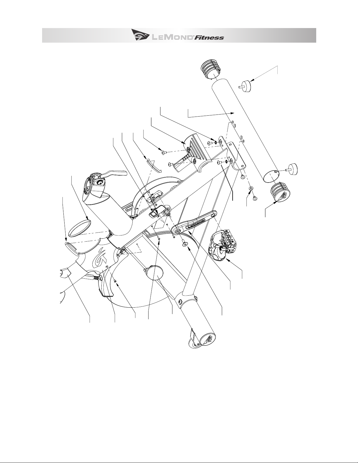
Exploded Diagrams................................................................................ 2
Tool List ..........................................................................................10
Installation Check List...........................................................................11
Stabilizer Bars.....................................................................................11
Pedals . . . . . . . . . . . . . . . . . . . . . . . . . . . . . . . . . . . . . . . . . . . . . . . . . . . . . . . . . . . . . . . . . . . . . . . . . . . . . . . . . . . . . . . . . . . . 11
Handlebar . . . . . . . . . . . . . . . . . . . . . . . . . . . . . . . . . . . . . . . . . . . . . . . . . . . . . . . . . . . . . . . . . . . . . . . . . . . . . . . . . . . . . . . . 11
Seat Slider ........................................................................................11
Water Bottle Holder ...............................................................................11
Maintenance Schedule...........................................................................12
Troubleshooting ..................................................................................13
Disassembly / Adjustment / Assembly ...........................................................15
Handlebar . . . . . . . . . . . . . . . . . . . . . . . . . . . . . . . . . . . . . . . . . . . . . . . . . . . . . . . . . . . . . . . . . . . . . . . . . . . . . . . . . . . . . . . . 15
Pedals . . . . . . . . . . . . . . . . . . . . . . . . . . . . . . . . . . . . . . . . . . . . . . . . . . . . . . . . . . . . . . . . . . . . . . . . . . . . . . . . . . . . . . . . . . . . 16
Crank Arms . . . . . . . . . . . . . . . . . . . . . . . . . . . . . . . . . . . . . . . . . . . . . . . . . . . . . . . . . . . . . . . . . . . . . . . . . . . . . . . . . . . . . . . 17
Belt Cover ........................................................................................18
Drive Belt .........................................................................................19
Drive Belt Tension ......................................................................................... 20
Bottom Bracket ...................................................................................21
Flywheel..........................................................................................22
Pillow Block ................................................................................................23
Brake Assembly ..................................................................................24
Fender...........................................................................................25
Brake Pad..................................................................................................26
Adjustment Handles ..............................................................................27

Pg. 2 RevMaster Service Manual
EXPLODED DIAGRAMS
Figure 1.
Seat Post Assembly
Dipped Handle
Post Handle Limiter
Post Plunger Fuse
Post Plunger, ED
Post Plunger Bearing
Screw, Dome, M5 x 10
Lock Washer, M5
Adjustment Handle, Black
Brass Washer
Seat Slider
Seat with Clamp
Seat Post Weldment
Casting Cap
Sleeve Retainer
Seat Post Bearing
Post Handle
Indicator
Post Handle
Pin
Screw, Dome, M4 x 10 (x2)
Post Plug
Assembly
Screw, Socket,
M6 x 65
& M6 Flat Washer

Pg. 3
HB Post Assy
Post Plug
Assembly
Post Handle
Indicator
Post Handle Pin
HB Post Bearing
Sleeve Retainer
Screw, Dome, M4 x 10 (x2)
Handlebar Post Weldment
Handlebar Post Bumpstop
M5 x 10 Screw, Dome (x2)Track End Cap (x2)
Screw, Socket M4 x 10 (x4)
M6 Lock Washer
M5 x 10 Screw, Dome
Post Plunger Bearing
Post Plunger
Post Plunger Fuse
Post Handle Limiter
Dipped Handle
Casting Cap
Screw, Socket,
M6 x 65
& M6 Flat Washer
Figure 2.

Pg. 4 RevMaster Service Manual
Figure 3.
Screw, Flat Head, M5 x 10
Left X-Cap
X-Cap Gasket, #1
X-Cap Gasket, #3
X-Cap Gasket, #2
Screw, Dome, M8 x 15 (x6)
Stretch Pad Cover
Star Washer, M8 (x2)
Screw, Dome, M4 x 15 (x3)
Crank Bolt
Left Crank
Left Pedal
Magnet Access Cover
Screw, Flat Head, M4 x 8
Rear Stabilizer
Adjustable Foot (x2)
Stabilizer End Cap (x2)
Frame Bolt Washer, M8 (x2)
Brake Cover
Right Pillowblock
Left Side/Rear Stabilizer

Pg. 5
Figure 4.
Socket Head Screw,
M6 x 15 (x4)
Front Stabilizer/Belt
Cover Exploded View
Socket Head Screw,
M6 x 13 (x2)
Right X-Cover Pad, Printed
Outside Belt Cover
Label, RevMaster Ellipse
Frame Bolt Washer, M8 (x2)
Dome Head Screw, M8 x 15 (x4)
Star Washer, M8 (x2)
Stabilizer End Cap (x2)
Adjustable Foot (x2) Socket Head Screw,
M6 x 40 (x2)
Assembly,
Transport Wheel (x2)
Flange Nut, M6 (x2)
Front Stabilizer
Inside Belt Cover

Pg. 6 RevMaster Service Manual
Figure 5.
Pillowblock Nut
(NO FLANGE)
Pillowblock Nut
(WITH FLANGE)
Pillowblock Nut,
No Flange (x2)
Pillowblock Nut,
Flanged (x2)
Left Pillowblock
Flywheel
Hub Assy
Flywheel
Flat Head Screw,
M6 x 16 (x3)
Screw, Socket,
M6 x 35 (x4)
Flywheel Assembly

Pg. 7
Figure 6.
Brake Assembly Fender Assembly
Male Shoulder Bolt
Female Shoulder Bolt
Fender Cover
Fender Weldment
Brake Pad Adhesive
Screw, Dome, M5 x 10 (x2)
Formed Brake Pad
Screw, Dome, M4 x 5 (x2)
Fender Spring
Brake Rod
Assembly
Brake Frame Nut
Upper,
Brake Spacer
Brake
Distance Tube
Brake Rod Nut
Brake Contact
Bearing
Lower
Brake Spring
Upper
Brake Spring
Fender Spring Bearing

Pg. 8 RevMaster Service Manual
Figure 7.
Right Pedal
Crank Bolt
Crank Pulley Assy
Drive Belt
Bottom Bracket
Assembly, 2 piece
Idler Bearing Assembly
Idler Spacer
Screw, Socket,
M6 x 60
Idler Traveller Post
Oval Idler Washer
Screw, Dome, M4 x 15
Magnet
Holder Assembly
Drive System

Pg. 9
Figure 8.
Plastic Water
Bottle Holder
Bottle Holder
Front Mount
Screw, Socket Head,
M5 x 15 (x2)
Bottle Holder
Back Mount
Adjustment Handle
Handlebar Slider Bearing (x2)
Handlebar Slider Plug
Handlebar, Overmolded
Handlebar Slider Plunger
Screw, Socket Head,
M4 x 10 (x4)
Handlebar Assembly
Screw, Countersunk,
M5 x 10

Pg. 10 RevMaster Service Manual
TOOL LIST
ASSEMBLY TOOLS INCLUDED WITH BIKE:
Tool Where Used
3-mm Hex key Used for: H2O bottle mounting screw (mounts the cage to the handlebar
clamp), and handlebar track cap
6 mm Hwx Key Used for: front and rear stabilizer mounting bolts
15 mm Open End
Wrench
Left and Right Pedals
ADDITIONAL TOOLS REQUIRED FOR SERVICE:
Tool Where Used
Crank Puller Pull crank arm o spindle after removing the crank arm bolts.
Bottom Bracket
Socket (Shimano®)
Bottom Bracket
Socket / Torque
Wrench
Bottom Bracket Socket
8-mm Hex key Crank Bolts
Locktite 242/243
(blue)
To secure Bottom Bracket
Belt Tension Gauge Measure drive belt tension
Metric Hex Key Set 4mm, 5mm

Pg. 11
INSTALLATION CHECK LIST
STABILIZER BARS
Check that the mounting screws, four M8 x 20 screws attach the front stabilizer bar to the frame, and
four more attach the rear stabilizer, are properly aligned (not cross threaded) and use the correct
washers. Check that the top mounting screws use an M8 star washer, and that the bottom mounting
screws use a curved washer, with the concave surface facing the stabilizer. Check that the screws are
securely tightened.
PEDALS
Left Crank
Left Pedal
Insert
Counter-Clockwise
Check that the pedals are not cross threaded into
the crank arms. The right pedal has a normal thread
pattern (clockwise to tighten, counter-clockwise to
loosen), and left pedal has a reverse thread pattern
(counter-clockwise to tighten, etc.). When installing
the pedals, use your ngers to start the pedal so you
can feel if you are cross threading them into the crank
arms. Use a 15mm box end wrench to tighten the
pedals after you have installed them nger tight.
HANDLEBAR
When the handlebar is installed, the slider plunger (see gure below) may become dislodged. If this
happened during assembly, the adjustment lever alone will not provide a sucient grip to secure the
handlebar to the mounting track; if threaded up against the mounting track, it could damaging the
track.
Slider Plunger
If the slider plunger is missing, see Handlebar Adjustment and
Assembly below for instructions on replacing the slider plunger
and installing the handlebar.
SEAT SLIDER
Ensure that the large brass washer is installed on the adjutment
handle attaching the seat slider to the seat post. (See Figure 1.)
Apply a small amount of grease to the threads to allow adjustments.
WATER BOTTLE HOLDER
The water bottle holder is attached with an M5 countersunk screw to the bottle holder front mount. If
the bottle holder is not already attached, remove one of the one of the M5 countersunk screws from
the front mount with a 3mm hex wrench and use it to attach the bottle holder to the bracket.

Pg. 12 RevMaster Service Manual
MAINTENANCE SCHEDULE
)
PART RECOMMENDED ACTION FREQUENCY CLEANER LUBRICANT
1 Pedals Ensure that the pedals are tight
in crank arms; that all screws on
pedals are tight; and that the
pedal straps are not frayed
Before each use N/A N/A
Frame Wipe down Daily Soap & water; or, di-
luted non-abrasive
cleaning solution
N/A
Flywheel Wipe down Weekly WD-40® spray.
Spray on rag &
apply light coat to
sides of ywheel.
N/A
Crank Bolts Inspect for looseness Weekly N/A If loose, remove bolt,
apply Loctite® 242
on bolt threads and
reinstall. Tighten to 48
ft-lbs or 575 in-lbs
Brake Pad Inspect for excessive wear or a
dry leather brake pad
Weekly N/A 2 Use 3-IN-One® oil or
10W oil *Do not use
silicone-based lubri-
cants
Belt Inspect for correct tension;
replace cracked, frayed, or oth-
erwise non-uniform belt
Monthly N/A N/A
Bottom
Bracket
Inspect for side-to-side play in
spindle, and a grinding feeling
in crank area when pedaling.
If necessary, replace bottom
bracket.
Monthly N/A N/A
1. We do not recommend you attempt to service the internal parts of the pedals. If they are found to be
worn internally, we recommend replacing the pedal.
2. Use of lubricants or cleaning solutions other than those so specied will result in diminished perfor-
mance and a shorter life span for that part.

Pg. 13
TROUBLE SHOOTING
SYMPTOM: Seat or handlebar post move after locked into position.
Locate smaller 3mm hex bolt at pivot point of cam handle and loosen 1 turn.1.
Disengage 6mm hex bolt on other side from indicator plate and rotate one notch towards (+) sign.2.
Tighten smaller 3mm hex bolt.3.
Test post and repeat process if needed until post no longer moves.4.
SYMPTOM: Clicking noise with each pedal revolution.
Check shoelaces to make sure the aglet is not tapping the bike as the pedals turn.1.
Assure pedal straps are tight and that no excess strap on inner part of pedal is catching on the crank2.
arm as it turns.
Assure that pedals are tight on crank arms.3.
SYMPTOM: Clicking noise when ywheel rotates.
Check edge of ywheel that brake pad rubs against for small burrs.1.
If burr is present gently remove while being careful not to damage ywheel surface.2.
If symptom persists check for noisy ywheel bearings.3.
If ywheel bearings are noisy or rough have authorized service technician replace ywheel hub as-4.
sembly.
SYMPTOM: Drive belt is slipping.
Remove belt cover.1.
Note: Use caution around belt when cover is removed.
Loosen idler with 8mm hex and tighten tensioner bolt 2-3 turns with 5mm hex wrench.2.
Tighten idler and test belt.3.
If belt still slips repeat process until belt no longer slips.4.
Reinstall belt cover.5.
SYMPTOM: Knocking noise or play felt in pedals/cranks.
Make sure pedals are tight on crank arms.1.
Note: Left pedal is reverse threaded.
Make sure crank bolts are tight. If loose, apply blue Loctite 242 to threads and tighten crank bolts2.
with 8mm hex wrench.
If problem persists check the bottom bracket bearing cups for looseness. Tighten if necessary with3.
a bottom bracket tool and use blue Loctite 242 on threads.
If knocking noise still persists contact authorized service technician for replacement of bottom4.
bracket bearings.

Pg. 14 RevMaster Service Manual
SYMPTOM: Inconsistent resistance or noisy brake pad.
Remove fender assembly and make sure brake pad is clean.1.
Apply brake pad oil (or 3-In-One oil) to surface of brake pad.2.
Let oil soak into pad and reapply if needed until brake pad is thoroughly saturated.3.
Reinstall fender assembly.4.
SYMPTOM: Rocking or movement from RevMaster while in use.
Using a 6mm hex wrench, check the attachment bolts on the front and rear stabilizers and make1.
sure they are tight (4 bolts on each stabilizer).
Note: You will have to remove the stretch pad to check the rear stabilizer mounting bolts.
Assure the bike is level by checking the leveling feet on the bottom of the front and rear stabilizers.2.

Pg. 15
ASSEMBLY/DISASSEMBLY/ADJUSTMENT
HANDLEBAR
When the handlebar is rst installed on the bike there is a slider plunger (or“pill”) at the end of the ad-
justment handle that is held in place by shipping material. The material is pushed out of the way when
the handlebar assembly is slid onto the track of the handlebar post. The adjustment handle pushes the
slider plunger against the track to secure the handlebar assembly in place.
Installation
Loosen the adjustment handle on the handlebar assembly. Slide the assembly onto the track of the
handlebar post and tighten the adjustment handle. Then install the handlebar track cap onto the end of
the track with two (2) M4 X 10mm screws.
Removal
To remove the handlebar assembly, rst remove the track end cap. Loosen the adjustment handle and
slide the handlebar o the end of the track. Take care not to dislodge the slider plunger at the end of the
adjustment handle.

Pg. 16 RevMaster Service Manual
PEDALS
Use a 15mm open end wrench or pedal wrench to install and remove pedals.
Installation
One pedal will be labeled (L) for left and the other pedal (R) for right. Also note the left pedal is reverse
threaded. Carefully thread the left pedal into the left crank arm by turning counterclockwise and tighten
by hand being careful not to cross the threads. With the same mindfulness tighten the right pedal into
the right crank arm. Then rmly tighten down both pedals with the wrench.
Removal
Unscrew the left pedal by turning it clockwise with a wrench. Unscrew the right pedal by turning it
counterclockwise.

Pg. 17
CRANK ARMS
Use a 8mm hex wrench to install/remove crank bolts & use a Park CCP-2 or similar crank arm puller to
remove crank arms.
REMOVAL
Left crank - Unscrew the crank bolt with 8mm hex wrench. Thread crank puller into the threads of crank
arm being careful not to cross the threads and tighten by hand. Turn the handle of crank puller clock-
wise until crank arm is removed.
Right crank - Remove the belt cover and drive belt. Unscrew the crank bolt with 8mm hex wrench and
follow same directions as Left crank.
Installation
Lubricate the taper of the spindle with a small amount of multi-purpose grease. Slide the crank arms
onto the spindle assuring they are rotated 180 degrees from each other. Screw in crank bolts (new
bolts are factory coated with Loctite or if needed use medium 242 strength Loctite) and rmly tighten.
Recheck periodically.

Pg. 18 RevMaster Service Manual
BELT COVER
Use a 3mm hex wrench & 5mm hex wrench to install/remove belt cover.
Removal
Remove the three 3mm screws from left side (non-drive side) of the bike. Rotate the right crank arm to
the 10 o’clock position. Remove the four 5mm screws from the right side (drive side) and remove belt
cover. Please note: Always use caution around drive belt when cover is removed.
Installation
Rotate the right crank arm to the 10 o’clock position. Pass the right crank arm through hole of belt cover
and line up screw holes of belt cover with threaded holes in frame of bike. Insert and gently snug down
each of the 5mm screws from the right side and each of the 3mm screws from the left side.
This manual suits for next models
3
Table of contents
Other LeMond Fitness Exercise Bike manuals

LeMond Fitness
LeMond Fitness G-Force RT Installation guide

LeMond Fitness
LeMond Fitness Revolution User manual

LeMond Fitness
LeMond Fitness RevMaster User manual

LeMond Fitness
LeMond Fitness g-force UT User manual

LeMond Fitness
LeMond Fitness g-force UT User manual

LeMond Fitness
LeMond Fitness g-force UT User manual

LeMond Fitness
LeMond Fitness RevMaster User manual