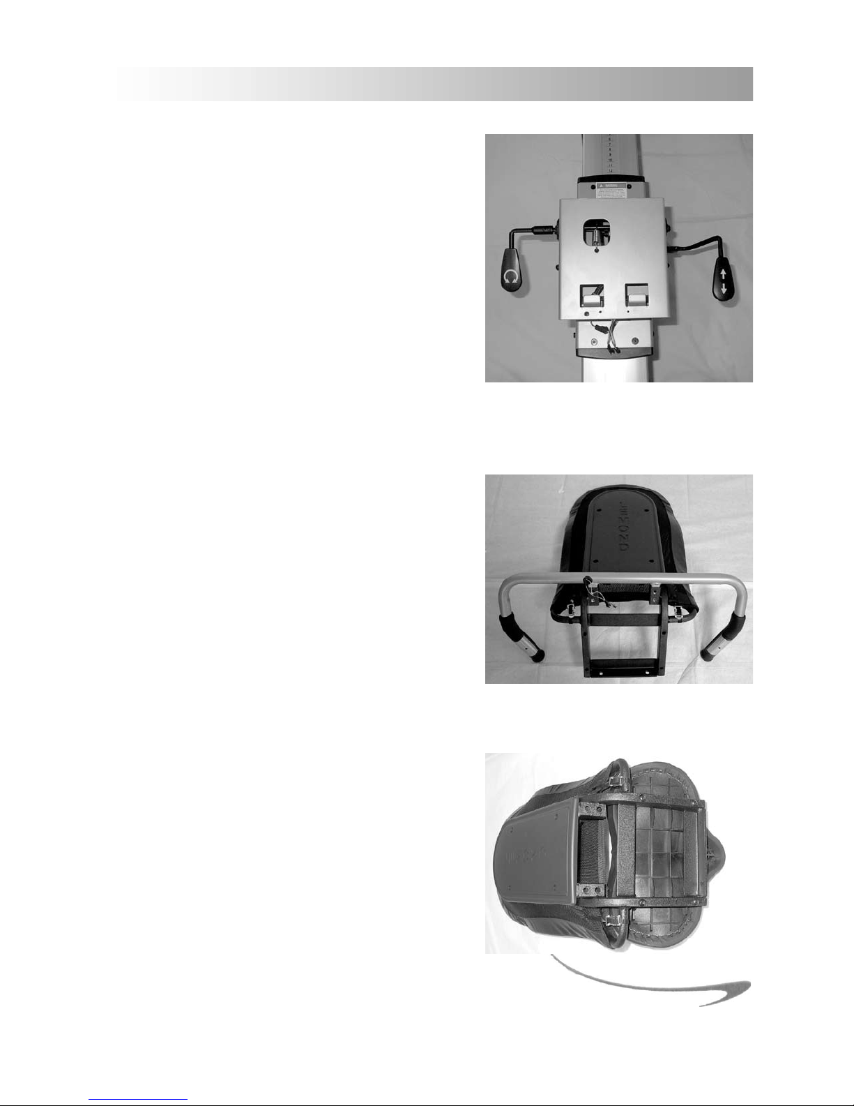
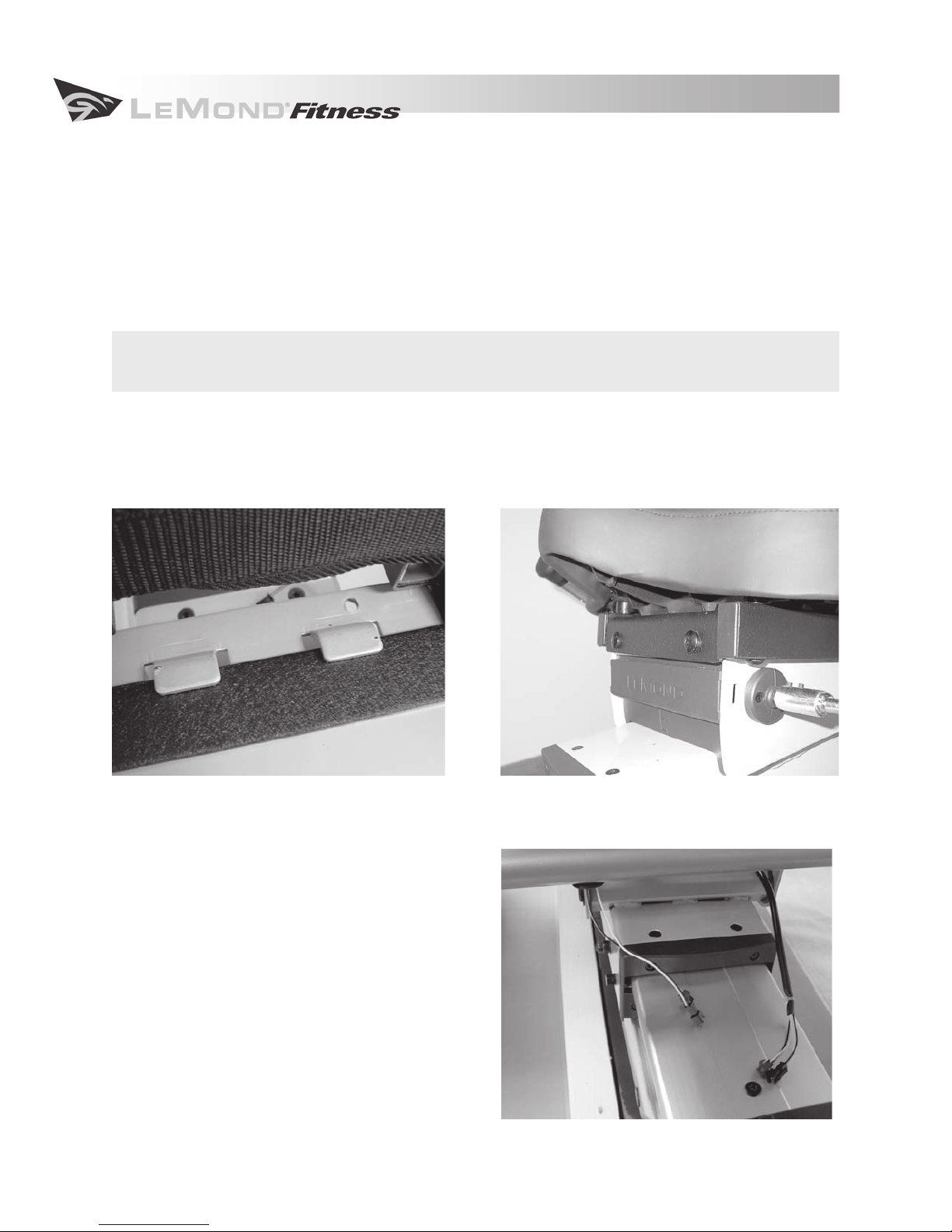
LeMond Fitness G-Force RT Installation guide

ASSEMBLY INSTRUCTIONS

2
3.1 Location
It is to your benet to choose a suitable location in your home for your new recumbent bike. The
g•force RT was designed to be an unobtrusive and attractive addition to your home. A smaller prole
and much quieter drive mechanism than other recumbent bikes, allows the bike to be situated and used
in almost any location in the home with a minimum of disruption. Make sure that the chosen location
provides adequate room for the equipment while it is in use. The physical dimensions of the assembled
bike are listed below.
Choose a setting that is comfortable and appealing and that will encourage you to continue with your
tness goals. A cool and dry location will make the time you spend exercising on the g•force RT more
enjoyable and will extend the life of the bike.
Dimensions for the assembled g•force RT Recumbent Fitness Bike
Physical Dimensions
Length 59.8 in (151.9 cm)
Width 28.6 in (72.6 cm)
Height 47.6 in (120.9 cm)
Weight 156 lbs (70.9 kg)

3
ASSEMBLY AND INSTALLATION INSTRUCTIONS
3.2 Getting Started
Follow these detailed instructions to quickly assemble your new bike and you will be on the way to start-
ing your new tness program.
Failure to follow these simple instructions will void your warranty
and could result in injury!
Your g•force RT will arrive in a single carton. Unpack the shipping carton in the location where the bike
will be assembled and used. Cut the shipping straps and remove the staples from the bottom edge and
then remove the top of the carton. The shipping carton contains two separate boxes and the body of the
bike.
Remove the cardboard box and the packaging materials from around the body of the bike. Unpack the
box and inspect each part thoroughly for any damage that may have occurred during shipping. Contact
the delivery carrier immediately if any damage is discovered. Contact the LeMond Fitness Customer
Service Department at (+1) 425.482.6773 between 7:00 a.m. – 5:00 p.m., M-F, Pacic time to report any
damages that have occurred during shipping.

4
3.3 Parts
Contents of Large Cardboard Box
Part Description Quantity
Plastic bag with tools, hardware and instructions 1
Front stabilizer with one wheel attached 1
Front wheel 1
Front wheel cap 1
Rear stabilizer with one foot attached 1
Rear leveling foot 1
Seat frame 1
Seat bottom 1
Handlebar 1
Console mast 1
Pedals 2
Cup holders 2
Contents of Small Cardboard Box
Part Description Quantity
Display Console 1
3.4 Tools and Hardware
All of the tools and hardware required for the assembly of your g•force RT are included in a plastic bag
in the large box inside the main shipping carton.

5
ASSEMBLY AND INSTALLATION INSTRUCTIONS
Tools and Hardware List
Part Number Description Quantity
SA10525 M5x25 screw 2
SC10830 M8x30 screw 4
SC10615 M6x15 screw 4
SC10515 M5x15 screw 4
SC10820 M8x20 screw 9
SC10850 M8x50 screw 4
SL20515 self-tapping screw 2
W108016 at washer 2
W308008 star washer 17
70390 fore/aft seat adjustment handle 1
70392 seat angle adjustment handle 1
70670 2.5 mm hex wrench 1
70669 3mm hex wrench 1
70668 4mm hex wrench 1
70667 6mm hex wrench 1
70671 pedal wrench 1
3.5 Assembling the Bike
The unique serial number of your g•force RT is located on the front tubing and near the bottom of the
bike. Please take a moment to nd and record the serial number of your bike.
Record your serial number in the box below as well as in the PRODUCT SERVICE section. Having easy ac-
cess to your serial number will help us provide you with great service more quickly should you need it.
ENTER YOUR SERIAL NUMBER IN THE BOX BELOW
M8x50 M6x15 at washer
M8x30 M5x25 star washer
M8x20 M5x15 self-tapping screw

6
3.5.1 Body
1. Fold down the sides of the carton base and
remove the packing material from around the
bike.
2. Leave the body of the bike on the carton base
while the remaining assembly is completed.
CAUTION: Remove the staples completely to
avoid injury.
3.5.2 Front Stabilizer
1. Locate the front stabilizer and the unattached wheel. The front stabilizer already has one wheel
attached.
2. Slide the front stabilizer into place at the front of the body frame from the left side. Rotate the
stabilizer until the set screw is positioned into the alignment notch. This will align the attach-
ment screw holes of the body and the front stabilizer. Be careful not to dislocate the plastic
sleeve at the opposite side of the tubing. If the sleeve is pushed out of place, remove the stabi-
lizer, replace the sleeve and reinstall the stabilizer.
3. Secure the front stabilizer by sliding star washers onto each of (2) M8x30 screws and tightening
with the 6mm hex wrench.
4. Slide the remaining front wheel onto the end of the front stabilizer and attach the wheel cap.
Use the alignment pins as a guide to install the wheel cap correctly.
5. Secure the wheel cap to the wheel with (2) self-tapping screws and tighten with the 3mm
wrench.

7
ASSEMBLY AND INSTALLATION INSTRUCTIONS
3.5.3 Rear Stabilizer
1. Locate the rear stabilizer and the
leveling feet.
2. Slide the rear stabilizer into place at the
rear of the body frame from the right
side and rotate until the set screw is
positioned in the alignment notch. As
with the front stabilizer, be careful not to
dislocate the plastic sleeve.
3. Align the holes for the attachment
screws on the body and the rear stabi-
lizer. Secure the rear stabilizer by sliding
star washers onto each of (2) M8x30 screws and tighten with the 6mm hex wrench.
4. Attach the leveling foot to the rear stabilizer by screwing it into the underside of the rear
stabilizer. Assume at rst, that your oors are level and install each foot snugly against the rear
stabilizer.
3.5.4 Display Console
Attaching the Console Mast to the Bike
1. Before installing the console mast to the body,
locate the (2) wires at the top of the front tube
on the body. Feed the wires through the tub-
ing and out of the hole at the top of the console
mast.
2. Insert the console mast into the front tubing of
the body, taking care to align the holes for the at-
tachment screws of the mast with both the body
and the plastic sleeve.
3. Secure the console mast to the body by sliding
star washers onto each of (3) M8x20 screws and
tighten with the 6mm hex wrench.

8
Attaching the Display Console to the Console Mast
Battery Installation
CAUTION: Never use conventional alkaline batteries. You will damage your electronic parts
and void your warranty.
The display console of the g•force RT is powered by (4) rechargeable AA nickel-metal hydride (Ni-MH)
batteries, which are included. You provide the power to recharge the batteries by simply pedaling and
working out on your bike.
1. Remove the battery compartment cover on the back of the display by pressing down on the tab
and then lifting the cover o. An illustration at the bottom of the battery compartment indicates
the correct positioning of the batteries.
2. Place the batteries into the compartment as indicated on the illustration. Insert the negative
end into position rst and then gently push
the positive end into place.
3. Replace the battery compartment cover.
Note:
Your batteries will not be fully charged when
your bike arrives. You will need to pedal for at least 1
hour to fully charge the batteries.
Attaching the Display Console
1. Connect the wires from the console mast to
the wires on the back of the display console.
2. Once connected, gently feed the wiring into
the console mast until the display console
can rest snugly against the platform. The
platform of the console mast should t
completely inside the grooved section of
the back of the display console.
3. Attach the display console to the console
mast using (4) M5x15 screws and tighten
with the 3mm hex wrench.

9
ASSEMBLY AND INSTALLATION INSTRUCTIONS
3.5.5 Seat
Attaching the Adjustment Handles to the Seat Carrier
1. Locate the seat adjustment handles. They can be
found in the plastic bag containing the tools and
other hardware.
2. The shorter, L-shaped handle is attached to the left
side of the bike and controls the seat angle adjust-
ment. Slide the handle onto the post on the left
side of the seat carrier so that the set screws make
contact with the at portion of the post. Tighten
the (2) set screws at the top of the handle with the
2.5 mm hex wrench.
3. The longer handle controls the fore/aft adjustment of the seat and is located on the right side of
the bike. Align the (2) holes of the handle with the (2) holes on the right side of the seat carrier.
Attach the handle with (2) M5x25 screws and tighten using the 3mm hex wrench.
Attaching the Handlebars to the Seat Assembly
Attach the handlebars to the seat assembly before attach-
ing the seat to the body of the bike.
1. Turn the seat assembly upside down so that the
seat rails and the seat back touch the oor.
2. Insert the handlebars into the seat assembly with
the holes on the handlebars facing up and aligned
with the holes on the seat carrier.
3. Secure the handlebars to the seat assembly by sliding (4) star washers onto each of the (4)
M8x20 screws and tighten using the 6mm hex wrench.
Attaching the Saddle to the Seat Assembly
1. Place the seat bottom on the rails of the seat
assembly.
2. Attach the seat bottom to the seat assembly by
sliding (4) star washers onto each of (4) M8x50
screws and tighten using the 6mm hex wrench.

10
Attaching the Seat Assembly to the Body
Note:
Install the handlebars and seat bottom before attaching the seat assembly to the body of the bike.
1. Locate the two tabs that are on the top surface of the seat carrier which is located on the seat
track of the body.
2. Located under the seat is a bar that runs the width of the seat. Hook the tabs of the seat carrier
over the bar on the seat assembly. (A)
CAUTION: Be careful not to pinch the wiring for the contact heart rate grips when attaching
the seat assembly to the seat carrier.
3. Lower the seat assembly over the seat carrier and align the holes at the front of the seat assem-
bly with those on the seat carrier. (B)
4. Secure the seat assembly to the seat carrier by sliding (2) at washers and (2) star washers onto
each of (2) M8x20 screws and tighten with the 6mm hex wrench.
Connecting the Wiring for the Contact
Heart Rate Grips
Once the seat assembly has been attached to the seat
carrier, connect the two wires on the handlebars to
their corresponding wires on the seat carrier.
The connection on each of the two wires is dierent.
There is only one correct way to make the connection.
Do not try to force the connection.
AB

11
ASSEMBLY AND INSTALLATION INSTRUCTIONS
3.5.6 Pedals
Note:
All bicycle pedals have a designated left and right. Your pedals are marked as such on the pedal itself.
Left and right orientation on the bike is determined as the position you would be in while riding the
bike. It is important that you attach each pedal to the corresponding crank, as the threads on the left
pedal and crank are reversed. Left pedals are always reverse-threaded so that the pedal tightens rather
than loosens while you are pedaling the bike.
CAUTION: Attempting to install the pedals on the incorrect side will cause damage to both
the pedal and the crank.
Attaching the Pedals to the Crank Arms
1. Before attaching the pedals to the cranks apply
multipurpose grease to the threads of each pedal.
Pedals that are not suciently lubricated will often
make a squeaking or clicking noise with every pedal
rotation which can become an annoyance.
2. Attach the left pedal (marked L) to the left crank.
Tighten with the pedal wrench in a COUNTER-
CLOCKWISE direction.
3. Attach the right pedal (marked R) to the right crank.
Tighten with the pedal wrench in a CLOCKWISE direction.
The cranks of the g•force RT have 9/16-20 threads, making the bike compatible with all standard pedal
systems, including the LeMond® Dual-sided Indoor Cycling Pedal.
3.5.7 Cup Holders
1. Place one cup holder in each bend of the handlebars. The cup holders are marked as left (L) or
right (R) on the underside of the holder.
2. Attach the cup holders with (4) M6x15 screws and tighten with the 4mm hex wrench.
3.6 Leveling the g•force RT
Now that the bike is fully assembled, carefully lift the rear end, and roll the bike to its nal location.
Check the stability of the bike by attempting to rock it from side to side. If the bike rocks or wobbles, it
should be leveled. A bike that is leveled correctly will provide a more stable and comfortable ride.
The two feet of the rear stabilizer can be adjusted to compensate for uneven oors. To level the bike,
simply raise or lower the two leveling feet by screwing them in or out as needed.

LeMond Fitness Inc.
17280 Woodinville-Redmond Road
Building B Suite 888
Woodinville, WA 98072 USA
www.Lemondtness.com
Telephone: (+1) 425.482.6773
Fax: (+1) 425.482.6724
Document #300205, Rev B
Table of contents
Other LeMond Fitness Exercise Bike manuals

LeMond Fitness
LeMond Fitness RevMaster User manual

LeMond Fitness
LeMond Fitness g-force UT User manual

LeMond Fitness
LeMond Fitness g-force UT User manual

LeMond Fitness
LeMond Fitness RevMaster User manual

LeMond Fitness
LeMond Fitness g-force UT User manual

LeMond Fitness
LeMond Fitness RevMaster 15100 User manual

LeMond Fitness
LeMond Fitness Revolution User manual