LeMond REvMaster User manual

Owner's Manual

Page iii
LeMond Fitness Inc.
17820 Woodinville-Redmond Rd.
Building B, Suite 888
Tel.: (425) 482-6773
Fax: (425) 482-6724
Visit our website at
www.LeMondfitness.com
P/N 300202
© 2002 LeMond Fitness Inc. LeMond and RevMaster
are registered trademarks.

Page iv
WARRANTY
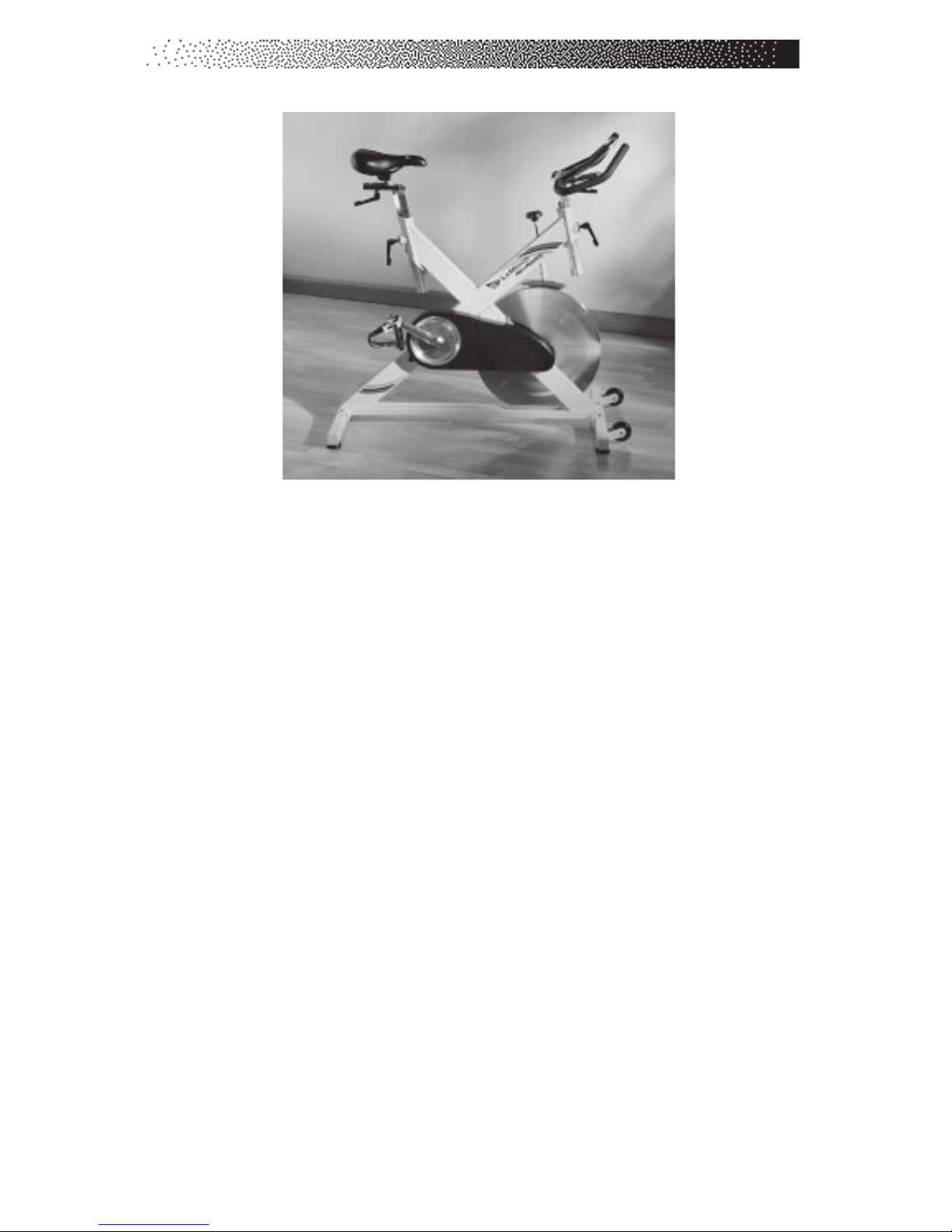
This is to certify that the LeMond®RevMaster™exercise bike is warranted by
LeMond Fitness Inc. to be free of all defects in materials and workmanship. This
warranty does not apply to any defect caused by negligence, misuse, accident,
alteration, improper maintenance, or an “act of God.”
The LeMond RevMaster carries a five-year frame warranty, a one-year
warranty on bottom bracket bearings, pillow block bearings, tension knob
assembly, a three-year warranty on cranks, bottom bracket spindle, flywheel,
handlebar, seat post, handlebar post, and a 90 day warranty on wearables such
as seat, grip, handles, and brake pad. Contact our Customer Service Department
to report any problems. When calling, please be prepared to provide the
customer service representative with the following information:
• Your name, customer number, shipping address, and telephone
number
• The serial number of the inoperable bike
• The date(s) of purchase for the inoperable bike(s)
• Your billing address
This information will ensure that you are the only one ordering parts
under your warranty protection. If warranty replacement parts are shipped to
you, you may be required to return the inoperable part. To facilitate this process,
the following policy has been established:
• Please call our Customer Service Department to receive a return
goods authorization prior to shipment.
• LeMond Fitness will incur all ground freight charges for warranty
parts ordered for a machine that is less than 45 days old.
• You are responsible for freight charges on warranty parts for
machines that are more than 45 days old. You will not be
responsible for the return shipment of the inoperable parts.
• Some inoperable warranty parts must be promptly returned to our
Customer Service Department. We will pay the shipping cost for the
inoperable warranty parts. Detailed instructions are included with
each warranty replacement part.
LeMond Fitness Inc. neither makes, assumes nor authorizes any
representative or other person to make or assume for us, any other warranty
whatsoever, whether expressed or implied, in connection with the sale, service, or
shipment of our products. We reserve the right to make changes and improve-
ments in our products without incurring any obligation to similarly alter products
previously purchased. In order to maintain your product warranty and to ensure
the safe and efficient operation of your machine, only authorized replacement
parts can be used. This warranty is void if parts other than those provided by
LeMond Fitness are used.

Page v
PREFACE
The LeMond®RevMaster™bike is a safe, functional, and effective
exercise modality for developing aerobic fitness and increasing the
strength of the major muscle groups of the lower body. It is designed for
use by individuals of all ages and fitness levels. Your purchase of this bike
is a positive affirmation of your commitment to use the best available
methods for enhancing your functional fitness capabilities. In order to
derive optimal benefits from your equipment, you should read this manual
thoroughly and adhere closely to the instructions.
WHAT IS IN THIS MANUAL?
Following the information on safety guidelines and an explanation of
installation procedures, this manual will provide general exercise guide-
lines and explain how the LeMond RevMaster exercise bike works.
Detailed instructions of parts removal and replacement are then followed
by exploded diagrams of the bike components.
WHAT IS THE LEMOND REVMASTER BIKE?
The LeMond RevMaster is a revolutionary new group exercise stationary
cycle from LeMond Fitness Inc. that delivers an extraordinary workout.
It has been designed to be stronger, more stable, feel more comfortable,
be easier to adjust, and have a more durable crank system then conven-
tional group exercise bikes.
The LeMond RevMaster bike was designed by Paul Swift under the
direction of Greg LeMond. LeMond is the first American to win the Tour
de France. A cyclist who has won the world's most challenging races,
Greg LeMond has also revolutionized the sport by introducing cutting
edge technology that is commonplace today. Paul Swift is a 15-year
member of the USA cycling team, eight-time national champion and 1998
Goodwill Games Gold Medalist.

Page vi
CONTENTS
SAFETY GUIDELINES .......................................................... 1
INSTALLATION INSTRUCTIONS..................................... 3
Delivery ........................................................................... 3
GUIDELINES FOR SAFE OPERATION ........................... 7
BASIC OPERATING INSTRUCTIONS ............................. 8
Your first workout on the LeMond® RevMaster®
Exercise Bike ................................................................. 8
Seat Adjustment ............................................................. 8
Handlebar Adjustment ................................................... 8
Pedal Strap Adjustment ................................................. 9
GENERAL EXERCISE GUIDELINES ................................ 10
Setting a goal ................................................................. 10
Flexibility Training .......................................................... 10
Exercise Principles ........................................................ 11
MAINTENANCE INSTRUCTIONS .................................... 12
Helpful Hints .................................................................. 12
Tool List ......................................................................... 12
Preventive Maintenance ................................................ 12
Daily ........................................................................ 13
Weekly .................................................................... 13
Monthly ................................................................... 13
TROUBLESHOOTING ......................................................... 14
Symptom: Adjustment Handles do not engage .............. 14
Symptom: Handlebar/Seat post will not slide up or down
................................................................................ 14
Symptom: Pedals are slipping ........................................ 14
Symptom: Pedals do not rotate ...................................... 14
PARTS REMOVAL AND REPLACEMENT ...................... 15
Adjustment Handles....................................................... 15
Belt ................................................................................ 16
Bottom Bracket Bearings .............................................. 16
Brake Pad Assembly ..................................................... 18

Page vii
CONTENTS
Covers ............................................................................ 19
Flywheel/Pillow Block Bearings .................................... 19
Handlebar ...................................................................... 20
Handlebar Post .............................................................. 20
Pedals ............................................................................ 21
Pedal Crank Arms ......................................................... 21
Seat ................................................................................ 22
Seat Slider ...................................................................... 22
Seat Post ........................................................................ 23
Tension Knob Assembly ................................................ 23
FIGURES ................................................................................ 24
Figure 1: Final Assembly ................................................ 24
Figure 2: Crank Assembly .............................................. 25
Figure 3: Flywheel Assembly ......................................... 26
Figure 4: Belt Tension .................................................... 27
Figure 5: Front Base Assembly ...................................... 28
Figure 6: Rear base Assembly ....................................... 29
Figure 7: Brake Tension Knob Assembly ...................... 30
Figure 8: Brake Pad Assembly ...................................... 31
Figure 9: V-Plunger & Plug ........................................... 32
SPECIFICATIONS ................................................................. 33
LIST OF TABLES
Table 1. Dimensions and Specifications for the
LeMond® RevMaster®Exercise Bike............................ 3

Page 1
IMPORTANT SAFETY INSTRUCTIONS
This symbol appearing throughout this manual means
Attention! Be Alert! Your safety is involved.
The following definition applies to the word “WARNING” found
throughout this manual:
WARNING - Used to call attention to POTENTIAL hazards that
could result in personal injury or loss of life.
READ ALL INSTRUCTIONS BEFORE USING THIS EXERCISE EQUIPMENT.
1. Close supervision is necessary whenever the equipment is used by, or
near children, invalids, or disabled persons. A serious injury could result
from a child's fascination with the moving components of the exercise
system.
2. Keep your hands away from all moving parts and keep your feet on the
pedals while exercising. Do not remove your feet from the RevMaster®bike
pedals while they are in motion.
3. Use this equipment only for its intended use as described in this Manual. Do
not attempt to ride this bike at high pedal speeds or in a standing position
until you practiced and are comfortable riding at slower pedal speeds.
4. Rotate the tension knob clockwise to apply resistance to the flywheel prior
to standing on the pedals.
5. Do not dismount the RevMaster bike until both of the pedals and the
flywheel are at a complete stop.
6. Never turn the pedal crank arms by hand. Do not expose your hands or your
arms to the drive mechanism as possible injury could occur.
SAFETY GUIDELINES
!

Page 2
7. Do not perform push-up type movements on the handlebars.
8. After exercising, turn the tension knob clockwise or push down on the
tension knob to slow the flywheel down so that the pedals do not rotate
freely and possibly hurt somebody.
9. Never drop or insert any object into any opening on the exercise equipment.
The safety level given by the design of this equipment can only be maintained
when the equipment is regularly examined for damage and wear. Inoperable
components should be replaced immediately or the equipment should be put out
of use until it is repaired.
Failure to follow all guidelines may compromise the effectiveness of the
exercise experience, expose yourself (and possibly others) to injury, and reduce
the longevity of the equipment.
SAVE THESE INSTRUCTIONS
Your comments and suggestions are welcome. Congratulations, and thank
you for buying the RevMaster!
Your serial
number(s):___________________________________________
___________________________________________________________
___________________________________________________________
___________________________________________________________
___________________________________________________________
___________________________________________________________
___________________________________________________________
____________________________________________________________
___________________________________________________________
Your LeMond Fitness
Dealer:______________________________________
Phone:______________________________________________________
SAFETY GUIDELINES

Page 3
Before leaving the manufacturing facility, your LeMond®RevMaster®
exercise bike was thoroughly inspected and tested for proper operation.
To minimize shipping damage, careful attention was given to making your
bike ready for shipment. The dimensions of the machine are listed in
Table 1.
Table 1. Dimensions for the LeMond®RevMaster™Bike
Physical Dimensions:
Length 41.50 inches (105 cm)
Width 22.25 inches (57 cm)
Height 38.00 inches (97 cm)
Weight 116 pounds (53 kg)
DELIVERY
Your LeMond RevMaster will arrive packed in 1 carton. Upon arrival
fully inspect the carton for damage. Point out any damage to the delivery
person and have the delivery person record the damage on the delivery
paperwork. Contact the Customer Service Department at (425) 482-6773
to report any damage.
Please follow these detailed instructions and you will find that your
bike can be unpacked and assembled with ease.
A. Remove the bike and components from the shipping carton
1. Move the box to the desired location. Ensure that the carton is
standing upright and remove the strapping material.
2. Pull the cardboard edge out along the bottom of the box to
remove the staples. Lift the top of the box up and set aside.
3. Remove the two smaller boxes from the main frame of the bike.
4. Open both boxes and verify that you have all of the hardware
and parts necessary to assemble your bike. You should have an
owner's manual and the following parts:
INSTALLATION INSTRUCTIONS

Page 4
INSTALLATION INSTRUCTIONS
B. Assemble the Bike
5. With the help of an assistant, lift the bike up and off the pallet.
6. The base that has wheels is the
front base and connects to the
main frame below the flywheel.
Ensure that the wheels are
facing out, and align the 2 holes
in the front base with the 2
holes in the frame. Insert a
mounting bolt into the top of the
hole and push the bolt through the base and the main
frame. Use the 8-mm hex key and wrench tool to secure the
mounting bolt nut. Repeat this procedure for the rear base.
Note: If you are having difficulty threading the nut on the
bolt, prop up the main frame using the inclosed wooden
blocks to allow accessibility to the nut.
Handlebar Post
4x Mounting Bolts
3x Hex Keys
Wrench Tool
Seat
Pedals
Water Bottle Cage
4x Handles Seat Post
Handlebar Assembly
Front Base
Rear Base

Page 5
7. The handlebar post is the post that has a smooth finish, and no
groove on top. Insert the handlebar post into the handlebar tube.
Loosely thread a handle without a washer into the main frame.
Raise the handlebar post to the desired height and tighten the
handle to secure the handlebar post.
Note: The black handles are spring loaded. Once tightened,
ensure that the handle does not stick out to the side from the
main frame. Pull down on the handle and rotate it such that it
does not stick out. Release the handle and lock it into place.
8. Position the handlebar over the handlebar post. Loosely thread a
handle with a washer through the handlebar post into the handle-
bar. Slide the handlebar to the desired
position and tighten the handle.
9. The 4-mm screw that mounts the
water bottle cage is located in the
water bottle clamp on the handlebar
assembly. Remove the screw from
the clamp and position the water
bottle cage over the clamp. Reinstall the screw and tighten the
water bottle cage to the clamp.
10. The seat post is the post that has a rough finish, and a groove on
top. Insert the seat post into the seat post tube. Loosely thread a
handle without a washer into the main frame. Raise the seat post
to the desired height and tighten the handle to secure the seat
post.
INSTALLATION INSTRUCTIONS
Handlebar Post
Seat Post

Page 6
11. Position the seat with seat slider over
the seat post. Loosely thread a
handle with a washer through the seat
post into the seat slider. Slide the seat
to the desired position and tighten the
handle.
12. The pedals are marked as if you are seated on the bike, "R" for
right, and "L" for left. Carefully thread the right pedal into the
crank arm with your fingers - do not cross thread the pedal in the
crank arm! Use the wrench tool to tighten the pedal. Repeat this
step for the left pedal.
Note: The left pedal is reverse-threaded.
Seat Post
Seat Post
Adjustment
Handle
Seat
Seat Adjustment
Handle
Handlebar
Handlebar Post
Adjustment Handle
Front Cross Arm
Back Cross Arm
INSTALLATION INSTRUCTIONS

Page 7
!WARNING
THESE GUIDELINESARE DIRECTED TO YOU, AS THE OWNER OF
THIS EXERCISE EQUIPMENT. YOU SHOULD INSISTTHATALL
USERS FOLLOW THE SAME GUIDELINES. YOU SHOULD MAKE
THIS MANUALAVAILABLE TOALL USERS.
1. Obtain a complete physical examination from your medical doctor and
enlist a health/fitness professional’s aid in developing an exercise
program suitable for your current health status.
2. When working out for the first time, start out slowly for a minimum of
five minutes. After your muscles are warmed up, gradually increase
the pedaling rate and/or resistance to a speed that allows you to attain
your target heart rate zone.
3. The speed and duration of your exercise program should always be
subject to how you feel. Never permit peer pressure to exceed your
personal judgment while exercising.
4. Overweight or severely deconditioned individuals should be particu-
larly cautious when using the equipment for the first time. Even
though such individuals may not have histories of serious physical
problems, they may perceive the exercise to be far less intense than it
really is, resulting in the possibility of overexertion or injury.
5. Although all equipment manufactured by LeMond®Fitness, Inc. has
been thoroughly inspected by the manufacturing facility prior to
shipment, proper installation and regular maintenance are required to
ensure safety. Maintenance is the sole responsibility of the owner.
GUIDELINES FOR SAFE OPERATION

Page 8
YOUR FIRST WORKOUT ON THE LEMOND®REVMASTER™
EXERCISE SYSTEM
Basic Instructions for First-Time Users
1. Properly fit the bike to your body type. The RevMaster offers up/
down and fore/aft adjustments that are clearly marked to ensure a
quick and easy custom fit for each workout.
Seat adjustment:
1. Rotate the pedals so that one of the pedals is in the upward
position.
2. Place your foot in the toe clip of the pedal
closest to the floor and mount the bike. Ensure
that the ball of your foot is over the center of
the pedal. Your leg should be slightly bent at the
knee as shown in the picture to the right.
3. If your leg is too straight or your foot cannot
touch the pedal you will need to lower the seat.
If your leg is bent too much you will need to raise the seat.
4. Dismount the bike and rotate the seat post adjustment handle
counterclockwise. Once loosened you may slide the seat post up
or down as necessary.
5. When the seat is in the desired position rotate the seat stem
adjustment handle clockwise to secure the seat post. Note the
final position mark on the seat stem for future reference.
6. Adjusting the seat fore or aft allows for better fit. Rotate the seat
adjustment handle counter clockwise and slide the seat forward
or backward as desired. Rotate the seat adjustment handle
clockwise to secure the seat. Note the final position mark under
the seat for future reference.
Handlebar adjustment:
1. Raise or lower the handlebars by rotating the handlebar post
adjustment handle counterclockwise and sliding the handlebar
post up or down as desired. Rotate the handlebar adjustment
handle clockwise to secure the handlebar post. Note the final
BASIC OPERATING INSTRUCTIONS

Page 9
!
position mark on the handlebar stem for future reference.
2. Adjust the handlebar fore or aft by rotating the handlebar adjust-
ment handle counter clockwise and sliding the handlebar forward
or backward as desired. Note the final position mark on the
handlebar for future reference.
Pedal strap adjustment:
1. Place the ball of each foot on the pedal and in the toe clip such
that the ball of the foot is centered over the pedal spindle (center
of the pedal).
2. Rotate one foot to within arm's reach and pull up on the toe clip
strap. Repeat for the other foot.
3. Keep your knees positioned over your foot as you pedal.
2. Once you are in position and sitting comfortably on the bike, slowly
begin pedaling. Allow your hands to rest comfortably on the handle-
bar. If you have not warmed up prior to mounting the bike, pedal
slowly for at least five minutes before beginning your exercise
program.
WARNING
IFAT ANY TIME DURING YOUR WORKOUT YOU FEEL CHEST PAIN, EXPERIENCE SEVERE
MUSCULAR DISCOMFORT, FEEL FAINT, OR ARE SHORT OF BREATH, STOP EXERCISING
IMMEDIATELY. IFTHE CONDITION PERSISTS, YOU SHOULD CONSULT YOUR MEDICAL
DOCTOR IMMEDIATELY.
3. Pedaling resistance is controlled by the tension knob located beneath
the handlebar on the main "X" part of the frame. Resistance may be
changed at any time by turning the tension knob clockwise (more
resistance) or counterclockwise (less resistance).
4. Before dismounting, push down on the tension knob or rotate the
tension knob clockwise to brake the flywheel so that the pedals do not
turn freely.
5. Dismount the bike by first loosening each toe clip strap and then
removing your feet from the pedals. Step off the bike.
BASIC OPERATING INSTRUCTIONS

Page 10
SETTING A GOAL
The first step to a successful exercise program is to set realistic goals and
objectives. Are you wanting an exercise program that is geared to build
muscle, maintain muscle tone, or lose weight? In order to ensure that you
fully receive all the benefits of a sound exercise program, you need to
first identify the existence (if any) of risk factors that may influence the
design of your exercise program. Based upon a comprehensive analysis
of your personal exercise needs and interests, you should then develop (or
have developed for you by a competent or trained professional) an
individualized program of exercise that is enjoyable, easy, and yet chal-
lenging. Your greatest health benefit will come from a lifestyle change
that encourages a lifetime of physical activity.
One way to guarantee success in reaching your goal is to eat cor-
rectly. A well-rounded diet provides the proteins, carbohydrates, fats,
vitamins, minerals, and water necessary for good health. If you are
unsure of your dietary needs, seek the advise of your physician, an
exercise professional, or visit your local bookstore for more information
on nutrition.
FLEXIBILITY TRAINING*
Achieving and maintaining an adequate range of motion should always be
objectives of a comprehensive exercise program. The warm-up phase of
your exercise session should include some type of light warm-up activity
to increase both your heart rate and your body temperature, which is then
followed by flexibility exercises that are specifically designed to stretch
the musculature around your body’s major skeletal joints. Attempting to
stretch a cold muscle can be dangerous to the soft tissues surrounding the
muscle. No matter how controlled the movement, forcing a muscle
through a full range of motion (and beyond) without appropriately warm-
ing up is both unsafe and counterproductive.
A general exercise program for achieving and maintaining flexibility
should adhere to the following guidelines:
•Frequency - daily
•Intensity - to a position of mild discomfort
GENERAL EXERCISE GUIDELINES

Page 11
•Duration - 10-30 seconds for each stretch
•Repetitions - 2-6 for each stretch
•Type - static, with a major emphasis on the low back
and hamstrings area because of the high preva-
lence of low-back pain syndrome in our society.
EXERCISE PRINCIPLES*
The American College of Sports Medicine has developed a position paper
concerning exercise programs for healthy adults and the need for guide-
lines. The following recommendations concern the quantity and quality of
(exercise) training for developing and maintaining cardiorespiratory
fitness in a healthy adult:
•Frequency -3 to 5 days per week
•Intensity -50% - 85% of maximum oxygen
uptake (VO2 max)
•Duration -20 to 60 minutes of continuous
aerobicactivity
•Mode of Activity -Any activity that uses the large
muscle groups, that can be
maintained continuously, and is
rhythmical and aerobic in nature.
•Rate of Progression -Initial Conditioning - 4 to 6 weeks; low-
end intensity (40% - 60% VO2 max); low-
end duration (15 to 20 minutes).
-Improvement Stage - 6 weeks to 6
months; moderate intensity; moderate
duration.
-Maintenance Stage - 6 months plus;
moderate to high intensity; moderate to
high duration.
*Note: Some of the material contained in this section is adapted from The
StairMaster®Fitness Handbook 2nd Ed., James A Peterson, and
Cedric X. Bryant (editors), Sagamore Publishing, 1995.
GENERAL EXERCISE GUIDELINES

Page 12
MAINTENANCE INSTRUCTIONS
HELPFUL HINTS
The safety level given by the design of this equipment can only be
maintained when the equipment is regularly examined for damage and
wear. Inoperable components should be replaced immediately or the
equipment should be put out of use until it is repaired. Read all mainte-
nance instructions thoroughly before beginning work.
All references to the right or left side and to the front or back are
made as if you were on the exercise equipment ready to exercise. For
example, the belt is on the right side of the bike.
TOOL LIST
The following tools are needed to perform service and maintenance:
• Combination wrench (included)
• Metric allen wrenches (included)
• Phillips screwdriver
• Shimano®-compatible bottom bracket tool + 1/2" driver
• Lock ring removal tool
• Bicycle crank arm puller
INITIAL SERVICE
Upon receiving your equipment, use a soft clean cloth to wipe off the
dust that may have accumulated during shipping. Your equipment will
need minor assembly. Refer to the "Installation Instructions" section of
this manual for details.
PREVENTIVE MAINTENANCE
Refer to the appropriate "Parts Removal and Replacement" section of
this manual for all disassembly and assembly instructions. If you experi-
ence any problems, contact our Customer Service Department at (425)
482-6773.

Page 13
Daily
1. Wipe down the LeMond®RevMaster™after each use to remove
sweat and moisture. Use soap and water, or a diluted non-abrasive
cleaner solution. Rinse to remove detergent residue and then dry.
2. If your bikes are used frequently in group exercise sessions, inspect
for loose pedals prior to starting any class. Tighten any loose pedals.
Weekly
1. Inspect the brake pad for excessive wear or dryness. If necessary,
lubricate the leather brake pad with 3-N-ONE® oil. If the sponge
padding is showing through the brake pad, replace the brake pad.
2. Wipe down the flywheel with WD-40®. This product will clean the
surface of the flywheel and provide a protective barrier against
moisture.
Monthly
1. Inspect the belt for correct alignment and tension. A properly
tensioned belt will not slip when pedaling the bike standing up. Check
the belt for excessive wear. Replace any belt that is cracked, frayed,
or otherwise non-uniform.
2. Inspect the bottom bracket assembly for looseness. The left bearing
cup is adjustable, and over time may loosen. With a small rubber
mallet, tap on the crank bolt on both sides If you see side to side
movement you must remove the crank arm(s) and properly adjust the
bearing cup(s).
MAINTENANCE INSTRUCTIONS

Page 14
TROUBLESHOOTING
This section outlines tests to systematically identify and isolate the cause
of common problems. The first step is to identify the problem. Once you
have identified the problem, perform the tests in exactly the same order
as written. Refer to the appropriate "Parts Removal and Replacement"
section of this manual for all disassembly and assembly instructions. To
order a replacement part , or to get help with the troubleshooting process,
contact the Customer Service Department at (425) 482-6773.
SYMPTOM: Adjustment handles do not engage
1. If the adjustment handle fails to engage properly replace the adjust-
ment handle.
SYMPTOM: Handlebar/Seat post will not slide in the frame tube
1. Remove handlebar/seat post and look down inside of the frame tube.
TheV-Plunger may have fallen out of its proper location and could be
blocking the tube. If necessary, push the V-Plunger back into position
with your fingers. Reinstall the handlebar/seat post and adjustment
handle.
SYMPTOM: Pedals are slipping
1. Inspect the belt for proper tension. If necessary, tighten the belt.
SYMPTOM: Knocking noise or play felt in pedals/crank
1. Inspect the pedal crank arm bolts. If they have loosened, apply
Loctite®on the crank arm bolt threads and tighten.
2. If the symptom is still there, check the bottom bracket bearing cups
for looseness. Tighten if necessary.
3. If the symptom still persists, remove the bottom bracket bearings.
Replace the bottom bracket assembly if necessary.
SYMPTOM: Crank arms do not rotate
1. Remove the pedals crank arms and try to rotate the bottom bracket
shaft. Ensure that the bottom bracket bearing cups have not loosened
and backed into the crank arms. Adjust the bearing cups and use
Loctite to secure the bottom bracket bearing cups.
2. If the bottom bracket bearing cups are too tight, loosen the bearing
cups and try to rotate the bottom bracket shaft. If it does not rotate,
replace the bottom bracket bearings.
Other manuals for REvMaster
4
Table of contents
Other LeMond Exercise Bike manuals

LeMond
LeMond G-force rt User manual

LeMond
LeMond RevMaster Sport User manual

LeMond
LeMond REvMaster User manual

LeMond
LeMond RevMaster Sport User manual

LeMond
LeMond REvMaster User manual

LeMond
LeMond REvMaster User manual

LeMond
LeMond REvMaster User manual

LeMond
LeMond LeMond RevMaster Bikes LM350000-5 User manual

LeMond
LeMond Revolution 250202-2 User manual