Lennox HS29-072 User manual

504,561M
*P504561M*
Page 1
09/02
*2P0902*
HS29−072
HS29−120
HS29−090
Retain These Instructions
For Future Reference
IMPORTANT
Improper installation, adjustments, alteration, ser
vice or maintenance can cause property damage,
personal injury or loss of life. Installation and ser
vice must be performed by a qualified installer or
servcice agency.
INSTALLATION
INSTRUCTIONS
HS29−072 (6 TON)
HS29−090 (7.5 TON)
HS29−120 (10 TON)
All units are equipped with a scroll compressor
CONDENSING UNITS
504,561M
09/02
Supersedes 504,544M
See unit nameplate for manufacturer and address.
2002
Table of Contents
Shipping & Packing List 1. . . . . . . . . . . . . . . . . . . . . . . . .
General Information 1. . . . . . . . . . . . . . . . . . . . . . . . . . . .
Dimensions 2. . . . . . . . . . . . . . . . . . . . . . . . . . . . . . . . . . . .
Parts Arrangement 4. . . . . . . . . . . . . . . . . . . . . . . . . . . . .
Control Box Arrangement 5. . . . . . . . . . . . . . . . . . . . . . . .
Setting the Unit 6. . . . . . . . . . . . . . . . . . . . . . . . . . . . . . . .
Rigging the Unit for Lifting 7. . . . . . . . . . . . . . . . . . . . . . .
Electrical 7. . . . . . . . . . . . . . . . . . . . . . . . . . . . . . . . . . . . . .
Plumbing 10. . . . . . . . . . . . . . . . . . . . . . . . . . . . . . . . . . . . .
Service Valves 17. . . . . . . . . . . . . . . . . . . . . . . . . . . . . . . .
Leak Testing 18. . . . . . . . . . . . . . . . . . . . . . . . . . . . . . . . . .
Evacuation & Dehydration 18. . . . . . . . . . . . . . . . . . . . . .
Start−Up 19. . . . . . . . . . . . . . . . . . . . . . . . . . . . . . . . . . . . . .
Charging 20. . . . . . . . . . . . . . . . . . . . . . . . . . . . . . . . . . . . .
System Operation 21. . . . . . . . . . . . . . . . . . . . . . . . . . . . .
Maintenance 21. . . . . . . . . . . . . . . . . . . . . . . . . . . . . . . . . .
Start−Up & Performance Check List 22. . . . . . . . . . . . . .
Shipping & Packing List
1 − Assembled condensing unit
1 − Filter drier
Check equipment for shipping damage. If you find any
damage, immediately contact the last carrier.
General Information
These instructions are intended as a general guide and do
not supersede local codes in any way. Consult authorities
having jurisdiction before installation.
IMPORTANT
The Clean Air Act of 1990 bans the intentional vent
ing of refrigerant (CFCs and HCFCs) as of July 1,
1992. Approved methods of recovery, recycling or
reclaiming must be followed. Fines and/or incar
ceration may be levied for noncompliance.
IMPORTANT
Units are shipped with a holding charge of dry air
and helium, which must be removed before the unit
is evacuated and charged with refrigerant.
Litho U.S.A.

Page 2
HS29−072 & HS29−090 Dimensions − inches (mm)
Corner Weight
Model No
AA BB CC DD
Model No. lbs. kg lbs. kg lbs. kg lbs. kg
HS29−072 66 30 78 35 95 43 81 37
HS29−090 87 39 93 42 117 53 109 49
Center Of Gravity
Model No
EE FF
Model No. inch mm inch mm
HS29−072 22−3/4 578 16 406
HS29−090 23−7/8 606 15−3/4 400
Outdoor Coil
Top View
(HS29−072)
Service View
Outdoor Fan
And Guard
Outdoor Coil
Top View
(HS29−090)
Outdoor Fan
And Guard
CompressorCompressor
Inlet
Air
Inlet
Air
Inlet
Air
Inlet
Air
Inlet
Air
AA BB
CCDD
Center Of
Gravity
EE
FF
AA BB
CCDD
Center Of
Gravity
EE
FF
Compressor
A
31/4
(83)
34 (864)
B
Control
Box
Access
Side View
Lifting Holes
(For Rigging)
Forklift Slots
(Both Sides)
Electrical Inlets
(Either Side)
Liquid Line
(Either Side)
21/4 (57)
48 (1219)
11 11/16
(297)
Discharge Air
Control Box
C
151/2
(394)
Optional Hail Guard
(Field Installed All Coil Sides)
493/4 (1264) 353/4 (908)
Base Base
65/8
(168)
Suction Line
(Either Side)
31/2 (89)
Hot Gas
Bypass
(Either Side)
2
(51)
Optional Hail Guard
(Field Installed All Coil Sides)
Outdoor Coil
Outdoor Coil
Model No
A B C
Model No. in. mm in. mm in. mm
HS29−072 35 889 31−1/2 800 10 254
HS29−090 41−1/4 1048 37−3/4 959 10 254

Page 3
HS29−120 Dimensions − inches (mm)
Corner Weight
MdlN
AA BB CC DD
Model No. lbs. kg lbs. kg lbs. kg lbs. kg
HS29−120 118 54 161 73 161 73 118 54
Center Of Gravity
MdlN
EE FF
Model No. inch mm inch mm
HS29−120 30−1/2 775 17−5/8 448
Side View
Top View
70−3/4
(1797)
Outdoor Coil
Outdoor Coil
Outdoor Fans And
Guards (2)
Control
Box
Lifting Holes
(For Rigging)
Forklift SlotS
(Both Sides)
Discharge Air
Inlet Air
Electrical Inlets
(Either Side)
Liquid Line
(Either Side)
1−7/16
(37) 65/8
(168)
43/8
(111)
AA BB
CCDD
Center Of
Gravity
EE
FF
Control Box
34
(864)
49
(1245)
Compressor
Control
Box Access
31/4
(83)
Service View
72 (1829) 353/4 (908)
Base Base
Suction Line
(Either Side)
3−3/8
(86)
Optional Hail Guard
(Field Installed Both Sides)
Optional Hail Guard
(Field Installed Both Sides)
1−3/4
(44)
12
(305)

Page 4
HS29−072, 090 Unit Parts Arrangement
Figure 1
(HS29−072)
condenser fan
motor (B4)
high pressure
switch (S4)
control box
suction line
service valve
low pressure switch
(S87)
low ambient switch
(S11)
fan guard
compressor (B1)
liquid line
service valve
HS29−120 Unit Parts Arrangement
Figure 2
condenser fan
motor (B4, B5)
control box
low ambient switch (S11) on
liquid line
low pressure switch (S87)
high pressure switch
(S4)
fan guards
compressor (B1)
liquid line
service valve
suction line
service valve

Page 5
HS29−072 & HS29−090 Control Box Arrangement
Figure 3
contactor
(K1)
capacitor
(C1)
minimum
run timer
(DL33)
outdoor fan relay
(K10)
latching relay
(K167)
ground lug
HS29−120 Control Box Arrangement
Figure 4
contactor (K1) low ambient
thermostat
(S41)
capacitor
(C1,C2)
latching
relay (K167)
outdoor fan
relay 2 (K68)
outdoor fan
relay 1 (K10)
minimum run
timer (DL33)
ground
lug

Page 6
WARNING
NOTE − The matching indoor unit contains fiber
glass wool.
Disturbing the insulation in this product during
installation, maintenance, or repair will expose you
to fiberglass wool dust. Breathing this may cause
lung cancer. (Fiberglass wool is known to the State
of California to cause cancer.)
Fiberglass wool may also cause respiratory, skin,
and eye irritation.
To reduce exposure to this substance or for further
information, consult material safety data sheets
available from address shown below, or contact
your supervisor.
Setting the Unit
Refer to the unit dimensions for sizing requirements of the
mounting slab, platforms, or supports. Refer to figure 5 for
installation clearances.
Slab Mounting
When installing the unit at grade level, install it on a level
slab that is high enough above grade to allow water to drain
adequately. Locate the top of the slab so that run−off water
from higher ground will not collect around the unit.
Roof Mounting
Install the unit at a minimum of 4 inches (102 mm) above
the surface of the roof. Ensure that the weight of the unit is
properly distributed over roof joists and rafters. Use either
redwood or steel supports.
*One of these clearance distances may be reduced to 18 inches (457 mm).
**This clearance may be reduced to 12 inches (305 mm).
Note− 48 in. (1219 mm) clearance required above top of unit.
Installation Clearances
Figure 5
HS29−072, 090 (HS29−090 Shown)
HS29−120
Outdoor Coil
Outdoor Coil
36
(914)
36*
(914)
36*
(914)
36**
(914)
*36
(914)
36
(914)
*36
(914)
*36
(914)
Figure 6
Caution − do not walk on unit.
Important − all panels must be in
place for rigging.
Lifting point should be directly above the
center of gravity.
319
405
557
145
184
253
Unit *Weight
LBS. KG.
*Maximum weight with all available
factory−installed accessories.
HS29−072
HS29−090
HS29−120
Rigging Instructions

Page 7
Rigging the Unit for Lifting
Rig the unit for lifting by attaching four cables to the holes in
the base rail of the unit. See figure 6.
1 − Detach the protective wooden base before rigging the
unit for lifting.
2 − Connect the rigging to the holes in each corner of the
unit’s base.
3 − All panels must be in place for rigging.
4 − Place a fieldprovided Hstyle frame just above the
top edge of the unit. The frame must be of adequate
strength and length. (An Hstyle frame will prevent
the top of the unit from being damaged.)
CAUTION
As with any mechanical equipment, personal injury
can result from contact with sharp sheet metal
edges. Be careful when you handle this equipment.
Electrical
Wiring must conform to current standards of the National
Electric Code (NEC), Canadian Electrical Code (CEC),
and local codes. Refer to the furnace or blower coil installa
tion instructions for additional wiring application diagrams.
Refer to the unit nameplate for minimum circuit ampacity
and maximum overcurrent protection size.
WARNING
Unit must be grounded in accordance with
national and local codes.
Electric Shock Hazard.
Can cause injury or death.
Line Voltage
Knockouts are provided in the cabinet panel so that the wir
ing conduit can pass through the cabinet. Refer to figure 7
for field wiring diagram.
NOTE − Units are approved to be used only with copper
conductors.
24V, Class II Circuit
Make 24V, Class II Circuit connections below the control
box. Route the wire through the conduit to the bottom of
control box.
NOTE − A complete unit wiring diagram is located on the
inside of the unit access panel.
Figure 7
G1
G
Y1
W1
RY1 W2
G
LOW
VOLTAGE
TERMINAL
STRIP
B3
C
BLOWER
COMPARTMENT
MOTOR
SEE G24–200 INSTALLATION
INSTRUCTIONS FOR POWER SUPPLY
DRIVE KIT & TRANSFORMER
W1
G
W2
Y1
Y2
R
TB1
ECON
TB34
2
2
1
1
CONTROL BOX
CONNECTIONS IN CONTROL BOX.
24V–C
24V–R
1
NOTE − G and G1 wires MUST be routed from the
thermostat to the condensing unit as shown, to ensure
blower and compressor operation interlock.
Condensing Unit Field Wiring Diagram with Gas Furnace
(G24−200 Shown)
Thermostat
HS29
Condensing Unit
indoor Unit
(G24−200 SHOWN)
GREEN
GREEN
RED
YELLOW
GRAY

Page 8
Typical Unit Wiring Diagram
HS29−072, 090
Figure 8

Page 9
Typical Unit Wiring Diagram
HS29−120
Figure 9

Page 10
Plumbing
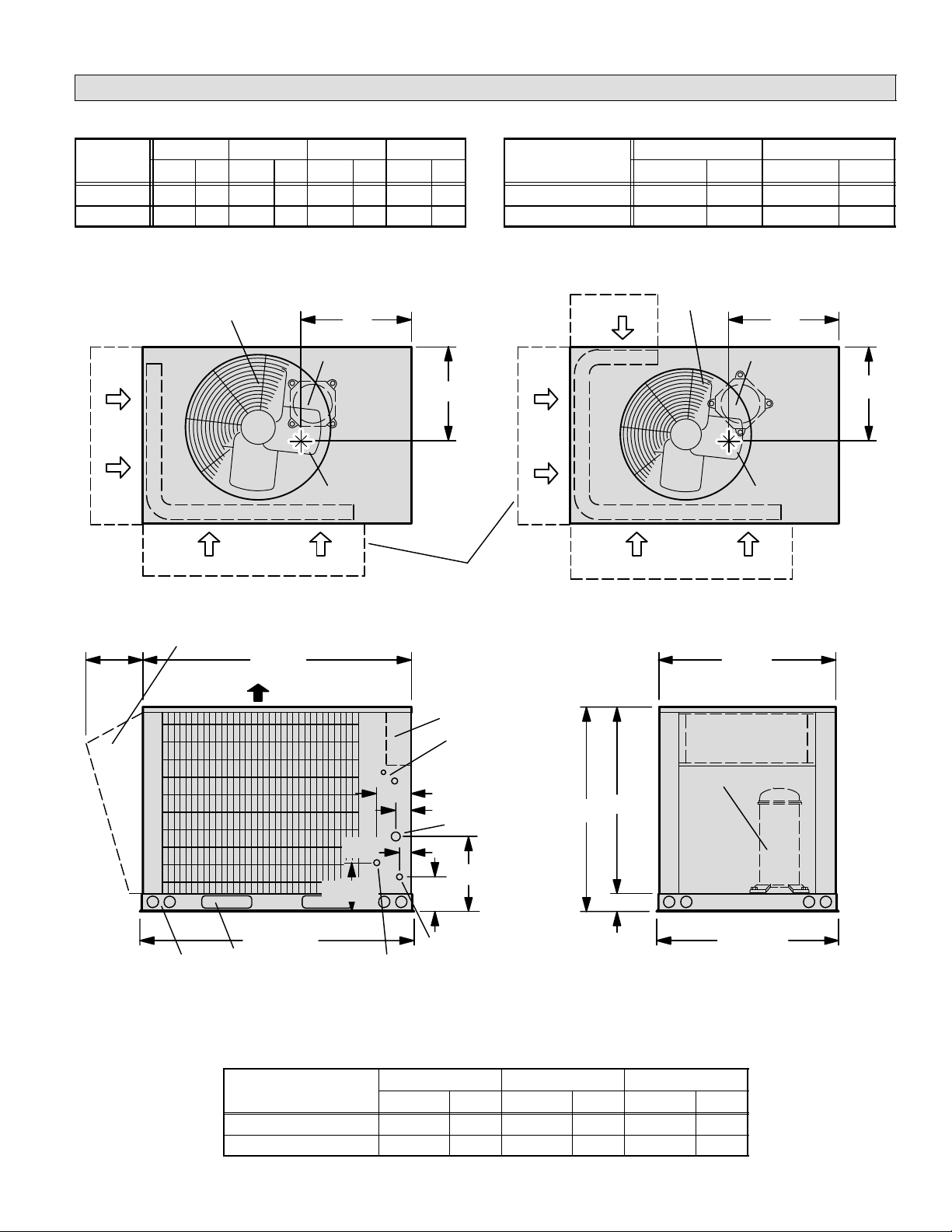
Field refrigerant piping consists of liquid and suction lines
exiting the condensing unit. You may bring piping into the
unit through either side. Remove the knockouts on the mul
lions and install the provided rubber grommets into the pip
ing holes. Remove the plugs from the liquid and suction
lines. Refer to table 1 for fieldfabricated refrigerant line
sizes for runs up to 50 linear feet (15 m).
Table 1
Refrigerant Line Sizes for Runs Up to 50 Linear Feet
Unit Liquid Line Suction Line
HS29−072 5/8 in.
(16 mm)
1−1/8 in.
(29 mm)
HS29−090 5/8 in.
(16 mm)
1−3/8 in.
(35 mm)
HS29−120 5/8 in.
(16 mm)
1−3/8 in.
(35 mm)
Refrigerant Line Brazing Procedure
1 − Cut the end of the refrigerant line square, keep it round,
protect it from nicks or dents, and debur it. (I.D. and
O.D.)
2 − Wrap a wet cloth around the liquid and suction valve
body when brazing to prevent possible heat damage to
the valve core and port.
3 − In the liquid line, install the filter drier (provided with the
unit) in an accessible area as close as possible to the
expansion device.
Refrigerant Line Limitations
You may install the unit in applications that have line set
lengths of up to 50 linear feet (15 m) with refrigerant line
sizes as outlined in table 1 (excluding equivalent length of
fittings). Size refrigerant lines from 50 to 100 linear feet (15
to 30 m) according to the the following section. Line lengths
greater than 100 feet (30 m) are not recommended.
Maximum suction lift must not exceed 70 linear feet (21 m)
and the maximum liquid head must not exceed 50 linear
feet (15 m).
When line lengths exceed 50 feet (15 m), install a liquid line
solenoid at the evaporator coil. In addition, use only expan
sion valves (RFC and captube expansion devices are not
acceptable).
NOTE − When refrigerant line solenoid valves are installed,
velocities should not exceed 300 fpm (1.5 m/s) in order to
avoid liquid line hammer.
Because additional refrigerant is necessary to fill the lines,
the likelihood of slugging is greatly increased if the lines are
over 50 feet (15 m). An incremental increase in liquid line
size results in a 40 to 50 percent increase in liquid refriger
ant to fill the line. Therefore, use the smallest liquid line size
possible.
All units are equipped with a low ambient (head pressure)
control to allow for cooling at an ambient condition of 0°F
(−18°C).
Pipe Sizing, Line Layout, and Design
[Line Set Lengths of 50 − 100 Linear Feet
(15 − 30 m)]
Create a a sketch of the system that shows the relative
locations of the condensing unit and the evaporator as well
as the length of the following:
D each piping segment
D elbows
D tees
D valves
Use this information to determine the equivalent length of
the piping run. Also, take note of any difference in the
elevation between the outdoor and indoor units. You must
consider vapor and liquid lift so that you can properly size
the pipe.
Liquid Line Function and Design
The liquid line must convey a full column of liquid from the
condenser to the metering device at the evaporator coil
without flashing. In order to ensure this, you must consider
the liquid line pressure drop and the pressure across the
expansion device and distributor.
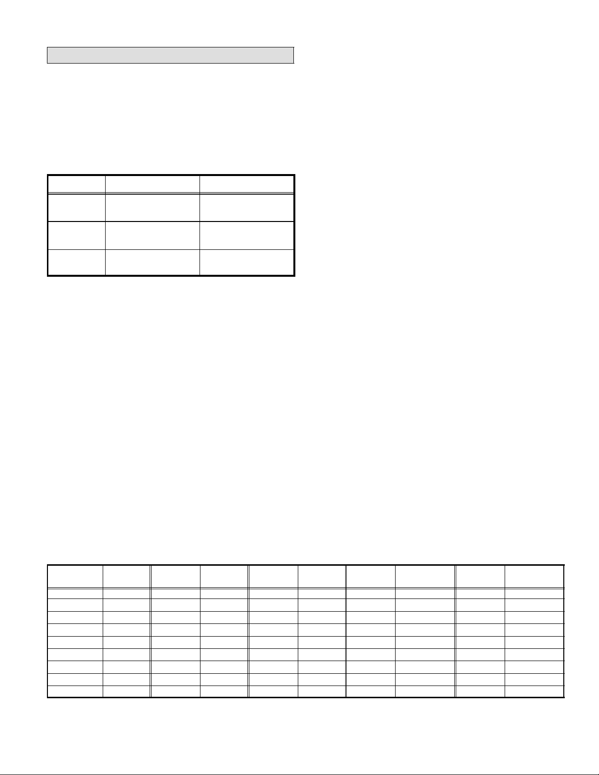
Table 2
HCFC22 Saturation Temperatures
(Condensing Temperatures at Different Pressures)
Temp.
°F (°C)
Pressure
psig (kPa)
Temp.
°F (°C)
Pressure
psig (kPa)
Temp.
°F (°C)
Pressure
psig (kPa)
Temp.
°F (°C)
Pressure
psig (kPa)
Temp.
°F (°C)
Pressure
psig (kPa)
−40 (−41) 0.6 (4.13) 18 (−8) 41.1 (283) 36 (2) 63.3 (436) 75 (24) 133.4 (920) 120 (49) 262.5 (1810)
−30 (−34) 4.09 (28.1) 20 (−7) 43.3 (299) 38 (3) 66.1 (456) 80 (27) 145.0 (1000) 125 (52) 280.7 (1936)
−20 (−28) 10.2 (70.3) 22 (−6) 45.5 (314) 40 (4) 69.0 (476) 85 (29) 157.2 (1084) 130 (54) 299.7 (2066)
−10 (−23) 16.6 (114) 24 (−4) 47.9 (330) 45 (7) 76.6 (528) 90 (32) 170.0 (1172) 135 (57) 319.6 (1514)
0 (−18) 24.1 (166) 26 (−3) 50.3 (347) 50 (10) 84.7 (584) 95 (35) 183.6 (1287) 140 (60) 340.3 (2346)
10 (−12) 32.9 (227) 28 (−2) 52.7 (363) 55 (13) 93.3 (643) 100 (38) 197.9 (1364) 145 (63) 362.0 (2496)
12 (−11) 34.9 (241) 30 (−1) 55.2 (381) 60 (16) 102.4 (706) 105 (41) 212.9 (1468) 150 (66) 384.6 (2651)
14 (−10) 36.9 (254) 32 (0) 57.8 (399) 65 (18) 112.2 (774) 110 (43) 228.6 (1576) 155 (68) 406.3 (2801)
16 (−9) 39.0 (269) 34 (1) 60.5 (417) 70 (21) 122.5 (841) 115 (46) 245.2 (1691) 160 (71) 433.3 (2987)

Page 11
HCFC22 Liquid Line Pressure Drop/Velocity
At 45°F Evaporating Temperature and 125°F Condensing Temperature
30
25
20
15
10
9
8
7
6
5
4
3
2
1.5
1.0
.9
.8
.7
10 9 8 7 6 5 4 3 2 1.5 1.0.9 .8 .7 .6 .5 .4 .3 .2
HCFC22 Liquid Line Pressure Drop (lbs./100 Feet)
COOLING CAPACITY (TONS)
30
25
20
15
10
9
8
7
6
5
4
3
2
1.5
1.0
.9
.8
.7
COOLING CAPACITY (TONS)
10 9 8 7 6 5 4 3 2 1.5 1.0 .9 .8 .7 .6 .5 .4 .3 .2
HCFC22 Liquid Line Pressure Drop (lbs./100 Feet)
NOTE − Shaded area represents unacceptable velocity range.
Figure 10
12.5
40 30 20 15
40 30 20 15
EXAMPLE:
10−TON UNIT
5/8 IN. O.D. LINE 4.25
PSIG DROP PER 100
FEET
275 FPM VELOCITY
To use this chart, first find the capacity (tons) on the left side of chart. To find the pipe size, proceed right to the smallest pipe
size. You can then determine the pressure drop (vertical at line) and velocity (diagonal lines) for the pipe size you selected.
For example, for (2) 7.5 ton units, select 5/8 in. O.D. line.

Page 12
Figure 10 illustrates the relationship between liquid line siz
ing, pressure drop per 100 feet, velocity range, and ton
nage. Remember, when using liquid line solenoid valves,
velocities should not exceed 300 fpm (1.5 m/s). Find the
cooling capacity on the left side of the chart in figure 10,
then proceed right to the smallest tube size that will not ex
ceed 300 fpm (1.5 m/s) velocity.
Table 3
Equivalent Length in Feet of Straight Pipe for
Valves and Fittings
Line
Size
O.D.
in.
Solenoid/
Globe
Valve
Angle
Valve
90°
Long*
Radius
Elbow
45°
Long*
Radius
Elbow
Tee
Line
Tee
Branch
3/8 7 4 0.8 0.3 0.5 1.5
1/2 9 5 0.9 0.4 0.6 2.0
5/8 12 6 1.0 0.5 0.8 2.5
3/4 14 7 1.3 0.6 0.9 3.0
7/8 15 8 1.5 0.7 1.0 3.5
11/8 22 12 1.8 0.9 1.5 4.5
13/8 28 15 2.4 1.2 1.8 6.0
15/8 35 17 2.8 1.4 2.0 7.0
21/8 45 22 3.9 1.8 3.0 10
25/8 51 26 4.6 2.2 3.5 12
NOTE − Long radius elbow. Multiply factor by 1.5 for short radius el
bow equivalent length.
Equipment that is above five tons in capacity typically oper
ates at a saturated condensing temperature of 125°F
(52°C) which corresponds to an operating pressure of 280
psig (1930 kPa). This equipment is designed to hold a
charge allowing 10°F (6°C) subcooling at 95°F (53°C) am
bient. Use the condensing temperature and the subcooling
to calculate the maximum allowable pressure drop as de
tailed below.
NOTE − 95°F (53°C) ambient is an arbitrary temperature
chosen to represent typical summer operating conditions
and the maximum allowable pressure drop. This tempera
ture (and the corresponding subcooling) will vary with re
gional climate.
Example − Calculating maximum allowable pressure
drop: Find the maximum allowable liquid line pressure
drop of a unit operating at 10°F (6°C) subcooling, 125°F
(52°C) condensing temperature and operating pressure of
280 psig (1931 kPa). Subtract 10°F (6°C) subcooling tem
perature from 125°F (52°C) condensing temperature to
equal 115°F (46°C) subcooled liquid temperature. This
corresponds with operating pressure of 245 psig (1689
kPa), which is the point at which flash gas will begin to form.
Subtract 245 psig (1689 kPa) subcooled pressure from 280
psig (1931 kPa) condensing pressure to find a maximum
allowable pressure drop of 35 psig (241 kPa).
To calculate the actual pressure drop in the liquid line, cal
culate the pressure drop due to friction and the pressure
drop due to vertical lift, then add the two:
Pressure drop due to friction
+
Pressure drop due to vertical lift
=Pressure drop in
the liquid line
You must consider the pressure drop due to friction in the
pipe, fittings, and fieldinstalled accessories such as driers,
solenoid valves, or other devices. Pressure drop ratings for
different pipe sizes are listed in figure 10. Pressure drop
ratings of fieldinstalled devices are typically supplied by
the manufacturer.
Pressure drop due to vertical lift (1/2 pound per foot) is
typically high and can be a limiting factor in the design of
the system.
The liquid refrigerant pressure must be sufficient to pro
duce the required flow through the expansion device. Liq
uid refrigerant (free of flash gas) should be delivered to the
expansion valve at a minimum of 175 psig (1207 kPa) to
ensure that the 100 psig (690 kPa) necessary to produce
full refrigerant flow is at the rated capacity.
Example − Liquid Line Pipe Sizing
Given: 10ton condensing unit on ground level with a
10ton evaporator on the third level above ground and a to
tal of 96 linear feet of piping. The unit is charged with 10°F
(6°C) subcooling at 125°F (52°C) condensing temperature
and an operating pressure of 280 psig (1930 kPa). Refer to
figure 11.
Find: Select tube size from figure 10.
given; 10 ton evaporator
10 ton condensing unit
with 10°f subcooling at 125°F
length of line − 96 ft.
find: liquid line size
10 ton
condensing unit
10 ton
evaporator
53 FT.
3 ft. 40 ft.
Liquid Line Sizing Example
Figure 11
filter/drier
4.25 psig
100 ft. x98 ft. = 4.17psig
Answer: 5/8 in. o.d. copper tubing can be used. Pressure loss does not exceed maximum
allowable pressure drop (6_F to 7_F subcooling will be available at the expansion valve)
and velocity is acceptable.
select a proposed tubing
size: 5/8 in. copper
solution:
pressure drop
cannot exceed
35 psig.
total pressure drop=
total friction losses + lift losses + filter/drier
total equivalent length =
linear length + equivalent length of fittings
two 90° long radius elbows @ 5/8 in. o.d. = 1ft. equiv. ft. ea.
total equivalent length = 98 ft.
total friction losses =
lift losses = 40 ft. x 1/ 2 psig per foot = 20 psig
total pressure drop = 20 psig + 4.17 psig + 1 psig = 25.17 psig
filter drop = 1 psig (by manufacturer)
Solution: For a 10−ton system, select a 5/8 inch O.D. line
with 4.25 psig (29 kPa) per 100 feet drop (per figure 10).
Now, calculate pressure drop due to friction and liquid lift to
determine if this is a good selection.

Page 13
The total friction drop for the application will include 96 feet
(29 m) of 5/8 inch O.D. pipe plus 1 equivalent foot per elbow
(two elbows) to equal 98 equivalent feet.
In a 10ton system, expect a 4.25 psig (29 kPa) drop per
100 feet of 5/8 inch O.D. copper (per figure 10). Multiply
4.25/100 by 98 equivalent feet to calculate the total friction
loss of 4.17 psig (28 kPa).
Add the pressure drop for vertical lift. HCFC22 pressure
drop is 1/2 psig per foot of vertical lift. In this application
which has a 40foot (12 m) vertical lift, we find that the pres
sure drop due to lift equals 20 psig (138 kPa).
Finally, add a filter drier to the liquid line which has a 1 psig
pressure drop (this number provided by manufacturer).
Add the three components of the pressure drop together to
find that the total pressure drop in this 5/8 inch line equals
25.17 psig (172 kPa) which is well within the acceptable
range. The 5/8 inch line, therefore, is a good selection be
cause it is well below the maximum allowable pressure
drop, is in a satisfactory velocity range, uses minimum re
frigerant, and provides sufficient pressure at the expansion
valve.
Alternative Sizing: Suppose you selected a 3/4 inch O.D.
line with 1.6 psig drop per 100 feet. Compute the total
equivalent length by adding the length [96 feet (29 m)], plus
the equivalent length of the fittings [from table 3, two 90°
ells at 1.25 feet .381 m) each]. The total equivalent length is
98.5 (30 M) feet. The total friction drop would have
been 1.6/100 multiplied by 98.5 = 1.57 psig. When you
add the pressure drop due to lift (20 psig) and the filter
drier (1 psig) the total pressure drop for 3/4 inch line
equals 22.57 psig.
Though the 3/4 inch line provides a lower pressure drop,
the larger diameter pipe will require more refrigerant; this
larger diameter will increase the risk of refrigerant slugging.
In addition, because the smaller line will be less costly, use
it instead of the larger line.
Suction Line Function and Design
The suction line returns refrigerant vapor and oil from the
evaporator to the compressor. Therefore, the design of the
suction line is critical. The design must minimize the pres
sure loss in order for the unit to operate at maximum effi
ciency. The design must also provide adequate oil return to
the compressor under any conditions.
Because the oil separates from the refrigerant in the evap
orator, the suction velocity must be adequate to sweep the
oil along the pipe. Horizontal suction lines require a mini
mum of 800 fpm velocity for oil entrainment. In order to
ensure oil entrainment, suction risers require a mini
mum velocity of 1200 fpm (1500 fpm is preferred) re
gardless of the length of the riser.
Figure 14 illustrates the relationship between the suction
line sizing, pressure drop, velocity, and cooling capacity.
Use this chart to determine suction line pressure drop and
velocity. As the pipe size increases, so does the velocity re
quired to ensure oil entrainment.
Vertical lift has no significant effect on system capacity.
However, systems lose approximately 1% of capacity for
every pound of pressure drop due to friction in the suction
line. In order to calculate capacity loss, you must first esti
mate pressure drop in the total equivalent length of the pip
ing run (refer to figure 14). Capacity ratings include the loss
for a 25foot refrigerant line. Therefore, subtract the pres
sure loss of 25 feet of piping from the total that you calcu
lated for your particular application. See figure 12.
Outdoor
Unit
Indoor
Unit
Determining Suction Line Capacity Loss
If Pressure Drop Is Known
Total Pressure Drop
For Equivalent Length
25 ft.
Line
Once Pressure Drop Is Found:
Btuh lost = 1% x (Total Press. Drop minus 25 ft.) x rated capacity
Figure 12
Total Pressure Drop
Minus Press. Drop in
25 ft. of Line
When an evaporator is located above or on the same level
as the condensing unit, the suction line must rise to the top
of the evaporator. This helps prevent liquid from migrating
to the compressor during the off cycle. Install traps at the
bottom of all vertical risers for migration protection during
the off cycle. See figure 13.
Outdoor
Unit
Indoor
Coil
Suction Piping
Indoor Coil Above or On Same Level with Outdoor Unit
Figure 13
Outdoor
Unit
Indoor
Coil
Vapor Line
Vapor Line
If equipment is on same level, the inverted trap should still be used
in order to prevent liquid migration to compressor during off cycle.
Trap
Raise Pipe
To Top Level Of
Coil
Install Traps At
Bottom Of
Each Riser
Horizontal suction lines should be level or slightly sloped
toward the condensing unit. The pipe must avoid any dips
or low spots that can collect oil. For this reason, use hard
copper, especially on long horizontal runs.
As with liquid line sizing, begin by making a sketch of the
layout complete with fittings, driers, valves etc. Measure
the length of each line and determine the number of ells,
tees, valves, driers etc. Add the equivalent length of fittings
(table 3) to length of pipe to get the total equivalent length
which is used to determine friction loss. Again, refer to
manufacturer’s data for pressure drop information on ac
cessory components. You must consider the resulting
pressure drop.

Page 14
HCFC22 Suction Line Pressure Drop/Velocity Per 100 Feet Of Line
At 45°F Evaporating Temperature and 125°F Condensing Temperature
30
25
20
15
10
9
8
7
6
5
4
3
2
1.5
1.0
.9
.8
.7
10 9 8 7 6 5 4 3 2 1.5 1.0 .9 .8 .7 .6 .5 .4 .3 .2
HCFC22 Suction Line Pressure Drop (lbs./100 Feet)
COOLING CAPACITY (TONS)
30
25
20
15
10
9
8
7
6
5
4
3
2
1.5
1.0
.9
.8
.7
COOLING CAPACITY (TONS)
10 9 8 7 6 5 4 3 2 1.5 1.0 .9 .8 .7 .6 .5 .4 .3 .2
HCFC22 Suction Line Pressure Drop (lbs./100 Feet)
NOTE − Shaded area denotes unacceptable velocity range.
Figure 14
40 30 20 15
40 30 20 15
EXAMPLE: 10 TON UNIT
13/8 IN. O.D. LINE
3.3 PSIG DROP PER 100 FEET
2400 FPM VELOCITY
12.512.5
To use this chart, first find capacity (tons) on left side of chart. To find the pipe size, proceed right to the smallest pipe size. You
can then determine the pressure drop (vertical line) and velocity (diagonal lines) for the pipe size you selected. For example, for
10 ton unit, select 13/8 in. O.D. line.

Page 15
Example −− Suction Line Pipe Sizing
Given: 71/2 ton condensing unit with evaporator lower
than condenser. Application includes 82 linear feet of pip
ing and 4 ells. There is a 20foot vertical lift and 62 feet of
horizontal run. Refer to figure 15.
Find: Select tube size from figure 14.
Solution: Select a 11/8 inch O.D. line with 6 psig per 100
feet pressure drop and 2900 fpm velocity. Now, calculate
pressure drop due to the friction to determine if this is a
good selection.
Figure 15
Indoor Coil
Example Indoor Coil Below Condenser
Suction Line
Suction Riser
Oil Trap
20 FT.
2 FT.
60 FT.
From table 3, four ells at 1.8 equivalent feet each equals
7.2 equivalent feet. When added to the 82 feet of pipe, the
total equivalent feet becomes 89.2 feet (round up to 90
feet).
Multiply 6/100 by 90 equivalent feet to calculate total friction
loss of 5.4 psig.
Use figure 14 to calculate the pressure drop in 25 feet of 11/8
inch line. Multiply 6/100 by 25 feet to calculate friction loss of
1.5 psig. This loss has already been included in the capacity,
so it should be subtracted from the total.
The Btuh capacity lost in the total equivalent length" of the
refrigerant line (using figures 12 and 14) equals 1% X (5.4 −
1.5) X 90,000 = 3510.
Btuh lost = 0.01 x (3.9) x 90,000 = 3510
The capacity loss for the line selected is approximately
3.9%.
The preceding calculation shows that this is a workable
system, but the line will lose capacity and efficiency.
Alternative Sizing: Using the same (71/2 ton) example,
this time select 13/8 inch O.D. line. A 13/8 inch O.D. line
with 2 psig per 100 feet pressure drop has 1760 fpm veloc
ity. Now calculate the pressure drop due to friction loss to
determine if this is a better selection.
From figure 3, four ells at 2.4 equivalent feet each equals
9.6 equivalent feet. When added to the 82 feet of pipe, the
total equivalent feet becomes 91.6 feet (round up to 92
feet).
Multiply 2/100 by 92 equivalent feet to calculate total fric
tion loss of 1.8 psig.
Use figure 14 to calculate the pressure drop in 25 feet of 13/8
inch line. Multiply 2/100 by 25 feet to calculate friction loss of
0.5 psig. This loss has already been included in the capacity,
so it should be subtracted from the total.
The Btuh capacity lost in the total equivalent length" of the
refrigerant line (using figures 12 and 14) equals 1% X (1.8 −
0.5) X 90,000 = 1170.
Btuh lost = 0.01 x (1.3) x 90,000 = 1170
The capacity loss for the line selected is approximately
1.3%.
The conditions in this example will allow either 11/8 inch or
13/8 inch suction line to be used, since capacity loss is
minimized and velocity is sufficient to return oil to the com
pressor.
Double Suction Risers
If the condensing unit is equipped to run with a capacity re
duction of less than 50 percent, suction lines can generally
be sized in accordance with the previous sections. If the
suction velocity is high enough to entrain oil when the unit is
operating at reduced capacity, double suction risers are
generally unnecessary.
However, suction−type hot gas bypass kits reduce the
unit’s capacity and suction line refrigerant velocity, and
therefore, double suction risers are required in these
cases.
In general, double suction risers are necessary any time the
minimum load on the compressor does not create sufficient
velocity in vertical suction risers to return oil to the compres
sor. Double suction risers are also generally required any
time the pressure drop or velocity in a single suction riser is
excessive.
Figure 16 shows a simplified example of a double suction
riser installation. A trap is installed between the two risers
as shown. During partial load operation when gas velocity
is not sufficient to return oil through both risers, the trap
gradually fills with oil until the second riser is sealed off.
When this happens, the vapor travels up the first riser only.
With only the first riser being used, there is enough velocity
to carry the oil. This trap must be close coupled to limit the
oil holding capacity to a minimum. Otherwise, the trap
could accumulate enough oil on a partial load to seriously
lower the compressor crankcase oil level.

Page 16
The second suction riser must enter the main suction line
from the top to avoid oil draining down the second riser dur
ing a partial load.
Figure 16
Evaporator
Condensing
Unit With
Hot Gas
Bypass
Horizontal Suction Line Is Sized
To Handle Total Load.
In The Vertical Portion Of The Line,
A Smaller Line Is Sized To Handle
The Reduced Capacity.
Typical Double Suction Riser
Double Suction
Riser
The Remaining Line Is Sized To
Handle The Remaining Capacity
Figure 17 illustrates a typical double−suction riser
construction.
Figure 17
Double Suction Riser Construction
Method A"
90_Street Ell
Method
Method B"
UBEND
METHOD
A" B"
Vapor Line
From Air Handler
(Slope to Compressor)
Reducing Tee
Ubend
Vapor Line
To Compressor
A" B"
Vapor Line
From Air Handler
(Slope to Compressor)
Reducing
Te e
90° Street
Elbow
90° Street Elbow
Reducing Tee
Street Ell
Vapor Line
To Compressor
Figure 18
Evaporator
10 Ton
Condensing Unit
With Hot Gas
Bypass
15 FT.
40 FT.
2 FT.
Double Suction Riser Example
Double Suction
Riser
A
B
Example −− Double Suction Riser Sizing
Given: 10ton condensing unit with hot gas bypass (run
around type). Matched evaporator is located below the
condensing unit. Piping will require 57 (linear) feet of pipe
(figure 18). Construction without double suction risers will
only require 2 ells.
Find: Select tube sizes for horizontal runs and risers (fig
ure 14). Determine if double suction risers are necessary.
Size the double suction riser for proper system perfor
mance.
Solution: Size each segment based on the tons of refrig
erant that will flow in the segment.
Full load capacity = 10 tons. Minimum load capacity is 35%
of 10 tons = 3.5 tons. The difference between full capacity
and partial load capacity is 6.5 tons.
From figure 14, select a pipe size for full load capacity. A
13/8 inch O.D. pipe with 3.3 psig drop per 100 feet and
2400 fpm velocity has been selected. Now, by using figure
14, find the velocity for the selected pipe size at part load
capacity. The part load velocity is approximately 850 fpm.
850 fpm is sufficient to return oil in horizontal runs but not in
vertical risers.
If you try to size this system by simply reducing the riser
size to 11/8 inch, you would find the velocity in the riser to
be excessive (3800 fpm) when the system is operating at
full capacity. As a result of these obstacles, this system will
require the construction of double suction risers. Construc
tion of double suction riser will require five ells and two tees
total for a system.
Size small riser
(Riser carrying smallest part of load)
The unit produces 3.5 tons capacity at minimum load. Se
lect from figure 14 a 7/8 inch O.D. line (smallest line with
acceptable velocity). When operating at 3.5 tons capacity,
this line will operate at 2500 fpm and will produce 6 psig
drop per 100 feet.

Page 17
Size large riser
(Riser carrying largest part of load)
The larger line carries 6.5 tons capacity at full load. Select
from figure 14 a 11/8 inch O.D. line (smallest line with ac
ceptable velocity). When operating at 6.5 tons capacity,
this line will operate at 2500 fpm and will produce 4.5 psig
drop per 100 feet.
Putting the Segments Together
Next, you must determine if the line sizes you selected will
result in satisfactory pressure drop between the condens
ing unit and the evaporator.
Start by finding the total equivalent feet of the large (B) ris
er. See figure 18. Fifteen feet of pipe, plus two tees (branch
side of tee at 4.5 equivalent feet each), plus four ells (1.8
equivalent feet each) = 31.2 equivalent feet length:
15 + 9 (two 4.5 foot tees) + 7.2 (four 1.8 foot ells ) = 31.2
Now, find the total equivalent feet of the small (A) riser. See
figure 18. Fifteen feet of pipe, plus one ell (1.5 equivalent
feet), plus one tee (branch side of tee at 3.5 equivalent
feet), plus one tee (line side of tee at 1.0 equivalent feet) =
21.0 equivalent feet length:
15 + 1.5 + 3.5 + 1.0 = 21.0
Use the total equivalent length of each riser to compute the
pressure drop of each riser. For the large (B) riser, 11/8
inch O.D. suction line with 6.5 tons capacity has 4.5 psig
drop per 100 feet. Multiply (4.5/100) by 31.2 equivalent feet
to calculate the total friction loss of 1.4 psig.
(4.5 100) X 31.2 = 1.4
For the small (A) riser, a 7/8 inch O.D. suction line with 3.5
tons capacity has 6 psig drop per 100 feet. Multiply (6/100)
by 21 equivalent feet to calculate the total friction loss of
1.26 psig:
(6 100) X 21 = 1.26 psig.
The total pressure drop for the riser is equal to the average
of the pressure drop in both risers:
1.4 (B riser drop) + 1.26 (A riser drop) = 2.66
2.66 2 = 1.33 (average pressure drop through A
and B risers)
Find the pressure drop for the horizontal run of pipe. A
13/8 inch pipe at 10 tons capacity and has 3.3 psig drop
per 100 feet. Multiply 3.3/100 by 61 equivalent feet to cal
culate the total friction loss of 2.01 psig:
3.3 100 X 61 = 2.01
Add the pressure drop through the risers to the pressure
drop through the horizontal run to find the total pressure
drop for the system:
2.01 psig (horiz. run) + 1.33 psig (avg. riser) = 3.34
Use figure 14 to calculate the pressure drop in 25 feet of
13/8 inch line. Multiply 3.3/100 by 25 feet to calculate the
friction loss of 0.825 psig.
3.3 100 X 25 = 0.825
The Btuh capacity lost in the total equivalent length"
of the refrigerant line (using figures 12 and 14) = 1% x
(3.34 − 0.825) x 120,000:
Btuh lost = 0.01 x (2.515) x 120,000 = 3018
Capacity loss for the line selected is approximately 2.5 per
cent.
Service Valves
The liquid line and suction line service valves and gauge
ports are accessible inside the unit. These gauge ports are
used for leak testing, evacuating, charging, and checking
the charge. Condensing unit, lines, and evaporator need to
be evacuated.
Liquid Line Service Valve
HS29−072/090/120 units use the liquid line service valve
shown in figure 19. A Schrader valve core is factory
installed. A service port cap is supplied to protect the
Schrader valve from contamination and serve as the pri
mary leak seal.
Accessing the Schrader Valve:
1 − Remove service port cap with an adjustable wrench.
2 − Connect gauge to the service port.
3 − When testing is complete, replace service port cap.
Tighten finger tight, then tighten an additional 1/6 turn.

Page 18
Liquid And Suction Line Service Valve
(Valve Open)
Schrader
valve
service
port
service port
cap
insert hex
wrench here
to indoor coil
to outdoor coil
stem cap
Schrader valve open
to line set when valve is closed
(front seated)
service
port
service
port cap
stem cap
insert hex
wrench here
Liquid And Suction Line Service Valve
(Valve Closed)
(valve front seated)
to outdoor coil
to indoor coil
Figure 19
Opening the Liquid Line Service Valve:
1 − Remove stem cap with an adjustable wrench.
2 − Use a service wrench with a hex−head extension to
back the stem out counterclockwise as far as it will go.
3 − Replace the stem cap. Tighten finger tight, then tighten
an additional 1/6 turn.
WARNING
Do not attempt to backseat this valve. Attempts to
backseat this valve will cause the snap ring to ex
plode from valve body under pressure of refrigerant.
Personal injury and unit damage will result.
Closing the Liquid Line Service Valve:
1 − Remove stem cap with an adjustable service wrench.
2 − Using a service wrench with a hex−head extension, turn
the stem clockwise to seat the valve. Tighten firmly.
3 − Replace the stem cap. Tighten finger tight, then tighten
an additional 1/6 turn.
All units are equipped with a full service ball valve, as
shown in figure 20. One service port that contains a
Schrader valve core is present in this valve. A cap is also
provided to seal off the service port. The valve is not re
buildable so it must always be replaced if failure has oc
curred.
Opening the Suction Line Service Valve: 090 and 120
1 − Remove the stem cap with an adjustable wrench.
2 − Using a service wrench, turn the stem counterclock
wise for 1/4 of a turn.
3 − Replace the stem cap and tighten it firmly.
Closing the Suction Line Service Valve: 090 and 120
1 − Remove the stem cap with an adjustable wrench.
2 − Using a service wrench, turn the stem clockwise for 1/4
of a turn.
3 − Replace the stem cap and tighten firmly.
Suction Line (Ball Type) Service Valve
(Valve Open)
Schrader Valve
Service Port
Stem Cap
Stem
Use Adjustable Wrench
Rotate Stem Clockwise 90° To Close
Rotate Stem Counterclockwise 90° To Open
Ball
(Shown Open)
To Outdoor Coil
To Indoor Coil
Service Port Cap
Figure 20
Leak Testing
After you have connected the line set to the indoor and out
door units, check the line set connections and indoor unit
for leaks.
WARNING
Never use oxygen to pressurize refrigeration or air
conditioning system. Oxygen will explode on con
tact with oil and could cause personal injury. When
using a high pressure gas such as nitrogen or CO2
for this purpose, be sure to use a regulator that can
control the pressure down to range of1 to 2 psig (6.9
to 13.8 kPa).
Using an Electronic Leak Detector or Halide
1 − With both manifold valves closed, open the valve on
the HCFC22 cylinder (vapor only).

Page 19
2 − Open the high pressure side of the manifold to allow
the HCFC22 into the line set and indoor unit. Weigh in
a trace amount of HCFC22. [A trace amount is a maxi
mum of 2 ounces (57 g) refrigerant or 3 pounds (31
kPa) pressure]. Close the valve on the HCFC22 cylin
der and the valve on the high pressure side of the man
ifold gauge set. Disconnect HCFC22 cylinder.
3 − Connect a cylinder of nitrogen (that has a pressure
regulating valve) to the center port of the manifold
gauge set.
4 − Connect the high pressure hose of the manifold gauge
set to the service port of the suction valve.
NOTE − Normally the high pressure hose is connected
to the liquid line port. However, connecting it to the suc
tion port more effectively protects the manifold gauge
set from high pressure damage.
5 − Adjust the nitrogen pressure to 150 psig (1034 kPa).
Open the valve on the high side of the manifold gauge
set which will pressurize the line set and indoor unit.
6 − After a few minutes, open a refrigerant port to ensure
that the amount of refrigerant you added is large
enough to be detected. (Amounts of refrigerant will
vary with line lengths.) Check all joints for leaks. Purge
the nitrogen and HCFC22 mixture. Correct any leaks
and recheck.
Evacuation & Dehydration
IMPORTANT
Units are shipped with a holding charge of dry air
and helium which must be removed before the unit
is evacuated and charged with refrigerant.
Evacuating the system of noncondensables is critical for
the unit to operate properly. Noncondensables are gases
that will not condense under temperatures and pressures
which are present while an air conditioning system is oper
ating. Noncondensables and water vapor combine with re
frigerant to produce substances that corrode copper piping
and compressor parts.
1 −Remove the suction valve actuation/stem cap. Turn
the stem unit it is fully open. To open the liquid valve,
remove cap and turn the valve stem until it is fully open.
2 −Connect the manifold gauge set to the service valve
ports as follows:
D low pressure gauge to suction line service valve
D high pressure gauge to liquid line service valve
3 −Purge the system of dry air, helium, or nitrogen.
IMPORTANT
Never use compliant scroll compressors (as with
any refrigerant compressor) to evacuate a refrigera
tion or air conditioning system!
NOTE − Use a temperature vacuum gauge, mercury
vacuum, or thermocouple gauge. The usual Bourdon
tube gauges are inaccurate in the vacuum range.
4 −Connect the vacuum pump (with vacuum gauge) to the
center port of the manifold gauge set.
5 −Open both manifold valves and start the vacuum pump.
6 −Evacuate the line set, outdoor unit, and the indoor unit
to an absolute pressure of 23 mm (23,000 microns) of
mercury or approximately 1 inch of mercury. During the
early stages of evacuation, close the manifold gauge
valve at least once to determine if there is a rapid rise in
absolute pressure. A rapid rise in pressure indicates a
relatively large leak. If this occurs, repeat the leak test.
NOTE − The term absolute pressure means the total
actual pressure within a given volume or system,
above the absolute zero of pressure. Absolute pres
sure in a vacuum is equal to atmospheric pressure mi
nus vacuum pressure.
7 −When the absolute pressure reaches 23 mm (23,000
microns) of mercury, do the following:
Dclose the manifold gauge valves
Dturn off the vacuum pump
Ddisconnect the manifold gauge center port hose
from the vacuum pump
Attach the manifold center port hose to a nitrogen cyl
inder with the pressure regulator set to 150 psig (1034
kPa) and purge the hose. Open the manifold gauge
valves to break the vacuum in the line set and indoor
unit. Close the manifold gauge valves.
CAUTION
Danger of Equipment Damage.
Avoid deep vacuum operation. Do not use compres
sors to evacuate a system.
Extremely low vacuums can cause internal arcing
and compressor failure.
Damage caused by deep vacuum operation will void
warranty.
8 −Shut off the nitrogen cylinder and remove the manifold
gauge hose from the cylinder. Open the manifold
gauge valves to release the nitrogen from the line set
and the indoor unit.

Page 20
9 −Reconnect the manifold gauge to the vacuum pump,
turn the pump on, and continue to evacuate the line
set, indoor unit, and outdoor unit. Continue to evacuate
the line set until the absolute pressure does not rise
above .5 mm of (500 microns) mercury within a 20 min
ute period after you have turned off the vacuum pump
and closed the manifold gauge valves.
10 − When the absolute pressure requirement above has
been met, disconnect the manifold hose from the vac
uum pump. Connect it to an upright cylinder of
HCFC22 refrigerant.
11 − Open the manifold gauge valves to break the vacuum
in the line set and indoor unit.
12 − Close manifold gauge valves and shut off the
HCFC22 cylinder and remove the manifold gauge set.
Start−Up
Cooling Start−Up
IMPORTANT
Crankcase heater should be energized 24 hours be
fore unit start−up to prevent damage to the compres
sor as a result of slugging.
1 − Verify that the indoor blower is operating.
2 − Rotate the fan to check for frozen bearings or binding.
3 − Inspect all factory and field−installed wiring for loose
connections.
4 − Check the voltage supply at the disconnect switch. The
voltage must be within the range listed on the unit
nameplate. If it is not, do not start the equipment until
you have consulted the power company and the volt
age condition has been corrected.
5 − To start the unit, set the thermostat for a cooling de
mand, turn on the power to the blower, and close the
condensing unit disconnect switch.
6 − Recheck the unit voltage while the unit is running. The
power must be within the range shown on the unit
nameplate. Check the amperage draw of the unit, and
refer to the unit nameplate for correct running amps.
Three−Phase Compressor Rotation
Threephase scroll compressors must be phased sequen
tially to ensure that the compressor rotates and operates
correctly. When the compressor starts, a rise in discharge
and drop in suction pressures indicate proper compressor
phasing and operation. If discharge and suction pressures
do not perform normally, follow the steps below to correctly
phase in the unit.
1 − Disconnect the power to the unit.
2 − Reverse any two field power leads to the unit.
3 − Reconnect the power to the unit.
The discharge and suction pressures should operate at
their normal startup ranges.
NOTE − Compressor noise level will be significantly higher
when phasing is incorrect. The unit will not provide cooling
when compressor is operating backwards. Continued
backward operation will cause the compressor to cycle on
internal protector.
This manual suits for next models
2
Table of contents
Other Lennox Air Compressor manuals
Popular Air Compressor manuals by other brands

nuair
nuair Squirrel Instructions for use manual

Central Pneumatic
Central Pneumatic 68067 Owner's manual & safety instructions

Black Ridge
Black Ridge BRC120 instructions

Toolshop
Toolshop 207-1545 Operator's manual

Central Pneumatic
Central Pneumatic 95275 Owner's manual & safety instructions

ALLPOWER
ALLPOWER APC4408 Operator's manual