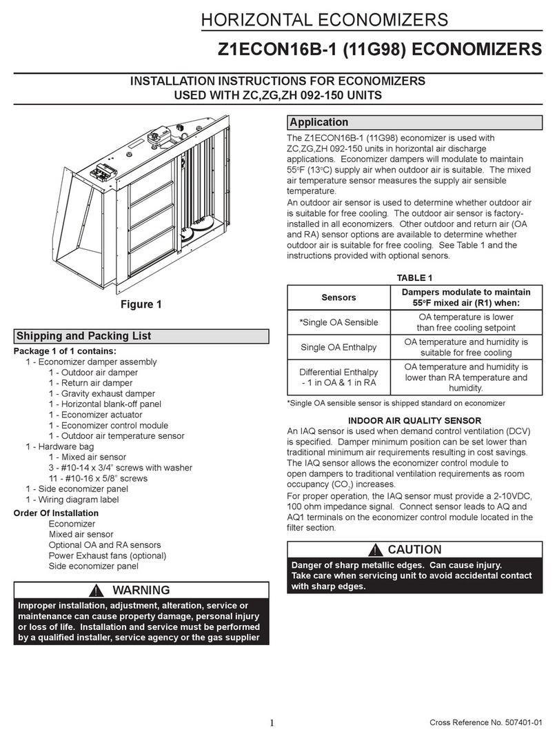
Lennox iHarmony 10C16 User manual

CONTROLS
KITS AND ACCESSORIES
©2018 Lennox Industries Inc.
Dallas, Texas USA iHarmony®Zoning System
507132-03
6/2018
Supersedes 4/2018
INSTALLATION INSTRUCTIONS FOR IHARMONY ZONING SYSTEM (10C16)
THIS MANUAL MUST BE LEFT WITH THE OWNER
FOR FUTURE REFERENCE
WARNING
Installation and service must be performed by a licensed
professional HVAC installer (or equivalent) or a service
agency.
Shipping and Packing List
Kit (10C16) consists of the following:
1 - Damper control module assembly
1 - Discharge air temperature sensor (88K3801)
4 - Screws (#6-20 x ⅜, Phillips pan-head type 25)
1 - Freeze-stat jumper (pre-installed on damper control)
1 - Warranty sheet
General
The damper control module is compatible with the
following Lennox equipment:
• iComfort Wi-Fi® thermostat (10F81) or (88W58) with
software version 2.13 or higher
• iComfort S30 Ultra Smart Thermostat (12U67)
• Lennox communicating variable speed or variable
capacity (modulating) indoor and two-stage or variable
capacity (modulating) outdoor units.
• Lennox communicating variable speed indoor unit and
communicating or non-communicating (conventional)
single-stage outdoor unit (two zones maximum
supported).
• Lennox communicating variable speed indoor unit and
communicating or non-communicating (conventional)
two-stage outdoor unit (four zones maximum supported).
Table of Contents
Shipping and Packing List........................................... 1
General .......................................................................... 1
Required Items Sold Separately.................................. 2
Recommended Items Sold Separately ....................... 2
Zoning Components..................................................... 2
Transformer Phasing............................................................. 2
Dampers ............................................................................... 3
Discharge Air Temperature Sensor - DATS .......................... 3
DATS Temperature / Resistance Chart................................. 4
Pressure Switch.................................................................... 4
Staged Heat Pump Units ...................................................... 4
Modulating Heat Pump Unit (XP20 and XP25)..................... 4
Freezestat (Optional) ............................................................ 5
Setup and Conguration.............................................. 5
Damper Control Module Jumper Settings, LEDs and
Connections.......................................................................... 5
Lennox Communicating Indoor Control Link Settings........... 6
iComfort Wi-Fi Thermostat - Installer Zoning
Control Settings............................................................ 8
Zoning Control Parameters................................................... 8
Zoning System Parameters .................................................. 8
To Edit and Test Airow Per Zone......................................... 9
Recording Airow Information............................................... 9
iComfort S30 Thermostat - Installer Zoning
Control Settings.......................................................... 10
Zoning Control Parameters................................................. 10
Zoning System Parameters ................................................ 10
Zoning Sequence of Operations ............................... 11
Heating / Cooling Changeover.............................................11
Damper Operation ...............................................................11
Dual-fuel Operation............................................................. 12
Emergency Heat Operation - Heat Pump Systems ........... 12
Humidity Control ........................................................ 12
Soft Disable................................................................. 12
iComfort Wi-Fi ..................................................................... 12
iComfort S30 Thermostat.................................................... 12
Minimum CFM for Zoning System with Variable
Speed Blower Motors................................................. 13
Zoning Alert Codes .................................................... 14

2
Required Items Sold Separately
The following items are also required for the zoning
system to operate:
1. In-zone thermostats (catalog number 10C17) — are
required for zones 2 through 4. Zone 1 is controlled
by the Lennox communicating thermostat. Works with
both iComfort Wi-Fi and S30 thermostats.
2. iHarmony Zone Sensor (17A30) which only works
with system controlled by an iComfort S30 thermostat.
3. Zone damper transformer, see “Table 1. Zone Damper
Transformer Selection Chart” for correct size.
4. Zone dampers — recommended zone dampers are
spring-open and power-close but you may also use
power-open and spring-close, or power-open and
power-close. Modulating dampers are not supported.
5. Optional freezestat, see “Table 4. Available
Freezestats” on page 5 for available freezestats
based on tubing sizes.
6. Fasteners to install the damper control module.
7. Heat Pump Applications Only: HFC-410A high
pressure switch (550PSI) (27W13) and valve
depressor tee (87071) are required.
IMPORTANT
Heat Pump Systems Only: Do not use jumper for
pressure switch terminals at the damper control module.
System will not function properly without pressure switch
installed.
Zone Damper Transformer
The zone dampers are powered by a eld−provided
24VAC transformer. Zone dampers require 6 to 12VA
each depending on zone damper used. The zone damper
transformer must have an adequate VA rating to serve all
components (see recommendations in following table).
The damper control module and three in-zone thermostats
require a total of 6VA to operate.
Table 1. Zone Damper Transformer Selection
Chart
Catalog
Number Size Description VA LOAD =
10P17 40VA
120 / 208
240VAC,
24VAC
Damper VA x number
of dampers + 6VA
(damper control
module + 3 in-
-zone thermostats) =
damper transformer
VA requirement.
10P87 50VA
12P61 75VA
83P74 - Electrical Box (4-in. Square)
Recommended Items Sold Separately
Lennox recommends for furnace applications the use of air
bafes to help in mixing the supply air for better Discharge
Air Temperature Sensor accuracy.
Table 2. Recommended Air Bafes for Furnaces
Furnace Width Type Catalog Number
B13X59
C 13X60
D 13X62
Zoning Components
Transformer Phasing
The indoor unit and zone damper transformers must be
in-phase since both are connected to the damper control
module. Follow the instructions below for phasing both
transformers.
1. Connect the damper control module indoor R and Cto
the indoor unit Rand C.
2. Connect the external 24VAC transformer to the damper
control module DMPR XFMR R and Cterminals.
3. Measure voltage between the damper control module
indoor Rand DPMR XFMR R terminals.
• In-phase voltage will be less than 10VAC.
• Out-of-phase voltage will be greater than 40VAC.
If voltage is greater than 40VAC, swap external
24VAC transformer (DMPR XFMR R and C) wires.
Ci−i+R
INDOOR
DMPR
XFMR
SYS
XFMR
iComfort -enabled
Furnace or Air
Handler
Ci−i+R
External 24VAC
Transformer
R
Damper Control
Module
Volt Meter
C
RC
DMPRXFMR
Figure 1. Conrming Correct Transformer Phasing
(Polarity)

3
Dampers
See table 1 to determine the minimum damper transformer
VA requirements based on the number of zones being
installed. If extended zone dampers are used then see
gure 2 for damper, transformer and zone relay wiring
requirements.
Refer to the iHarmony® Zoning System Product
Specication for ordering dampers and other various
components.
Once the damper control module has been installed and
the system energized, the damper control module will
automatically populate the thermostat commissioning
screens. All zone CFM settings will be selected from
commissioning screens for continuous blower and both
heating / cooling blower operations. Testing CFMs for
each or all zones may also be performed.
1. The extended damper transformer will only supply
power to extended dampers and relay contacts.
2. The system transformer powers the relay coils (0.4VA
each).
3. Combined load of damper transformer (see “Table 1.
Zone Damper Transformer Selection Chart” on page
2) and add 0.4VA per zone relay to determine the
minimum damper transformer VA requirements. Total
VA requirements should not exceed 60VA.
NOTE: Connections illustrated here are for the Lennox
recommended spring-open/power-close dampers.
The connections would be different for other
dampers.
NOTE: Use Lennox Part catalog number 56L68 for zone
relays 1 through 4. (Pulse Control Relay, SPDT, 1
N.O. and 1 N.C., 24VAC)
MAIN
POWER
MAIN
POWER
DAMPER TRANSFORMER – POWERS DAMPER CONTROL MODULE,
Figure 2. Damper and Extended Damper Wiring
Diagram
Discharge Air Temperature Sensor - DATS
The included discharge air temperature sensor
(88K38) monitors the supply air. “Figure 4. Discharge
Air Temperature Sensor Installation (Typical Up-Flow
Furnace)” shows the discharge air temperature sensor.
This electronic sensor’s probe is inserted into the discharge
air plenum (see “Figure 3. Discharge Air Temperature
Sensor Installation - DATS”) to gather air temperature
data for the zone control module.
• When possible, position the sensor some distance away
from the coil rather than in the immediate coil area.
• The DATS should be located at least 19 inches above
the air handler unit and 10 inches above cooling coil
with a furnace.
• Locate the tip of the sensor 1/2 the depth of the plenum,
and centered over the discharge airow, side- to -side in
the discharge plenum
• Fasten the sensor bracket to the plenum with two self-
tapping sheet metal screws.
• Connect wires to DATS on damper control module, NOT
on the Lennox communicating indoor unit control.
NOTE: FOR UNITS WITH HUMIDITROL—Discharge air
sensor temperature (DATS) MUST be located on
the output side of the EDA (if used; see Humiditrol
Zoning Accessory Installation 505,337M).
IMPORTANT
If the DAT sensor has failed, shorted or not installed,
iHarmony will only operate in central mode. This mode is
also indicated by the DCM central mode LED being on.
There is no notication by the thermostat for this issue.
Figure 3. Discharge Air Temperature Sensor
Installation - DATS
coil
FURNACE
FRONT
VIEW
1/2
the width
of the
plenum
10 (254)
AIR HANDLER
SIDE VIEW
ECB
Electric
Heat
Strips
PLENUM
SENSOR
MOUNTING
DETAIL
19
(486)
Damper Control Module
Figure 4. Discharge Air Temperature Sensor
Installation (Typical Up-Flow Furnace)

4
DATS Temperature / Resistance Chart
Table 3. DATS Temperature / Resistance Chart
Sensor
°C °F (ohm)
VDC
(Volts)
Sensor
°C °F (ohm)
VDC
(Volts)
-6.6 20 46,134 1.513 46.2 115 4,169 0.304
-3.9 25 39,869 1.425 49.0 120 3,749 0.277
-1.1 30 34,520 1.335 51.8 125 3,368 0.252
1.7 35 29,936 1.247 54.5 130 3,037 0.229
4.4 40 26,104 1.161 57.3 135 2,750 0.209
7.2 45 22,764 1.077 60.0 140 2,489 0.191
10.1 50 19,842 0.993 62.8 145 2,250 0.174
12.8 55 17,406 0.916 65.7 150 2,033 0.158
15.6 60 15,294 0.842 68.5 155 1,847 0.145
18.4 65 13,442 0.772 71.3 160 1,678 0.132
21.2 70 11,849 0.706 73.9 165 1,536 0.121
23.9 75 10,501 0.647 76.8 170 1,397 0.111
26.7 80 9,282 0.589 79.7 175 1,272 0.101
29.5 85 8,233 0.537 82.2 180 1,170 0.094
32.3 90 7,322 0.489 85.1 185 1,070 0.086
35.0 95 6,523 0.445 87.8 190 982 0.079
37.8 100 5,819 0.405 90.8 195 895 0.072
40.6 105 5,193 0.368 93.4 200 829 0.067
43.4 110 4,654 0.335
Pressure Switch
(Required for heat pump applications.)
NOTE: Outdoor unit (heat pump) will not operate if
pressure switch is not installed)
HIGH PRESSURE
SWITCH (27W13)
NEW SERVICE
PORT
VALV E DEPRESSOR
TEE (LENNOX 87071)
Figure 5. Tee and Vapor Line High Pressure
Switch
A eld-provided HFC-410A high pressure switch (catalog
number 27W13) is required for applications with a Lennox
heat pump. This switch protects the system in the event a
high pressure condition occurs in the outdoor unit during
heating mode. The switch operates in tandem with the
factory installed high pressure switch, but connects to the
iHarmony control instead. The switch is an auto-reset type
that opens at 550 psig and closes at 425 psig.
NOTE: If a pressure switch is factory installed in the
outdoor unit, do not remove the switch or switch
wires.
The damper control module pressure switch may also
be fastened directly to the vapor valve service port using
a eld-provided tee adapter. This line becomes the
discharge line in heat pump heating mode. Recommend
using pressure switch valve tee adapter (catalog number
87071).
Other conditions:
• Pressure switch status is used only for the heat pump
heating and does not have any affect on non-zone
demands.
• Heat pump will stop after the pressure switch status
remains open for 60 seconds.
CAUTION
High Pressure Switch must be installed on open side of
tee rst to prevent refrigerant loss.
Pressure switch 27W13 should be installed near air
handler or indoor coil. If installed at outdoor unit, a separate
2-wire conductor must be used for communicating outdoor
systems.
Staged Heat Pump Units
Should the pressure switch open during heat pump
heating second stage operation:
• Lennox communicating thermostat will downstage the
heat pump from second-stage to rst-stage heating
operation in order to bring the system pressure down to
a point where the switch closes again.
• If the unit is already running in rst-stage when the
pressure switch opens, the unit will shut off.
• If the switch closes within 60 seconds, then the Lennox
communicating series thermostat may send a demand
for second-stage heat pump if needed.
• If the switch does not close within 60 seconds, the
Lennox communicating thermostat stops heat pump
heating and satises the heating demand with backup
heat (backup heat is either electric or gas) regardless of
the ambient temperature being above the high balance
point.
The heat pump is used again on the next call provided
the pressure switch has closed; otherwise backup heat
is used on subsequent heating calls until the pressure
switch closes.
Modulating Heat Pump Unit (XP20 and XP25)
If the pressure switch opens during heat pump heating
operation:
• Lennox communicating series thermostat will respond
by sending a HP heat demand with the demanded rate
equal to the current rate 25%. (i.e. the switch opens
during a 90% heating demand,
• Lennox communicating thermostat then sends a
demand for 90 25 = 65%) If new calculated rate is below
the minimum for the unit, minimum demand is sent.
• If the switch closes within 60 seconds, then the Lennox
communicating series thermostat may change the
demand for the heat pump as determined by the DATS.

5
• If the switch does not close within 60 seconds, the
Lennox communicating series thermostat stops heat
pump heating and satises the heating demand with
backup heat (backup heat is either electric or gas)
regardless of the ambient temperature being above the
hi balance point.
The heat pump is used again on the next call provided
the pressure switch has closed; otherwise backup heat
is used on subsequent heating calls until the pressure
switch closes.
Freezestat (Optional)
This optional component is only required if there is a small
zone with little airow which is causing the indoor coil to
freeze up. However, normal return air temperature should
prevent this from occurring. The addition of the freezestat
will provide for added protection.
NOTE: The damper control module comes from the factory
with a insertion bridge installed on the freezestat
terminals (see “Figure 7. Damper Control Jumpers
and Connections” on page 7). Do not remove
unless a freezestat is connected. Outdoor unit will
not operate if insertion bridge is removed (missing)
and no freezestat is installed.
CLIP
COPPER
LINE
EXPANSION
VALVE
FREEZESTAT
SUCTION
MANIFOLD
LIQUID LINE
LAST HAIRPINS
COPPER LINES
Figure 6. Typical Freezestat Installation - Indoor
Coil
The table below lists available freezestats for use with the
damper control module.
Table 4. Available Freezestats
Catalog
Number
Piping Size Description
93G35 ⅜” Opens at 29°F, and closes at 58°F
50A93 ⅝” Opens at 36°F, and closes at 58°F
Suggested Freezestat Installation Method
The following is the recommended method for installation
of the freezestat for connection to the damper control
module.
1. A freezestat, sized per “Table 4. Available Freezestats”
and ordered separately, can be installed. Install the
freezestat on one of the copper lines between the
last hairpins and the suction manifold (see “Figure 6.
Typical Freezestat Installation - Indoor Coil”) of the
indoor coil.
2. The freezestat senses the line temperature and cycles
the compressor off when the line temperature fails
below its setpoint. The freezestat will open and close
as listed in “Table 4. Available Freezestats”
3. Connect freezestat wires to the freezestat terminals
on the damper control module after removing the
factory installed bridge (see “Figure 7. Damper Control
Jumpers and Connections” on page 7).
Setup and Conguration
Damper Control Module Jumper Settings, LEDs
and Connections
Use the following procedure to install the damper control
module. For information concerning connections see
“Table 5. Damper Control Connections, Insertion Bridge
and Jumpers” on page 6.
1. Remove the module cover.
2. Install the damper control module near the indoor unit
using provided fasteners.
NOTE: DO NOT install damper control module assembly
to indoor unit or equipment that could induce
vibration to the module. Install assembly on at
surface away from indoor unit to minimize vibration.
Securing assembly to a wall stud is desirable.
NOTE: By relocating the jumper to system terminals you
can shift the VA load from the damper transformer
to the system transformer if needed.
3. Use the default jumper setting for using an external
24VAC transformer (DMPR XFMR). Connect the
external 24VAC transformer wires to terminals DMPR
XFMR R and C (see “Figure 7. Damper Control
Jumpers and Connections” on page 7).
4. Verify that the ZONE ID jumper is set to Zone 1-4 only.
NOTE: In-zone thermostats control zones 2, 3 and 4.
The Lennox communicating series thermostat will
always control zone 1.
5. Connect wiring from the Lennox communicating
indoor unit to damper control module RSBus terminals
marked INDOOR, R, I+, I- and C (see “Figure 7.
Damper Control Jumpers and Connections” on page
7).
6. Connect in-zone thermostats from zones 2, 3 and
4 as needed to terminals PWR, D+, D- and C(see
“Figure 7. Damper Control Jumpers and Connections”
on page 7).

6
7. In-zone thermostats are 12VDC devices that are
powered by the damper control module.
8. Connect zone dampers to proper terminals. Dampers
can be power-open / spring-close, power-close /
spring-open, or power-open / power-close type.
Connect to NC or NO and DCOM, depending on
type of damper being employed. Power-closed /
spring-open is the recommend damper and would be
connected to NO and DCOM.
9. See “Table 5. Damper Control Connections, Insertion
Bridge and Jumpers” on page 6 for required and
optional device connections to various terminals
10. LEDs — See “Table 6. LEDs” on page 7 for
complete descriptions for various LED functions.
11. Fuse —The control has a 3 amp fuse.
12. Error Codes—The damper control module stores NO
error codes; all codes are sent directly to thermostat.
For a list of errors that are sent to the thermostat, see
“Table 13. Alert Codes and Troubleshooting” on page
14
Lennox Communicating Indoor Control Link
Settings
When using the iHarmony®zoning system with a Lennox
communicating Indoor unit and non-communicating
(24VAC) outdoor unit all applicable control links illustrated
in “Figure 7. Damper Control Jumpers and Connections”
on page 7 should be congured as indicated. Failure
to cut or not cut only the required links will result in the
system being inoperable.
Table 5. Damper Control Connections, Insertion Bridge and Jumpers
Damper Control Label Description
INDOOR (Connection to iComfort furnace or air handler)
CRSBus 24VAC common
i+ RSBus data positive
I- RSBus data negative
RRSBus 24VAC power
DMPR XFMR / SYS XFMR Use factory default position.
DMPR XFMR Connect zone damper 24VAC transformer wires to terminals DMPR R and XFMR C (see gure 8). Factory default
is DMPR XFMR.
GSENSE
Connect the IAQ device requiring blower operation to the indoor unit control G terminal as illustrated
in the wiring diagrams located in the applicable iComfort Series Thermostat Installer Guide.
Place a wire jumper between the indoor unit G and damper control module G sense terminals. This
will allow the damper control module to adjust the indoor blower CFM from continuous blower speed
to the correct zone heating or cooling blower speed when any zone has a demand for heating or
cooling.
24VAC 24VAC power (NOT USED)
FREEZESTAT
SENSE From the factory, an insertion bridge is installed between these two terminals. If a freezestat is to be
used, remove insertion bridge and replace with connections to freezestat. See table 3 on page 5 for
ordering freezestat. NOTE: If jumper is missing and no freezestat is installed the outdoor unit will not
operate.
24VAC
PRESSURE S/W
SENSE A HFC-410A high pressure switch (catalog number 27W13) is required for applications with a Lennox
heat pump. This switch acts as a guard in case of high head pressures during rst- and second-stage
heating. The switch opens at 550 psig (3965 kPa) and closes (resets) at 425 psig (3102 kPa).
24VAC
DATS SENSE Terminals for the included discharge air temperature sensor (DATS). See gure 3 for installation
requirements.
24VAC
ZONE 5 (not used), ZONE 2/6,
ZONE 3/7 and ZONE 4/8
(NOTE: ONLY ZONES
2, 3 and 4) are used.)
PWR 12VDC power.
D+ Data positive
D- Data negative
C12VDC common
DAMPER 1/5, DAMPER
2/6, DAMPER 3/7 and
DAMPER 4/8
NC Normally closed.
NO Normally opened.
DCOM Common
ZONE 1 - 4 / 5 - 8 The factory default for this jumper is 1-4. Do not set jumper to 5-8, which is not in use at this time.

7
Table 6. LEDs
LED Indicator
Label/Name Color Description
DMPR1, 2, 3, 4 Damper position LED. Illuminated when damper is power closed. LED will remain ON as as long as the damper is
power-closed.
CNTRL Red Illuminated when system zoning is OFF.
STATUS Green
This green LED should blink at 1Hz, 50% duty cycle as a ”heartbeat” indicating that the device is
operating normally.
During device soft disable state, this LED will blink 3 seconds ON and 1 second OFF. See “Table 6.
LEDs” on page 7 for further details.
RSBUS COMM Green RSBus activity. Active communications with external device (Lennox communicating external
device).
IN-ZONE THERMOSTAT
COMM Green Active communication with in-zone thermostats.
PS Red Illuminate when pressure switch is open (high pressure detected).
DAMPER CONTROL
MODULE (DCM)
Ci-i+R
INDOOR
DMPR
XFMR
SYS
XFMR
SENSE 24VAC
FREEZESTAT
SENSE 24VAC
G
R C
DMPR XFMR
SENSE 24VAC
PRESSURE SW
C SENSE
DATS
D+
PWR
D-
C
ZONE 5
D+
PWR
D-
C
ZONE 2/6
D+
PWR
D-
C
ZONE 3/7
D+
PWR
D-
C
ZONE 4/8
1 – 4
5 - 8
NC
NO
DCOM
NC
NO
DCOM
NC
NO
DCOM
NC
NO
DCOM
1/5 DAMPER 2/6 DAMPER 3/7 DAMPER 4/8 DAMPER
Lennox Communicating
Thermostat
Ci-i+R
Ci-i+R
In-zone
Thermostat
C
D-
D+
PWR
SYS
XFMR
DMPR
XFMR
(DEFAULT)
or
External 24VAC
Damper Transformer
RC
JUMPER MUST BE SET
TO 1 -4. THE SETTING
FOR 5-8 IS FOR FUTURE
USE.
NC
NO
C
DAMPER
RSBUS COMM LED
(GREEN)
STATUS LED
(GREEN)
PS LED (RED)
CNTRL LED (RED)
(ZONING OFF)
DMPR1 LED (RED)
DMPR2 LED (RED)
DMPR3 LED (RED)
DMPR4 LED (RED)
33 AMP FUSE
IN-ZONE THERMOSTAT
COMM LED (GREEN)
NOTE 1:
FREEZESTAT TERMINAL
WILL HAVE FACTORY
INSTALLED INSERTION
BRIDGE.
DO NOT REMOVE UNLESS
CONNECTING A
FREEZESTAT (93G35 OR
50A93) TO THIS TERMINAL.
FACTORY INSTALLED
INSERTION BRIDGE
(SEE NOTE 1)
FACTORY
DEFAULT
1 – 4
5 - 8
Discharge Air
Temperature
Sensor (88K38)
Pressure Switch
(27W13) Required for
Heat Pump System)
On heat pump systems
do not use jumper to
bypass pressure
switch.
NOTE: When using iHarmony with a non-communicating outdoor unit, the following links on the indoor
Lennox control need to be configured as follows:
1. Cut the R-O or W915 link when the outdoor unit is a heat pump.
2. Cut Y1 to Y2 or W951 when independent high and low stages are required for 2-stage outdoor cooling
unit.
3. DO NOT cut R to DS or W914 when using iHarmony control.
NOTE: Interlock switch alarm 370 is activated when cutting W914 link on a two-stage communicating Lennox IFC.
NOT USED
Lennox Communicating
Indoor Unit
Lennox Communicating Air Handler:
Y1-Y2 2-stage Compr
R-O Heat Pump
R-DS Dehum or Harmony
Lennox Communicating Furnace:
W915 2 Stage Compr
W951 Heat Pump
W914 Dehum or Hormony
Figure 7. Damper Control Jumpers and Connections

8
iComfort Wi-Fi Thermostat - Installer
Zoning Control Settings
Zoning Control Parameters
Refer to the iComfort Wi-Fi®Thermostat Installer’s System
Setup Guide to navigate to the system devices list. Use
the following procedure to congure available parameters
for the damper control module primary parameters.
Use arrows (see gures below) to select a device from the
“system devices” list; then use the about button to view
information about communicating devices (information
about other devices is not available).
system devices
To adjust a setting,
highlight it, then
press Edit
furnace
about
System
Furnace
Thermostat
2 Stage HP Unit
Zoning Control
Reset All
edit
Figure 8. Select Zoning Control
system devicesTo adjust a setting,
highlight it, then
press Edit
furnace
about
System
Furnace
Thermostat
2 Stage HP Unit
Power (120VAC) Humidifier
Zoning Control
reset All
edit
Furnace
Equipment Name
Zone 2 Temp Reading Calibration
Zone 3 Temp Reading Calibration
Zone 4 Temp Reading Calibration
Zone 2 Temp Reading Calibration
1
current value:
edit
Zone 2 Temp Reading
Calibration
set-to
1
cancelsave
C
E
F
reset
9:39 am January 23, 2012
A
B
D
Range is -5 to 5
Default is 0, inc: 1
Figure 9. Adjusting System Devices > Zoning
Control Parameters for Zoning
Use back to return to the previous screen or next to go on.
A complete list of parameters, their defaults and setting
ranges is listed in gure above.
1. In the “system devices” screen, use the arrows (A) to
highlight Zoning Control and press edit (B).
2. Touch one of the listed options (C) to select for
example “Zone 2 Temp Reading Calibration”. Press
edit (D) to continue.
3. Use up or down arrows (E) to change the value.
4. Press save (F). Change other red settings (if present)
using a similar process.
After completing the settings press the back button to
continue. On the “system devices” screen, continue by
pressing the next button.
Table 7. Adjustable Parameters for Zoning
System)
Parameter Name
Default
Min.
Max.
Incr.
Parameter
Description
Zone 2
through 4
Temp Reading
Calibration
0ºF -5ºF 5ºF 1ºF
Recalibrating
the in-zone
thermostat
temperature
reading.
Zoning System Parameters
Refer to the iComfort Wi-Fi® Installer’s System Setup
Guide to navigate to the system devices list. See “Table
10. Zoning Control Parameters” on page 10 for a list of
available parameters.
Use arrows (see gure below) to select a device from the
“system devices” list; then use the about button to view
information about communicating devices (information
about other devices is not available).
1. In the system devices screen, use the arrows to
highlight System and press edit.
2. Touch one of the options to select for example Zoning
Target Supply Air Temp for Cooling. Press edit to
continue.
3. Use up or down arrows to change the value.
4. Press save. Change other red settings (if present)
using a similar process.
system devices To adjust a setting,
highlight it, then
press Edit
furnace
about
System
Furnace
Thermostat
2 Stage HP Unit
Zoning Control
reset All
edit
Furnace
Equipment Name
Zoning Target Supply Air Temp C
Zoning Target Supply Air Temp fo
Zoning Target Supply Air Temper
Zoning Supply Air Temp Limit for
HP heating lockout time
Zoning Target Supply Air Temp C
1
current value:
edit
Zoning Target Supply Air
Temp for Cooling
set-to
52
cancelsave
C
E
F
reset
9:39 am January 23, 2012
AB
D
Range is 50 to 60
Default is 50, inc: 1
Figure 10. Adjusting System Devices > System
Parameters for iHarmony®zoning system

9
9:39 am January 23, 2012
select one
Blower Circulation Airflow
Cooling Airflow
Heating Airflow
Edit and Test Airflow per Zone
Maximum Airflow 1250 CFM
Assigned Airflow 1250 CFM
Zone 1 Zone 2 Zone 3 Zone 4
50 400 400 150
start start start start
stop allsave cancel next
B
C
D
EF
All airflows must be selected and verified
A
Sum of airflow
selected
below.
Maximum airflow
available for
selected mode at
left of screen.
Figure 11. Editing Zone CFMs
After completing the settings press the back button to
continue.
On the system devices screen, continue by pressing the
next button.
To Edit and Test Airow Per Zone
Use the following procedure to edit and begin test
procedure for airow per each zone.
The three values listed in gure below were set in the
previous section. However, adjustments can be made on
the Edit and Test Air Flow per Zone screen also.
NOTE: If the total CFM from calling zones is less than
the minimum CFM that the unit will deliver, the
minimum system CFM will be delivered, not the
design CFM.
Table 8. Air Flow
System Devices > System
Parameter Names
Edit and Test Airow Screen
Parameter Names
Zones 1 - 4 Continuous
Blower CFM Blower Circulation Airow
Zones 1 - 4 Cooling CFM Cooling Airow
Zones 1 - 4 Heating CFM Heating Airow
1. Select the desired radio button option - Blower
Circulation Airow, Cooling Airow or Heating Airow
(A).
2. Adjust airow for a specic zone by pressing on the
desired zone (B). Total maximum airow for all zones
in this example is a combined1250 CFM. Minimum
CFM per zone is 50 and maximum is 1250.
3. Adjust airow by using the up or down arrow to change
the CFM (C).
4. Press start (D) to begin operation for that specic
zone.
5. Repeat procedure to congure all applicable zones.
6. Press save (E).
After setting zoning CFMs the next button will appear and
let you proceed to the system testing screen.
Refer to the iComfort Wi-Fi® Thermostat Installer’s System
Setup Guide to proceed with system tests.
Recording Airow Information
Use the following table to record each zone’s airow value:
Table 9. Recording Airow Values
Parameter Zone 1 Zone 2 Zone 3 Zone 4
Continuous
Circulation
Airow
Cooling
Airow
Heating
Airow

10
iComfort S30 Thermostat - Installer Zoning
Control Settings
Zoning Control Parameters
After completing the installation of the iHarmony Zoning
system. Power up the system. From the HD display, use the
following procedure to customize the zoning conguration.
1. From the Home screen, press the Menu icon in the
upper right-hand corner of the screen.
2. Press settings.
3. Press iHarmony zoning to rename each zone. Either
pre-dened or custom names can be used.
4. The rst line is zoning. Options are ON and OFF. By
default zoning is ON.
5. Select the specic zone to rename. Use the enter zone
name eld to rename the zone. Repeat to procedures
to rename any other zones if desired.
6. Once renaming zones is completed, press advanced
settings.
7. Press view dealer control center.
8. A warning message will appear indicating “intended
for use by qualied Lennox equipment installers only“.
Press proceed to continue.
9. Press equipment.
10. Press Zoning Control and modied any of the
available parameters for zoning control.
Table 10. Zoning Control Parameters
Parameter Description
About
This provides information on unit code,
language supported, equipment type
name, control software revision, control
model number, control serial number, con-
trol hardware revision, protocol revision
number, device product level, 24VAC av-
erage power consumption, 24VAC peak
power consumption, compatible devices
list, application code memory size, mi-
cro-controller part number, max number of
zones, supported damper types, number
of damper positions, zone temp sensor 1,
zone temp sensor 2, zone temp sensor 3
and zone temp sensor 4.
Equipment Name
A unique name can be assigned to this
component. Name can be up to 29 charac-
ters. Name can consist of letters, numbers,
special characters and spaces.
Zones 1 through
4 Temp Reading
Calibration
Allows adjustment to temperature reading
displayed on zone thermostat.
Reset Zoning
Control
Any installer modications under the zon-
ing control tab will be reset back to the
factory defaults if the reset zoning control
option is used.
Zoning System Parameters
1. From the dealer control center, press equipment.
2. Press smart hub.
3. Located and modied any setting related to zoning.
See below for list of parameters available for
modication.
Table 11. Smart Hub Parameters
Parameter Description
About
This screen provides information concerning lan-
guage supported, equipment type name, control
software revision, model, control mode number,
control serial number, control hardware revision,
protocol revision number, device product level,
24VAC average power consumption, 24VAC peak
power consumption, compatible devices list, appli-
cation code memory size and micro-controller part
number.
Equipment
Name
A unique name can be assigned to this compo-
nent. Name can be up to 29 characters. Name can
consist of letters, numbers, special characters and
spaces. Default name is subnet controller.
HP Heating
Lockout
Time
The HP could not get a zone to progress 0.5 de-
grees towards the set point in 120 minutes (Alert
Code 40 - Minor alert). System will switch to sec-
ondary heat source. (Electric heat or furnace in
dual fuel applications). Transition back to Heat
Pump normal operation when termination setting
times out.
Range is 60 to 240 minutes. Default is 120 min-
utes. Adjustments are in increments of 30 min-
utes.
Zone 1
through 4
Continuous
Blower
CFM
Minimum and maximum CFM will be dependent
on system component congurations. These pa-
rameter values are automatically adjusted to the
specic hardware conguration. See iHarmony
zoning system installation instruction for minimum
CFMs for specic indoor units.
Zones requesting the fan ON are only allowed
while no other zone demand is present. The ther-
mostat will sum all the zone continuous blower
CFM requirements and send the command only
after positioning the dampers and waiting for the
damper close delay period to expire (30 seconds)
Continuous blower demands are the lowest prior-
ity demands, all other conditioning demands will
over-ride the continuous blower demand.
Range is 5 CFM to maximum of indoor unit. De-
fault is dependent on tonnage of indoor unit. Ad-
justments are in increments of 5 CFM .
Zone 1
through
4 Cooling
CFM
Minimum and maximum CFM will be dependent
on system component congurations. These pa-
rameter values are automatically adjusted to the
specic hardware conguration. See iHarmony
zoning system installation instruction for minimum
CFMs for specic indoor units.
Target cooling CFM for a specic zone. Range is 5
CFM to maximum of indoor unit. Default is depen-
dent on tonnage of indoor unit. Adjustments are in
increments of 5 CFM.
11
Table 11. Smart Hub Parameters
Parameter Description
Zone 1
through
4 Heating
CFM
Minimum and maximum CFM will be dependent
on system component congurations. These pa-
rameter values are automatically adjusted to the
specic hardware conguration (See table 9 in
iHarmony installation instruction for minimum
CFMs for specic indoor units).
Target heating CFM for a specic zone. Range
is 5 to maximum of indoor unit. Default is depen-
dent on tonnage of indoor unit. Adjustments are
in increments of 5 CFM. Adjustments are in incre-
ments of 5 CFM.
Zoning
Anticipated
Discharge Air
Temperature
Adjustment
This parameter setting compensates for a rapid
change of the discharge air temperature due to
fast changing conditions. It examines the change
in the discharge air temperature for the previous
two minutes and extrapolates or looks forward by
the number of seconds set in the parameter and
uses this as the DATS value for staging. This pa-
rameter setting helps prevent limit trip/frozen coil
from occurring.
Range is 0 to 120 seconds. Default is 30 seconds.
Adjustments are in increments of 5 seconds.
Zoning Gas
Heating DAT
Cooldown
Target
At the end of a gas cycle, the Heat Blower Off-De-
lay may not be long enough to completely cool
the heat exchanger. This may result in a primary
limit trip then, or at the beginning of the next heat
demand. This parameter allows the blower to run
after a gas heat call ends until the discharge air
temperature sensor (DATS) cools to the tempera-
ture set in the parameter. If the temperature is set
too low this will cause the temperature in the room
to overshoot.
Range is 80 to 90°F (26.67 - 32.22°C). Default is
85°F (29.44°C). Adjustments are in increments of
1°F (0.56°C).
Zoning
Minimum
Zone Run-
Time
Range is 90 to 600 seconds. Default is 120 sec-
onds. Adjustments are in increments of 30 sec-
onds.
Zoning
Supply Air
Temp Limit
for Cooling
In cooling mode, this setting sets the discharge air
temperature low limit. Below this temperature, the
cooling is turned off.
Range is 35 to 45°F (1.67 - 7.22°C). Default is
40°F (4.44°C). Adjustments are in increments of
1°F (0.56°C).
Zoning
Supply Air
Temp Limit
for Gas /
Electric
Heating
In heating mode, this setting sets the target dis-
charge air temperature.
Range is 100 to 160°F (37.78 to 54.44°C). Default
is 140°F (43.33°C). Adjustments are in increments
of 5°F (2.78°C).
Zoning
Target
Supply Air
Temp for
Cooling
In cooling mode, this setting sets the target dis-
charge air temperature.
Range is 40 to 60°F (4.44 - 15.56°C). Default is
45°F (7.22°C). Adjustments are in increments of
1°F (0.56°C).
Zoning
Target
Supply Air
Temp for HP
Heating
In heat pump heating mode, this setting sets the
target discharge air temperature.
Range is 85 to 110°F (29.44 to 43.33°C). Default
is 90°F (32.22°C). Adjustments are in increments
of 1°F (0.56°C).
Zoning
Target
Supply Air
Temp for
Gas/Electric
Heating
Default is 110°F. Range is 100°F to 130°F with
1 degree increment adjustable. In heating mode,
this setting sets the target discharge air tempera-
ture.
Zoning Sequence of Operations
When power is rst applied, the green Status LED will
ash, indicating that the damper control is functioning
normally. When the control is rst powered on, there is a
5 minute minimum time delay during which only the fan
output will respond.
Heating / Cooling Changeover
The following is an example of how the system operates
during a heating / cooling changeover.
When the system is satisfying a call from zone 1 for
heating and receives a call for cooling from zone 2, the
following will occur:
• Then system will continue to fulll the demand from
zone 1 until satised, or a maximum time of 20 minutes
has occurred.
• If after 20 minutes the system is still operating based on
satisfying the heating demand from zone 1, the system
will terminate that demand.
• The system will then shut system down for ve (5)
minutes. This will allow for system temperatures and
operating pressures to stabilize.
• After a ve 5 minute delay the system will begin
operations to satised the cooling demand from zone 2.
The system will continue to operate in this matter each
time it receives a zone call that is opposite of the current
mode of operation (heating or cooling).
Damper Operation
Cooling Operation Conventional Heat/Cool and Heat
Pump Systems
When a zone thermostat makes a demand for cooling, the
zone damper opens and the cooling equipment begins
operating.
Cooling demand is terminated when:
1. All zone demands for cooling are terminated.
2. The demand has exceeded the heat/cool changeover
time limit (20 minutes) while a heat demand exists.
When cooling demand is terminated, a 5 minute minimum
off time delay is initiated.
Second stage cooling is energized when the discharge air
temperature is 7°F higher than the set point of the cooling
staging temperature settings.
Heating Operation Conventional Heat/Cool and Heat
Pump Systems
When a zone thermostat makes a demand for heating,
the zone damper opens and heating equipment begins
operating. Heating demand is terminated when:
1. All zone demands for heating are terminated.
2. The demand has exceeded the heat/cool changeover
time limit (20 minutes) while a cooling demand exists.

12
When heating demand is terminated, a 5 minute minimum
off time delay is initiated.
Second-stage heating is energized if the discharge air
temperature is lower than the set point of the heating
staging temperature set point.
Dual-fuel Operation
NOTE: Only Lennox communicating heat pump outdoor
units may be used with a dual-fuel system.
When both a gas furnace and a heat pump are present
on the system, the thermostat uses the balance points to
determine which source to use for heating.
When the outdoor temperature is above the low balance
point, the heat pump is always attempted rst before using
the gas furnace.
In order to use the gas furnace as a primary heating source
(not defrost tempering) when the outdoor temperature is
between the high and low balance points, the following
conditions must occur:
• Heat pump must be used for a minimum of 30 minutes.
• Temperature in the zone not increase by more than
0.5°F
• Heat pump has not gone into defrost in the 30 minute
period
If any single-zone satises the specied conditions, the
heat pump will stop and the gas furnace is used to satisfy
all heat calls for the next duration of the parameter heat
pump lockout time. After the heat pump lock out has
expired, the heat pump is again used as the primary heat
source on the next call after the equipment has stopped.
Emergency Heat Operation - Heat Pump Systems
When the Lennox communicating thermostat emergency
heat is enabled the unit will satisfy all heating demand with
either gas or electric backup heat. When the Emergency
Heat setting is OFF, the heat pump is used to satisfy
heating demands.
Humidity Control
Refer to Lennox communicating thermostat installation
and setup guide for more information on humidity control
settings and operating modes. Note there is no capability
to control humidity (humidication or dehumidication) per
individual zone. Various humidity control modes would be
applicable to the entire home.
Soft Disable
Soft disabling is when Lennox communicating series
thermostat nds an unknown control (indoor or outdoor unit
control, iHarmony®zoning system or Equipment Interface
Module (EIM) on the system communication bus. The
room thermostat sends the unknown control a message
to go into soft disable mode until properly congured.
The Lennox communicating thermostat will not show
any code for a soft disabled control. When soft disabling
occurs only the control that has been disabled will display
the blinking LED status. In this case, the control blinks
three seconds OFF and one second ON.
Steps to follow if the damper control module is displaying
the soft disable code
1. Conrm proper wiring between all devices (thermostat,
damper control module, indoor and outdoor).
2. Cycle power to the control that is displaying the soft
disable code.
iComfort Wi-Fi
1. Go to setup / system devices/ thermostat / edit/ push
reset.
2. Go to setup / system devices / thermostat / edit / push
resetAll.
iComfort S30 Thermostat
1. From the home screen select menu / settings /
advanced settings / view dealer control center /
equipment / thermostat and scroll down to reset
Thermostat.
2. From the home screen select menu / settings /
advanced settings / view dealer control center /
equipment / reset and scroll down to reset HVAC
equipment.

13
Minimum CFM for Zoning System with
Variable Speed Blower Motors
The following table list minimum indoor CFMs for zoning
system the employ indoor units with variable speed blower
motors.
Table 12. Minimum CFMs
Unit Model Number CFM (minimum)
**G71MPP-36B-070 250
**G71MPP-36C-090 250
**G71MPP-60C-090 450
**G71MPP-60C-110 450
**G71MPP-60D-135 450
**SLP98xx070V36B 1/2HP motor 250
**SLP98xx090V36C 1/2HP motor 250
**SLP98xx090V48C 3/4HP motor 380
**SLP98xx090V60C 1HP motor 450
**SLP98xx110V60C 1HP motor 450
**SLP98UH135V60D 1HP motor 450
SL280xxV 3-ton 250
SL280xxV 4- & 5-ton 450
EL296xxV 2 & 3-ton 250
EL296xxV 4-ton 380
EL296xxV 5-ton 450
CBX32MV-018/024 250
CBX32MV-024/030 Rev 06 250
CBX32MV-036 Rev 06 250
CBX32MV-048, -060, -068 Rev 06 450
**CBX40UHV-024, -030 250
**CBX40UHV-036 380
**CBX40UHV-042, -048, -060 450
* A 3% duty cycle corresponds to the minimum CFM, and a 97% duty
cycle corresponds to the maximum CFM.
** On G71MPP & SLP98 Furnaces and CBX40UHV and CBX32MV
revision -06 Air Handlers, listed values in the table correspond to 0%
duty cycle of the iHarmony® zoning system control signal.

14
Zoning Alert Codes
Table 13. Alert Codes and Troubleshooting
Initial notication of critical alerts will pop up on the home screen and will be listed under notication menu. Minor and moderate alerts are found only
under the notication menu.
Alert
Code
Priority
Condition
Actual
Displayed Alert
Text
Component or System Operational State and Troubleshooting Tip How to clear
alert code
105 Critical Communication
Problem
A system component has lost communication with the system. System compo-
nent (device) is unable to communicate.
• This may indicate the existence of other active alert codes.
• In most cases errors are related to electrical noise. Verify that high voltage
power is separated from the low voltage communication wires.
• Check for incorrectly wired or loose connections between system
components (devices).
• Check for a high voltage source of noise close to the system.
Automatically clears
when the system
detects the issue no
longer exists.
114 Moderate /
Critical
AC Line
Frequency /
Distortion Prob
There is a frequency / distortion problem with the power to a specic system
component. There is a frequency / distortion problem with the power to a spe-
cic system component.
• This alert code may indicate transformer overloading.
• Check the voltage and line power frequency.
• Check the generator operating frequency, if the system is running on back-
up power.
• Correct voltage and frequency problems.
• System will resume normal operation ve seconds after fault recovered.
• All applicable system component outputs are disabled – moderate
condition.
• After 10 minutes, the priority condition is escalated – critical condition.
• Damper control module will operate in central mode only until proper
voltage is restored or frequency distortion is resolved – moderate condition.
Automatically clears
when the system
detects the issue no
longer exists.
115 Critical Low Secondary
(24VAC) Voltage
24VAC power to a system component control is lower than the required range
of 18 to 30VAC.
• Check and correct voltage.
• Check for additional power-robbing system components (devices)
connected to system.
• This alert code may require the installation of an additional or larger VA
transformer.
• Damper control module will operate in non-zone mode until proper voltage
is restored.
Automatically clears
when the system
detects the issue no
longer exists.
120 Moderate Unresponsive
DEVICE2.
There is a delay in the system component responding to the system. Typically
this alert code does not cause any operational issues and will clear on its
own.
• This alert code is usually caused by a delay in the outdoor unit responding
to the thermostat.
• Check all wiring connections.
Automatically clears
after an unresponsive
system component
(device) responds to
any inquiry.
124 Critical
Active Subnet
Controller
Missing
The thermostat has lost communication with a system component for more
than three minutes. System component has lost communication with the ther-
mostat.
• Check the wiring connections.
• Ohm wires.
• Cycle power.
• Check voltage at component.
This alert code stops all associated system operations and waits for a heart-
beat message from the system component that is not communicating.
Automatically clears
after communication
is re-established with
applicable system
component (device).
125 Critical Control Hardware
Problem
There is a hardware problem on a system component control. There is a con-
trol hardware problem.
• Replace the control if the problem prevents operation and is persistent.
• Damper control module will remain in non-zone mode (all dampers open)
for ve minutes after priority condition no longer exist.
• Remove jumper if present on indoor unit between R and W2 if equipment
interface module is in use.
Automatically clears
ve minutes after the
issue no longer exists.

15
Table 13. Alert Codes and Troubleshooting
Initial notication of critical alerts will pop up on the home screen and will be listed under notication menu. Minor and moderate alerts are found only
under the notication menu.
Alert
Code
Priority
Condition
Actual
Displayed Alert
Text
Component or System Operational State and Troubleshooting Tip How to clear
alert code
131 Critical
Corrupted
Control
Parameters
System component control parameters are corrupted.
• Replace the system component control if heating or cooling is not available.
• Go to menu > advance settings > view dealer control center >
equipment and press reset all equipment. This will allow the system to
auto-detect any iComfort components attached.
Will automatically
clear when system
component (device)
passes memory
self-test or system
component control is
replaced.
132 Critical Failed Flash CRC
Check
System component control software is corrupted.
• Recycle power.
• If failure re-occurs, replace the system component control.
Manual system power
reset is required to
recover from this alert
code.
250 Moderate Primary Limit
Switch Open
The furnace primary limit switch is open.
• If limit switch is not closed within three minutes, the unit will go into a 60
minute soft lockout (WatchGuard mode).
• Check for high gas pressure.
• Low supply air due to being plugged or restriction in system (example:
dirty air lter or blockage in duct work).
• Limit trips will place the iHarmony zoning system into non-zone mode.
• Check for proper ring rate on furnace.
• Check for non-functioning zone dampers.
NOTE: Refer to S&A Note ACC-14-01 - iHarmony and SLP98 - Insufcient
Zone Heating and Alarm Code 250 Issues for corrective actions.
Automatically clears
when a heat call ends
successfully.
NOTE: If this issue
occurred on an
iHarmony zoning
system, the eld will
need to manually
activate the zoning.
310 Moderate
Discharge Air
Temp Sensor
Problem
There is a discharge air temperature sensor issue.
• Compare discharge temperature sensor (DATS) resistance to temperature
/ resistance charts in system component installation instruction.
• Replace discharge air sensor if necessary.
NOTE: Conrm there is no short or open circuits in the iComfort thermostat
connections to any of the other components in the communication
system.
NOTE: Issues with a DATS connected to a damper control module or equip-
ment interface model will not generate an alert code.
Automatically clears
30 seconds after
condition is detected
as recovered or after
system restart.
530 Moderate /
Critical
Low Damper
24VAC Voltage
Low Damper 24VAC Voltage
• Damper supply voltage is less than 18VAC.
• Maintain non-zone mode for ve minutes after alarm clears.
Automatically clears
when the condition no
longer exists.
532 Moderate
Zoning Pressure
Switch Opened
(High Pressure)
Zoning Pressure Switch Opened (high pressure)
• Compressor pressure is above the specied limit.
• Compressor is turned off.
• Zoning will be restored once the high pressure switch closes.
Automatically clears
after compressor
pressure is within
limits.
542 Moderate/
Critical
Zone 1
Temperature
Sensor Problem
• Zone temperature sensor reading out of range.
• Open or short zone temperature sensor detected for more than ve
second.
• Damper control module will operate in non-zone mode (all dampers open)
– moderate condition.
• If after 10 minutes the condition does not change, the priority code is
change to critical. System will continue to operate in non-zone mode.
Automatically clears
30 seconds after
condition no longer
exist.
543 Moderate/
Critical
Zone 2
Temperature
Sensor Problem
544 Moderate/
Critical
Zone 3
Temperature
Sensor Problem
545 Moderate/
Critical
Zone 4
Temperature
Sensor Problem

16
Other manuals for iHarmony 10C16
1
Table of contents
Other Lennox Air Conditioner Accessories manuals

Lennox
Lennox 19V36 User manual

Lennox
Lennox 73W51 User manual

Lennox
Lennox VRF VEHD019N432U Installation instructions

Lennox
Lennox 13U57 User manual

Lennox
Lennox 31M77 User manual

Lennox
Lennox Z1ECON16B-1 User manual

Lennox
Lennox 22F08 User manual

Lennox
Lennox 99W41 User manual

Lennox
Lennox LB-114470G User manual