ViM KSHA User manual

NT00000602-KSHA-KSHR-AN-200605
TECHNICAL MANUAL
INSTALLATION | CONNECTION| COMMISSIONING | MAINTENANCE |
AFNOR CERTIFICATION
ISO 14001
Environnement
AFNOR CERTIFICATION
ISO 9001
Qualité
KSHA-R
Belt drive extraction or supply fan unit
Forward and Backward curved impeller

2/8 NT00000602-KSHA-KSHR-AN-200605
1. GENERAL INFORMATION
1.1 Disclaimers
This product has been manufactured according to rigorous technical rules of safety in conformity with EC
standards. The EC declaration may be downloaded from the Internet site (address given on the last page).
Before installing and using this product, carefully read these instructions, which contain important indi-
cations for your safety and the user’s safety during the installation, commissioning and maintenance of
this product. Once the installation is terminated, keep this manual handy nearby the machine for future
consultation.
This product must be installed (installation, connections, commissioning, maintenance) and all other inter-
ventions performed by a professional applying recognized good practice procedures, and respecting the
standards and safety regulations in force. The installation must be made in accordance with the prescrip-
tions indicated in the Electromagnetic Compatibility (EMC) and Low Voltage (LV) Directives.
We advise all people exposed to risks to scrupulously respect the accident prevention standards. The ma-
nufacturer may not be held liable for any human injury and/or material damage resulting from the non-res-
pect of the safety instructions or from a change made on the product.
KSHA / KSHR units are intended for :
• Indoor or outdoor installation
• Environmental temperature range: -20°C / +50°C
• Relative humidity: max. 95% without condensation
• Non-potentially-explosive atmosphere
• Low-salinity atmosphere, without corrosive chemical agents
1.2 Safety instructions
• Put on appropriate PPE (Personal Protective Equipment) before any work.
• Before installing the ventilation unit, make sure that the bracket and location are strong enough to
bear the weight of the unit and any accessories.
• Do not open the access panels without having shut o the padlockable switch-disconnector included
in the unit.
• If work has to be carried out on the device, shut o the power supply on the main circuit breaker and
make sure that nobody can accidentally turn it back on.
• Make sure that moving parts are stationary.
• Check that the ventilation motor is not accessible via the connection brackets. (connection duct or
protective shield)
CONTENTS
1. GENERAL INFORMATION ................................................................................................................ 2
1.1 Disclaimers............................................................................................................................... 2
1.2 Safety instructions ................................................................................................................... 2
1.3 Reception - Storage.................................................................................................................. 3
1.4 Warranty .................................................................................................................................. 3
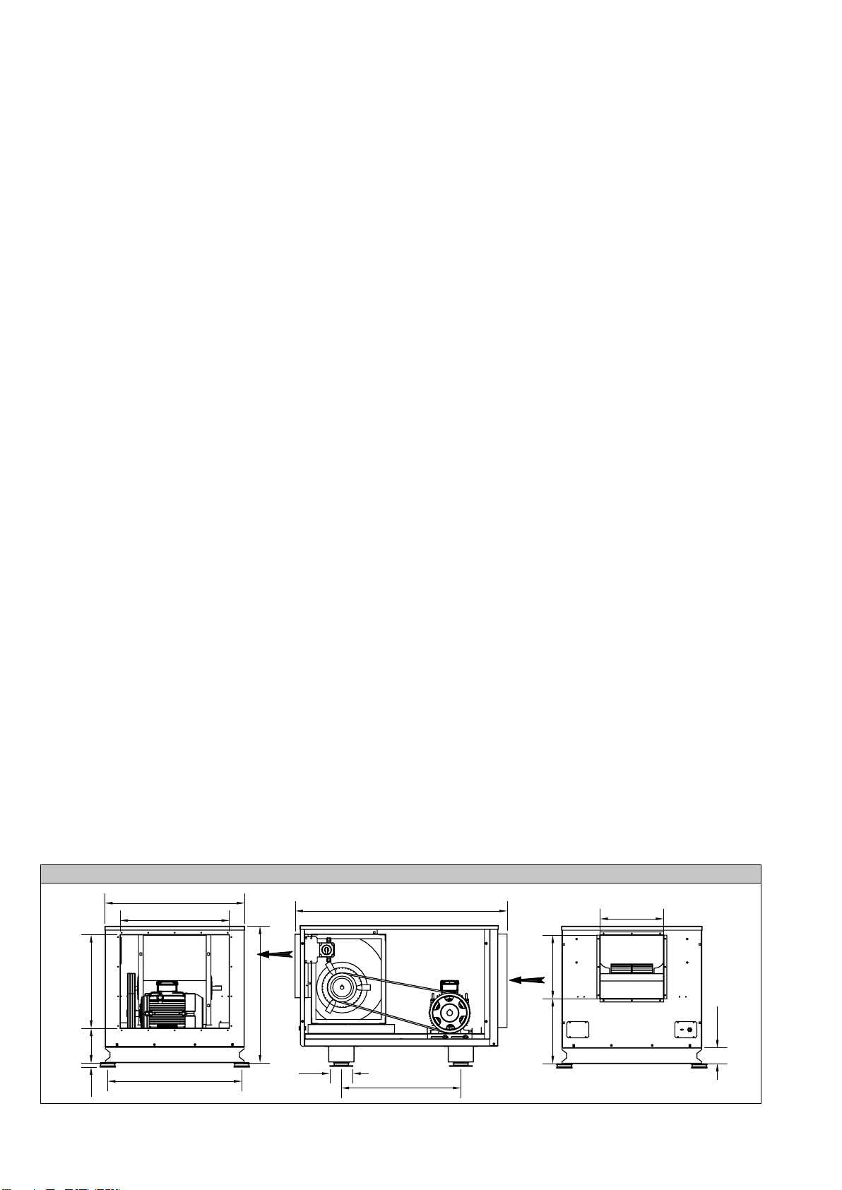
2. DESCRIPTION.................................................................................................................................... 3
3. INSTALLATION .................................................................................................................................. 4
3.1 Handling ................................................................................................................................... 4
3.2 Installation ................................................................................................................................ 4
3.3 Vertical installation.................................................................................................................... 5
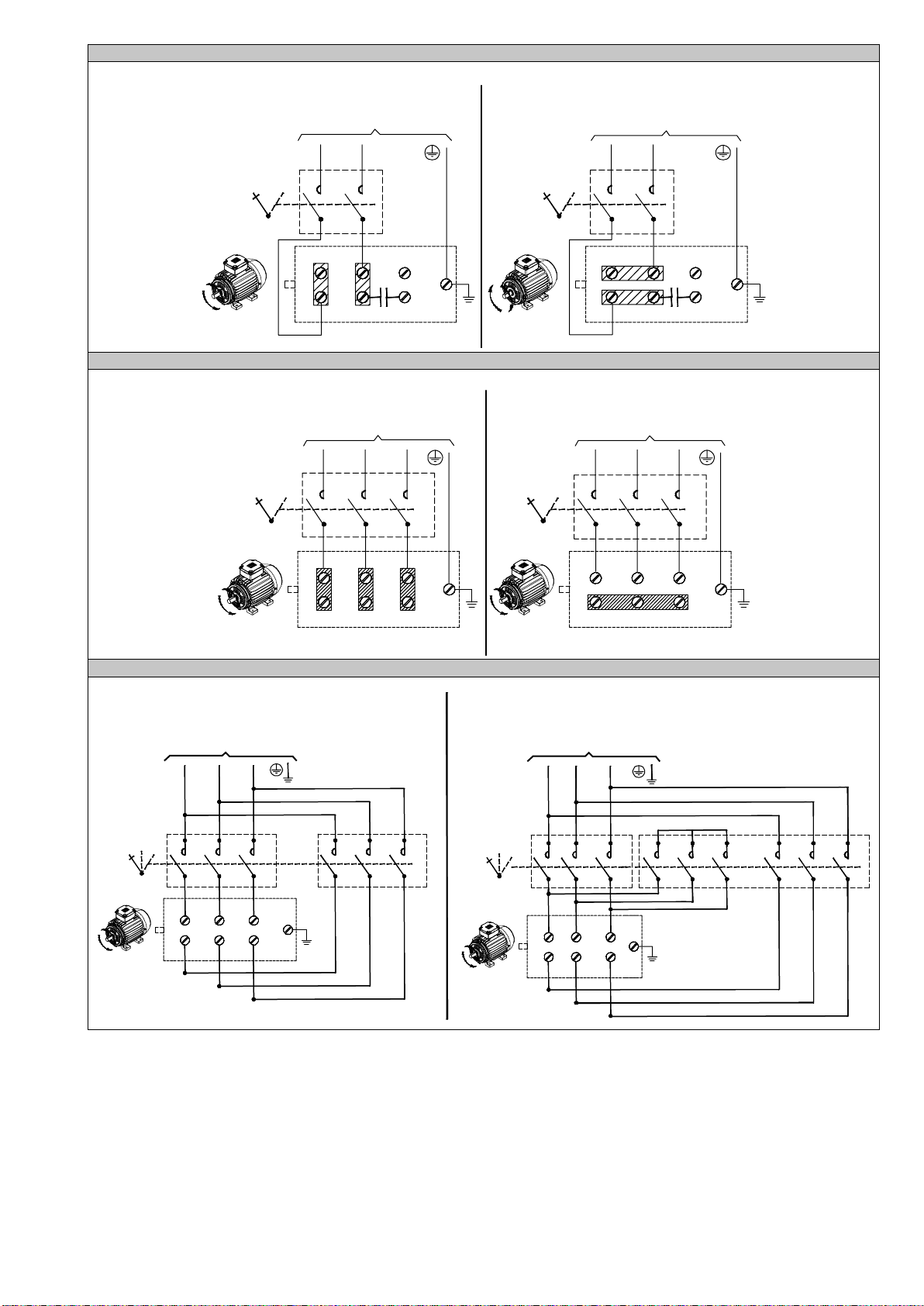
4. ELECTRICAL CONNECTION............................................................................................................ 5
5. COMMISSIONING.............................................................................................................................. 7
6. MAINTENANCE.................................................................................................................................. 8
7. WASTE MANAGEMENT.................................................................................................................... 8
7.1 Treatment of packaging and general industrial waste (GIW) ................................................... 8
7.2 Treatment of Professional WEEE............................................................................................. 8

3/8 NT00000602-KSHA-KSHR-AN-200605
Before starting, check the following points:
• Make sure that the device does not contain any foreign bodies.
• Check that all the components are mounted in their original positions.
• Check manually that the fans do not rub or get blocked.
• Check the connection of the earth electrode.
• Check that the access cover is properly closed.
N.B.: If the unit’s inlets or outlets are not connected, use an appropriate protective screen (AVRZ, PPHZ
or APC) Check the connection of the earth electrode. Electrical connection work must be carried out by
qualied personnel. Don’t forget to connect the earth electrode.
1.3 Reception - Storage
In case of short shipment, non-conformity, and/or total or partial damage to the products delivered, the
Buyer must, in accordance with article 133-3 of the French Commercial Code, add written reservations to
the carrier’s delivery slip and conrm them within 72 hours by registered letter with acknowledgement of
receipt with a duplicate for the seller. If the equipment is received without express reservation, the Buyer
has no subsequent recourse against us.
The product must be stored protected from weather, shocks and soiling due to splashing of any kind during
its transport from the supplier to the nal customer and on the site before installation.
1.4 Warranty
The equipment is covered by a parts-only warranty from the billing date.
The seller undertakes to replace all parts or equipment that we recognise as malfunctioning, to the exclu-
sion of any damages or penalties such as operating losses, market injury and other non-material or indirect
damage.
The following are excluded from our warranty: faults connected with abnormal use or use not in accord-
ance with the recommendations in our manuals and instructions, defects found following normal wear and
tear, incidents caused by negligence, failure to monitor or maintain correctly, defects due to poor installa-
tion of the equipment or to poor storage conditions before installation.
In any event, the seller is not responsible for equipment that has been modied or repaired even if only
partially.
2. DESCRIPTION
• KSHA: dynamically-balanced galvanised steel dual-eye action turbine
• KSHR: dynamically-balanced painted galvanised steel dual-eye reaction turbine
• One-piece galvanised steel sheet unit
• In-line (horizontal) or top (vertical) discharge
• Two omega cross-pieces guarantee overall stiness and mean slings can be used for lifting
• Removable side panels on both sides for easy access
• Transmission-motor set mounted inside the unit
Horizontal discharge
Q
M
B
C
Asp. G
Asp. F
Fix. D
AH
R
Fix. E
Ref. H
Ref. H
N
102

4/8 NT00000602-KSHA-KSHR-AN-200605
Vertical discharge
B
Q
M
C
CV
AV
P
Asp. F
Fix.D RFix.E
102
Ref.H
Ref.H
Asp. G
Size AH AV B C CV D E F G H M N P Q R
200 993 981 595 703 742 555 680 400 500 258 249 392 500 28 125
250 1,130 1,118 727 784 824 679 766 500 600 324 221 411 569 28 125
280 1,177 1,168 824 776 816 780 777 600 700 362 146 379 609.5 28 125
315 1,360 1,329 896 876 916 860 767 600 700 408 221 416 683.5 28 125
355 1,490 1,457 1,006 990 1,030 966 897 700 800 457 221 476 744 28 125
400 1,594 1,565 1,120 1,036 1,078 1,071 926 800 900 509 184 471 753 28 125
450 1,761 1,734 1,191 1,119 1,162 1,143 1,130 900 1,000 570 184 486 825 39 182
500 1,919 1,891 1,387 1,222 1,264 1,340 1,180 900 1,000 640 249 521 964 39 182
560 1,919 1,891 1,387 1,269 1,310 1,340 1,180 1,000 1,100 718 189 492 999 39 182
* anti-vibration supports delivered as an option (PAVZ)
3. INSTALLATION
3.1 Handling
KDTA-R Horizontal Nu
CaissonActionTransmission
Puissance
Intensité
Vitessederotation
Nameplate
Runtheslingsthrough
the cross-pieces
Unit characteristics: See nameplate on side of unit
3.2 Installation
Anti-vibration supports
(only fasten to ground)
Use of anti-vibration supports is recommended.
• Use with aeraulic network exible connectors is strongly recom-
mended to avoid transmission of vibrations
• Leave a minimum distance (L) of 60cm on the transmission side
for technical work

5/8 NT00000602-KSHA-KSHR-AN-200605
3.3 Vertical installation
KDTA-RHori zontalNu
CaissonActionTransmission
Puissance
Intensité
Vit es sederotation
Use wide
washers (LL type)
Flexible
connector
Only sizes 200 to 355 can be fastened vertically against a wall. Never
install anti-vibration supports in case of vertical fastening.
• Use with aeraulic network exible connectors is strongly recom-
mended to avoid transmission of vibrations.
• Leave a minimum distance of 60cm on the transmission side for
technical work
• Do not block the air vents on either side of the unit.
Vertical fastening against a wall for KSHA-KSHR 200 to 355:
Size Min. weight-bearing capacity of each fastening (Kg) Ø of fastening holes (mm)
200
118.5 11
250
149 11
280
172 11
315
206 13
355
296 13
4. ELECTRICAL CONNECTION
Electrical connection work must be carried out by qualied personnel. Electrical connection work must be
carried out according to the NF C15-100 standard, which requires the motor to be protected by an all-pole
device with an opening distance of 3mm per contact.
Don’t forget to connect the earth electrode.
In case of use for smoke extraction, please refer to the NF S 61-932 standard for connection and installa-
tion. Use CR1-C1 high-temperature cable. The cable MUST be protected against UV radiation.
In case of use in “comfort” mode, the motor must be protected by an appropriate thermal protection device.
Attention! Before carrying out any work, check that the power supply has been shut o.
N.B.: For each speed, the direction of rotation of the wheel must match the direction shown by
the arrow found on the product. A unit with a wheel that does not turn in the right direction stills
creates air ow and reduces pressure in the duct. Incorrect direction of rotation causes abnormal
motor heating, potentially even destruction, and cancels our manufacturer’s warranty.
Wiring without INTZ
Remove the unit side panel using a 13mm spanner. Connect the power cable directly to the motor’s ter-
minal box (cable glands are supplied). Start up the motor for a few seconds to test the direction of rotation
of the turbine. If the direction of rotation is incorrect, invert 2 phases (three-phase motor). N.B. in case of
a two-speed motor, check the direction of rotation of the turbine for both speeds. Shut the motor terminal
box and replace the unit side panel.

6/8 NT00000602-KSHA-KSHR-AN-200605
Single-phase motor
V2U2W2
U1 V1 W1
PE
NPh
0GV
V2U2
W2
U1 V1 W1
PE
NPh
0GV
Single-phase
1 speed motor
230 Vac 50Hz
Single-phase
1 speed motor
230 Vac 50Hz
Three-phase motor
U1V1
W1
V2 U2 W2
Motor D230/Y400V
PE U1V1
W1
V2 U2 W2
PE
L2 L3L1
0GV
L2 L3L1
0GV
Three-phase
1 speed motor
230 Vac 50Hz
Three-phase
1 speed motor
230 Vac 50Hz
Motor D230/Y400V
Independent winding or Dahlander motor
U1V1W1 PE
0GV
L1
Three-phase independent winding Y/Y
2 speed motor
400 Vac 50Hz
GVPV
PE
L1
GV
PV GV
PV 0GV
PV
L2 L3
U1V1W1
V2 U2 W2
V2 U2 W2
L2 L3
Three-phase Dahlander Y/YY
2 speed motor
400 Vac 50Hz
Wiring with mounted-wired INTZ
Remove the unit side panel using a 13mm spanner. Connect the power cable to the INTZ (cable glands
are supplied) according to the nameplate included on the unit. Start up the motor for a few seconds to test
the direction of rotation of the turbine. If the direction of rotation is incorrect, invert 2 phases (three-phase
motor). N.B. in case of a two-speed motor, check the direction of rotation of the turbine for both speeds.
Close the INTZ box and replace the unit side panel.

7/8 NT00000602-KSHA-KSHR-AN-200605
Wiring with PILOTAIR®
Connect the power cable in the PILOTAIR®according to the manual included with the relay cabinet (cable
glands supplied) Start up the motor for a few seconds to test the direction of rotation of the turbine. If the di-
rection of rotation is incorrect, invert 2 phases on the PILOTAIR®power supply terminal block (three-phase
motor). N.B.: in case of a Comfort-Smoke Extraction PILOTAIR®, please refer to the PILOTAIR®manual.
Pressure switch wiring
If the pressure switch is factory-installed, it is fastened to the inside of the unit on the motor side. Open the
unit side panel then the cowl located on the pressure switch. Connect the 2 connection cable wires. Set
the pressure switch trigger value. Close the pressure switch cowl then the unit side panel.
Variable speed pulley adjustment (optional)
Shut o the power supply before carrying out any work and make sure that it cannot be accidentally turned
back on.
• Unscrew the four locking screws on the side of the motor bracket
• Loosen the belt by unscrewing the tightening screw provided for this purpose
• Depending on the type of variable-speed pulley:
Unscrew the 4 hexagon-socket locking screws, ad-
just the mobile ange and screw the 4 screws back
in.
Unscrew the 2 hexagon-socket locking screws, ad-
just the mobile ange and screw the 2 screws back
in, making sure that they press against the bottom
of the 2 grooves, to avoid damaging the pulley’s
thread.
To reduce the rotation speed: unscrew the mobile ange screw
To increase the rotation speed: screw in the mobile ange screw
Attention! The fan’s rotation speed must never exceed the maximum speed of rotation specied
on the product nameplate.
5. COMMISSIONING
Before starting up the turbine, make sure that the fan, motor and transmission set rotates freely and that
no objects are liable to be launched by the turbine. The unit must be connected to the aeraulic network
and the side panels closed.
Briey turn on the power supply to check the turbine’s direction of rotation.
For each speed, the wheel’s direction of rotation must match the direction shown by the arrow
found on the product. If the wheel’s direction of rotation is incorrect, the motor is damaged and our
manufacturer’s warranty is cancelled.
All installation and maintenance work must be carried out with the wheel stopped and the device discon-
nected. During operation, check that the motor’s input current does not exceed the current specied on
the plate by more than 5%.

8/8 NT00000602-KSHA-KSHR-AN-200605
Once installation and testing are completed, present the main points of the user and maintenance manual
to the user. Depending on the control system set to be installed on the unit, it will be necessary to explain:
• How to turn the machine on and o.
• How to modify the operating modes.
Provide the user with the unit’s instruction manual and the user and maintenance manuals of the accesso-
ries installed (control, variable frequency drive, etc.) so they can be consulted at any time.
6. MAINTENANCE
Maintenance frequency depends on operating conditions. If the air has a high impurity content, the time
between two checks must be reduced. In general, the fan must be inspected at least twice a year.
Attention! Shut o the power supply before carrying out any work and make sure that it cannot be turned
back on during the work (lockout-tagout).
Fan: annual maintenance
Remove the dust on the fan blades. For the kitchen version, an inspection panel provides access to the
turbine.
Transmission: half-yearly maintenance
When using new belts, their tension must be checked and adjusted after 30 minutes of operation, if nec-
essary.
• Check the belt’s state of wear.
• Check the belt’s tension as follows:
-Apply force F as shown in the diagram, below, to achieve flex of f (mm) = 16xA (m)
-The force F to be applied varies according to the diameter of the smallest pulley and the type of belts
A
Ød
F
f
Belt type D (mm) F (Kg)
SPZ 67-95 1.0-1.5
100-140 1.5-2.0
SPA 90-132 1.8-2.7
140-200 2.8-3.5
7. WASTE MANAGEMENT
7.1 Treatment of packaging and general industrial waste (GIW)
The packaging (pallets not on deposit, cartons, lms, wooden boxes) and other GIW must be made reus-
able by an approved service provider.
It is strictly prohibited to burn, bury or dump them in the natural environment.
7.2 Treatment of Professional WEEE
This product must not be dumped or treated with household refuse, but must be dropped o at an appro-
priate collection point for waste electrical and electronic equipment (WEEE).
Non-binding document. With a view to continuously improving equipment, the manufacturer reserves the
right to make any technical modications without giving prior notice.
VIM
Les prés de Mégy Sud – SOUDAN
CS 60120 - 79401 ST MAIXENT L’ECOLE CEDEX
Tel.: 05 49 06 60 38 or 05 49 06 60 25 – Fax: 05 49 06 60 36
This manual suits for next models
1
Table of contents