Trane BAYECON203AA Assembly instructions

Model:
BAYECON203AA/AB
BAYECON204AA/AB
BAYRLAY006A
Horizontal Economizer & Rain Hood
Used with:
4WCZ6, 4YCZ6024-036, & 4DCZ6036
4WCZ6, 4YCZ6, & 4DCZ6048-060
(Required with 4WCZ6 & 4DCZ6 models)
General
The economizer is a multi-damper design. It inserts into the
return air stream and is connected to the unit low voltage
supply through wire leads. The economizer is fully accessible
through an access panel.
Use care when inserting the economizer in the return
air compartment, to prevent damaging the foil faced
insulation.
18-HE84D1-1B-EN
Installer’s Guide
ALL phases of this installation must comply with NATIONAL, STATE AND LOCAL CODES
WARNING:
HAZARDOUS VOLTAGE - DISCONNECT POWER BEFORE SERVICING
IMPORTANT: After the Economizer installation you must
install an air lter rack ordered separately. Use:
BAYFLTR101B for 4WCZ6, 4YCZ6024-036, 4DCZ6036
BAYFLTR201B for 4WCZ6, 4YCZ6, 4DCZ6048-060.
When the economizer is installed in 4WCZ6 & 4DCZ6
models, relay accessory kit BAYRLAY006A is required.
Refer to Figure 7 on page 7 to make your relay wiring
connections in the Control Box.
Inspect Contents
You must report damage and make claims to the transpor-
tation company immediately. Report missing parts to your
supplier immediately and replace with authorized parts
only.
Identify Economizer Kit Contents
Refer to Figure 2 on page 3 to identify the kit contents.
ELECTRIC SHOCK HAZARD
Open and lock out all unit disconnects prior to ac-
cessory installation or unit maintenance, to prevent
injury or death from electrical shock or contact with
moving parts.
SAFETY HAZARD
Do not remove end covers from Economizer actua-
tor; the spring-return assembly may release and
cause personal injury.
s
s
WARNING
ss
WARNING
CAUTION
IMPORTANT — This Document is customer property and
is to remain with this unit. Please return to service informa-
tion pack upon completion of work.
Install Economizer Kit
1. Remove Power
Disconnect and verify that power is o.
2. Remove Access Panels
Remove these three (3) access panels
(see Figure 1, page 3):
• Control/Heat access panel
• Blower access panel
• Coil access panel
3. BAYRLAY006A Installation (Required for
4WCZ6 & 4DCZ6 units only, 4YCZ6 units
skip to step 4)
1. Remove wire harness that came attached to the
BAYECON Logic Module being installed.
IMPORTANT: Do NOT remove the resistors from the
Logic Module. Also, Do NOT remove the YL & YL/BK
wires connected to SO and + on the Logic Module
2. Locate the ICMC Board in the upper left hand corner
of the unit control box and the DFC board in the upper
center of the unit control box. See Figure 5, page 5.
3. Using the existing holes in the back of the unit control
box, mount the relay bracket assembly using the 2
screws supplied with the BAYRLAY0006A Kit. See
Figure 5, page 5.
4. Route the BAYRLAY006A wire harness attached to
the relays to the logic module as shown in Figure 3 on
page 4.
5. Connect the BAYRLAY006A to the economizer Logic
Module and make the eld connections as shown in
Figure 7 on page 7.

2
INSTALLER’S GUIDE
Be certain to cap the ends of the cut YL/RD and YL wires that
are not being connected to an accessory or the unit to reduce
the risk of a short.
CAUTION
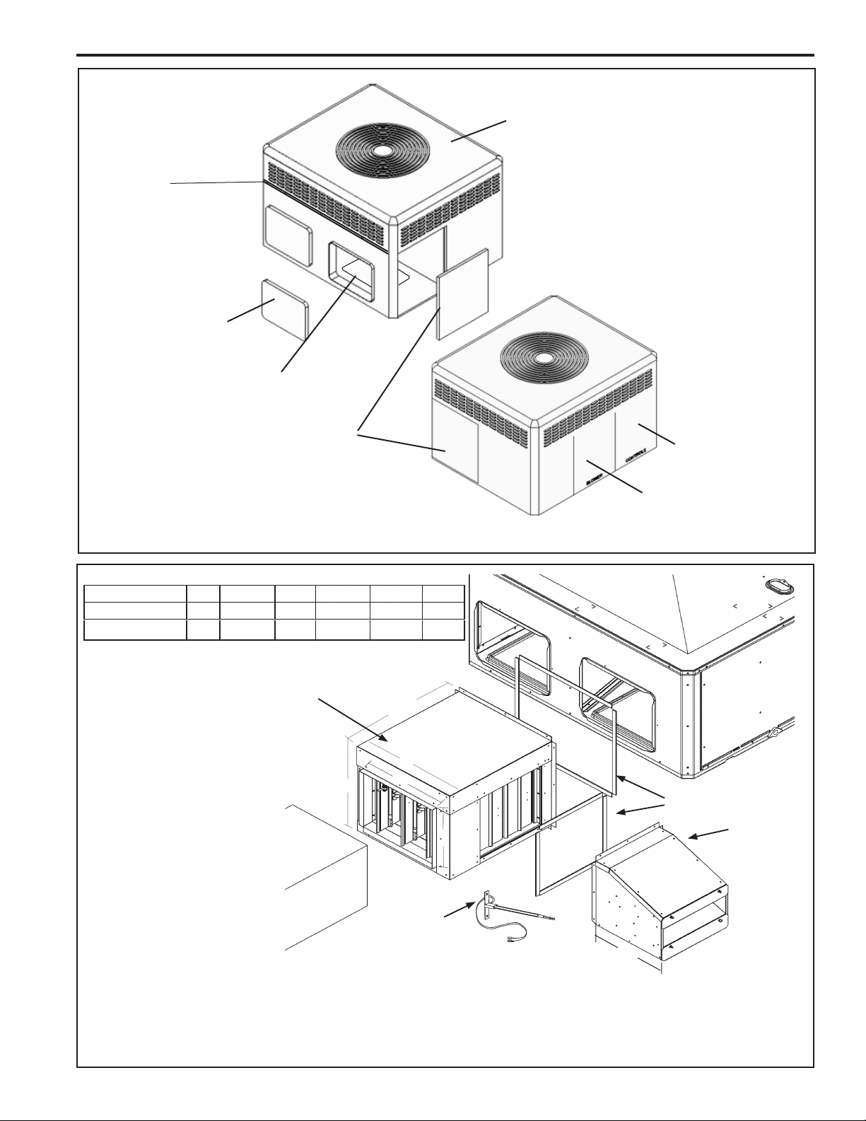
4. Install Economizer Assembly
1. Apply two gaskets to horizontal economizer mounting
anges. See Figure 2 on page 3.
2a. Small Cabinet - BAYECON203AA/AB
(4WCZ6, 4YCZ6024-036, 4DCZ6036)
Set the horizontal economizer over the horizontal return air
opening on the unit. The notches in the bottom ange of the
economizer clear the two existing screws below the return
air opening of the unit.
2b. Medium Cabinet - BAYECON204AA/AB
(4WCZ6, 4YCZ6, 4DCZ6048-060)
Apply a gasket to the economizer and slide the topange of
the economizer under the lip between the top and bottom
sections of the unit. Mate the notches on the top ange of
the economizer with the existing screws between the top and
bottom sections of the unit. The notches on the bottom ange
of the economizer clear the two existing screws below the
return air opening of the unit.
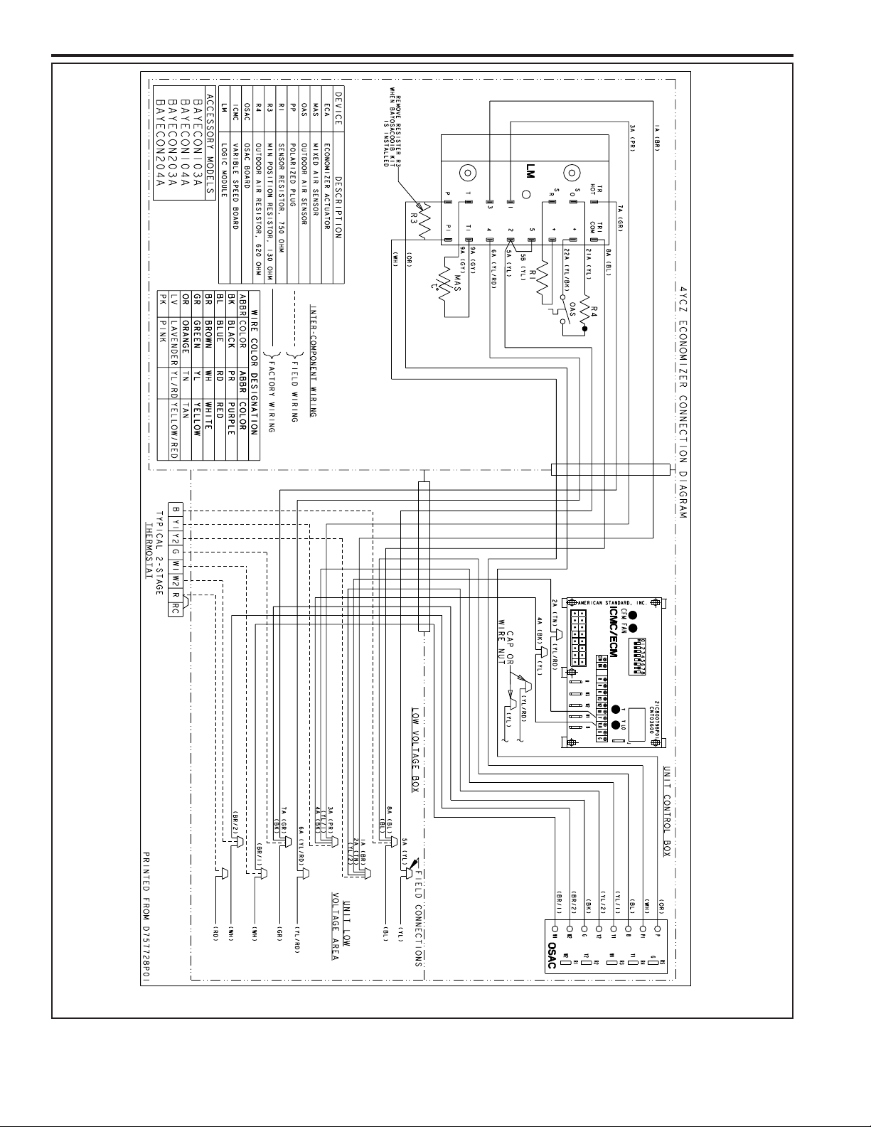
3. Drill three (3) 9/64” holes through the mating holes in the top
ange of economizer and into the unit. Then, drive three (3)
#10 sheet metal screws to secure the top.
4. Drill three (3) 9/64” engagement holes on each side of the
economizer. Then, drive three (3) #10 sheet metal screws
into each side of the economizer to the unit.
5. Mount the Mixed Air sensor to the left Blower partition
using two sheet metal screws. See Figure 4, page 4. The
Yellow and Yellow/Black wires will connect to the Econo-
mizer wiring harness in a later step. Install any economizer
options at this time per instructions provided with the sen-
sor.
6. Apply a gasket to the Rain Hood anges. See Figure 2, page
3.
7. Place the Rain Hood over the horizontal return air opening
of the economizer. See Figure 2, page 3. Use the #10 sheet
metal screws provided to attach the hood to the economizer.
8. Route the main wiring harness. From the Economizer as-
sembly, route the main wiring harness to the Mixed Air sensor
and to the Control Box. See Figure 3, page 4.
9. Connect the two (2) Mixed Air Sensor wires (pulled from har-
ness) to the mating pigtail wires (with female quick connects)
from the Mixed Air Sensor.
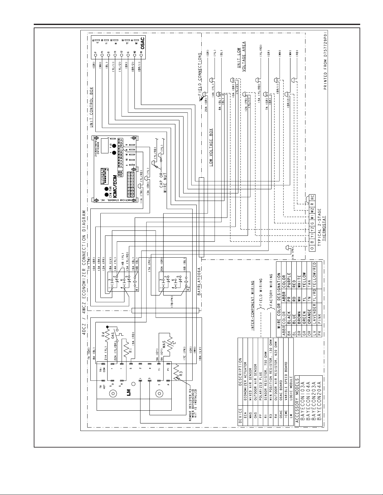
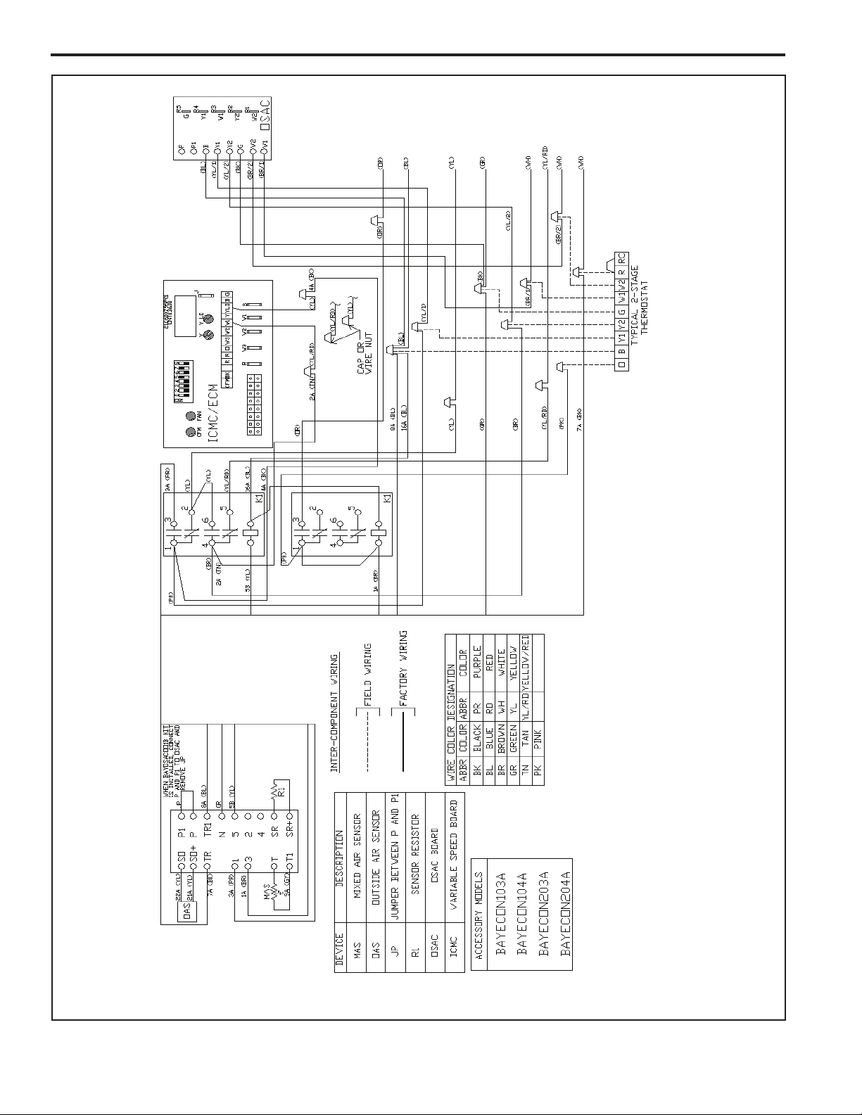
10. In the Control Box, locate the ICMC Board in the upper left
hand corner of the Control Box. Find the YL/RD and YL wires
in the 12 pin connector. Leaving enough length of these wires
so that the ends going to the ICMC Board can be stripped,
cut these wires in two. Strip the cut end of the wires going
to the ICMC Board and connect to economizer wires as per
hookup diagrams on pages 6 and 7. Cap the ends of the
Yellow and Yellow/Red wires not being hooked up. Secure
all wires with wire ties so that there is no interference with
any moving parts in the unit.
11. In the Control Box, complete the wiring connections per the
appropriate wiring diagram on pages 6 and 7. Secure all
wires so that there is no interference with any moving parts
in the unit.
12. Attach the return duct to the economizer.
13. Power the economizer and run the checkout procedure on
page 8. Make desired adjustments to the controller: set the
minimum occupied damper position, set the outside air (if
enthalpy used).
14. Replace the unit Coil access panel, the Blower access panel,
and the Control Box access panel.
Sequence Of Operation - Units Equipped With
Honeywell W7459 Logic
NOTE: A (G) signal is required for the economizer to operate.
As shipped, the economizer will not operate when there is a
signal for Heating Modes utilizing gas heat.
Fan Only (G): When the thermostat sends a signal for fan only
(G), the economizer will open to the minimum position setting
regardless of the outdoor air conditions and the indoor blower
will operate at approximately 50% airow.
Heating (W1), (W2), (Y1, Y2 on Heat Pump or Dual Fuel
Models): When the thermostat sends a signal for auxiliary heat
(G) +(W1) or rst stage heat (G) + (Y1,Y2), the economizer
will open to the minimum position setting. When the ambient
temperature may be below 70F, the economizer will not fully
open to the economizing position, when there is a signal for
heat. In order to receive fresh air and open the dampers to the
minimum position setting, you must provide a G signal to the
unit from the thermostat or comfort control being used.
FREE COOLING NOT AVAILABLE: When the outdoor air
conditions are not sucient for “Free Cooling” the Economizer
will open to the minimum position setting only and the unit will
function.
FREE COOLING AVAILABLE:
1st Stage Cooling (Y1) + (O for Heat Pumps and Dual Fuel
models): When outdoor air conditions are sucient for “Free
Cooling” and the thermostat sends a signal for 1st stage cooling
(G) + (Y1) + (O for Heat Pumps and Dual Fuel models), the
economizer will modulate accordingly and the indoor blower will
run at approximately 70% airow.
2nd Stage Cooling (Y1) + (Y2) + (O for Heat Pumps and
Dual Fuel models): When outdoor air conditions are sucient
for “Free Cooling” and the thermostat sends a signal for 2nd
stage cooling (G) + (Y1) + (Y2) + (O for Heat Pumps and Dual
Fuel models), the economizer will modulate accordingly, the
compressor will operate on low speed, and the indoor blower
will operate at 100% airow.
Unit “OFF” Mode
When the economizer is not receiving a 24V signal to the TR
terminal, or if power is disconnected to the unit, the dampers
will be fully closed to the outside air and fully open to the return
air.
NOTE: Free Cooling refers to the process of circulating
unconditioned outside air, without operating the compressor, to
cool the structure.

3
INSTALLER’S GUIDE
Figure 1. Remove Panels
4WCZ6, 4YCZ6, or 4DCZ6 Unit
Horizontal
Return Air
Panel
Down Flow
Return Air
Panel
Blower Access Panel
Control Box Ac-
cess Panel
Coil Access
Panel
Top Sealing
Flange
Economizer AB CD EF
BAYECON203AA/AB 22" 20" 16-7/8" 15-11/16" 11-11/16" 15"
BAYECON204AA/AB 26" 22-21/32" 19" 17-11/16" 14-11/16" 21-3/8"
Economizer & Logic Module
(Logic Module not shown
located inside economizer)
Mixed Air Sensor
Duct Rain Hood &
Mist Elimi-
nator
(Mist
Eliminator
not shown,
located
inside Rain
Hood)
Gaskets (2)
A
B
D
E
F
C
Figure 2. Horizontal Economizer Assembly & Kit Contents
NOTE: BAYECON204A economizer only contains two clearance notches in the top ange, BAYECON203A shown.

4
INSTALLER’S GUIDE
See View ‘A’
Mount the Mixed Air
Sensor to the partition
using two (2) sheetmetal
screws. See view A for
approximate positioning
View ‘A’ Approximate
Mounting Dimensions
2.82”
1.80”
Figure 4. Mount Mixed Air Sensor in Blower Compartment
Figure 3. Main Wire Harness Routing
Location of
Mixed Air Sensor
1.) From economizer
assembly, pass wire
harness through coil
Grommet. See View A.
2.) Continue routing
behind compressor
compartment and into
Blower Compartment.
Coil Grommet
3.) Pull the two (2) Mixed Air
Sensor wires (with female quick
connects) from the harness and
route down near the Mixed Air
Sensor. Connect to sensor
pigtail wire leads. 4.) Continue Routing the
Remaining Harness
Through the Grommet
and into the Control Box.
View A
Coil Grommet Location

5
INSTALLER’S GUIDE
Figure 5. Mount BAYRLAY006A
ICMC BoardRelays DFC

6
INSTALLER’S GUIDE
Figure 6. 4YCZ6 Economizer Connection Diagram
IMPORTANT — Retain this wiring diagram; please return this document to service information pack upon completion of work.
Wiring Diagram for Economizer Using a Honeywell W7459 Logic

7
INSTALLER’S GUIDE
Figure 7. 4WCZ6 & 4DCZ6 Economizer Connection Diagram
IMPORTANT — Retain this wiring diagram; please return this document to service information pack upon completion of work.
Wiring Diagram for Economizer Using a Honeywell W7459 Logic

8
INSTALLER’S GUIDE
Figure 8. 4WCZ6 & 4DCZ6 Economizer Connection Diagram
A
A
A
A
IMPORTANT-Retain this wiring diagram; please return this document to service information pack upon completion of work.
Wiring Diagram for Economizer Using a Honeywell W7212 Logic

9
INSTALLER’S GUIDE
Figure 9. 4YCZ6 Economizer Connection Diagram
A
A
A
A
IMPORTANT-Retain this wiring diagram; please return this document to service information pack upon completion of work.
Wiring Diagram for Economizer Using a Honeywell W7212 Logic

10
INSTALLER’S GUIDE
Operate the motor through its complete open-close
stroke. If necessary, release one of the previously tight-
ened linkage connections to prevent damage. Check
for proper operation, making sure that the linkage does
not bind and that the motor travels smoothly throughout
its fully open and closed position. Table 1 describes
how to drive the motor to the full open and full closed
positions (power connected). If there is excess length
of linkage rod, cut it to size. Make necessary minor
adjustments until desired operation is obtained, and
tighten all nuts and set screws.
5A. Checkout - For Units with a Honeywell W7459 Control, Only. See 5B for W7212
This motor checkout ensures that:
1. The motor operates the load.
2. The motor responds properly to the controller.
3 . T h e r e i s n o b i n d i n g o f t h e l i n k a g e o r m o t o r
stalling at any point of travel.
If motor does not operate properly, check for proper
voltage or mechanical binding in linkage or damper.
If questions arise regarding this product, contact
your distributor or representative.
MODEL DRIVE MOTOR OPEN DRIVE MOTOR CLOSED SPRING RETURN
M7415 Power to TR and TR1, jumper T and T1 Disconnect jumper at T or T1 and
disconnect P or P1, if connected
Disconnect power at TR and
TR1
Table 1. Motor Operation Checkout - W7459 Control Only
Figure 10. Single Enthalpy Changeover Set Point
Single enthalpy: The enthalpy change-
over set point is set to return the outdoor
air damper to minimum position when the
enthalpy rises above its set point. The
enthalpy set point scale markings, located
on W7459, are A,B,C,D; see table for the
corresponding control point. The factory-
installed R4 WHITE 620-ohm jumper must
be in place across terminals + and SR.
12 14 16 18 20 22 24 26 28 30 32 34 36 38 40 42 44 46
90
100
80
70
60
50
40
30
20
10
ENTHALPY—BTU PER POUND DRY AIR
85
(29)
90
(32)
95
(35)
100
(38)
105
(41)
110
(43)
35
(2)
35
(2)
40
(4)
40
(4)
105
(41)
110
(43
)
45
(7)
45
(7)
50
(10)
50
(10)
55
(13)
55
(13)
60
(16)
60
(16)
65
(18)
65
(18)
70
(21)
70
(21)
75
(24)
75
(24)
80
(27)
80
(27)
85
(29)
90
(32)
95
(35)
100
(38)
APPROXIMATE DRY BULB TEMPERATURE— F ( C)
A
A
B
B
C
C
D
D
M11681
RELATIVE HUMIDITY (%)
1
1
HIGH LIMIT CURVE FOR W7459D.
CONTROL
CURVE
CONTROL POINT
APPROX. F (C)
AT 50% RH
A73 (23)
B70 (21)
C67 (19)
D63 (17)

11
INSTALLER’S GUIDE
Table 2. Enthalpy Checkout Procedure - W7459 Control
Checkout Procedure Response
A1. Disconnect power at TR and TR1.
2. Disconnect jumper P to P1.
3. Jumper TR to 1.
4. Jumper T1 to T.
5. If connected, remove C7400 Solid State Enthalpy Sensor from ter-
minals S0 and +. Ensure factory-installed 620 ohm resistor is connect-
ed to terminals Sr and +.
6. Apply power (24Vac) to terminals TR and TR1
LED is off.
Motor is in closed position.
B1. Disconnect factory-installed 620 ohm resistor from terminals Sr and
+LED turns on, motor drives toward open.
C1. To simulate high and low enthalpy (single enthalpy sensor) re-
connect factory-installed 620 ohm resistor from terminals Sr and +.
Connect 1.2K ohm 4074EJM Checkout Resistor across terminals So
and +.
―
2. Turn enthalpy setpoint potentiometer to "A". LED turns on, indicating low enthalpy.
Motor drives toward open.
3. Turn enthalpy setpoint potentiometer to "D". LED turns off, indicating high enthalpy.
Motor drives toward closed.
4. Disconnect the 1.2K ohm checkout resistor ―
D1. To verify sensor operation, reconnect the + lead of the outdoor
enthalpy sensor to the + terminal of W7459. ―
2. Connect a DC multimeter between terminal So of the W7459A and
terminal S of the enthalpy sensor. See Fig. 11 (positive meter lead to
terminal S of the enthalpy sensor).
Multimeter indication is between 3 and 25 mA if
sensor is operating properly.
If multimeter indicates zero, the sensor may be
wired backward.
3. When using differential enthalpy, check the return air enthalpy
sensor by connecting a DC multimeter between terminal Sr of the
W7459A and terminal S of the return air enthalpy sensor. (positive
meter lead to terminal S of the enthalpy sensor).
Multimeter indication is between 3 and 25 mA if
sensor is operating properly.
If multimeter indicates zero, the sensor may be
wired backward.
1
1
2
2
M9097
ENTHALPY CHANGEOVER
SETPOINT
LED LIGHTS WHEN
OUTDOOR AIR IS SUITABLE
FOR FREE COOLING
INSERT DC MILLIAMMETER BETWEEN SOAND S FOR CHECKOUT
AND TROUBLESHOOTING.
JUMPER USED FOR SINGLE ENTHALPY CONTROL.
TR TR1
A
BC
D
SO
SR
+
+
+
C7400
620 OHM
JUMPER
DC
MILLIMETER
W7459
S
+
1
1
M9098B
ENTHALPY
CHANGEOVER
SETPOINT
MINIMUM
DAMPER
POSITION
SETTING
LED LIGHTS
WHEN OUTDOOR
AIR IS SUITABLE
FOR FREE COOLING
MINIMUM DAMPER POSITION ADJUSTMENT
IS PRESENT ONLY ON W7459A,D MODELS.
Location of Enthalpy Set Point,
Minimum Position and LED
Meter Location for Checkout
and Troubleshooting
MULTIMETER
MULTIMETER
Figure 11. Enthalpy LEDs and Checkout

12
INSTALLER’S GUIDE
Table 3. Temp vs. OHM Values for MAS (Mixed Air Sensor)
Temp FTemp C R(K OHMS) DC Volts
33.8 19.576 3.910
35.6 29.092 3.882
37.4 38.636 3.894
39.2 48.204 3.863
41.0 57.796 3.829
42.8 67.412 3.790
44.6 77.048 3.749
46.4 86.705 3.713
48.2 96.380 3.674
50.0 10 6.073 3.634
51.8 11 5.782 3.590
53.6 12 5.507 3.550
55.4 13 5.247 3.507
57.2 14 5.000 3.420
59.0 15 4.767 3.373
60.8 16 4.545 3.328
62.6 17 4.335 3.283
64.4 18 4.136 3.239
66.2 19 3.948 3.180
68.0 20 3.769 3.157
69.8 21 3.599 3.118
71.6 22 3.437 3.080
73.4 23 3.284 3.034
75.2 24 3.138 3.007
77.0 25 3.000 2.971
78.8 26 2.869 2.932
80.6 27 2.744 2.896
82.4 28 2.625 2.860
84.2 29 2.512 2.824
86.0 30 2.404 2.787
87.8 31 2.301 2.750
89.6 32 2.204 2.714
91.4 33 2.111 2.676
93.2 34 2.023 2.639
95.0 35 1.938 2.600
96.8 36 1.858 2.561
98.6 37 1.781 2.526
100.4 38 1.708 2.484
Temp vs. OHM for MAS (Mixed Air Sensor)

13
INSTALLER’S GUIDE
5B. CHECKOUT - For Units with a Honeywell W7212 Control, Only. See 5A for W7459
Fig. 12. Meter location for checkout
and troubleshooting (W7212 shown).
M20612
N1
P1
T1
N2V
2V
2V
B
A
SR
SO
AQ
C
D
Free
Cool
10V
EXH
DCV
EXH
Set
10V
DCV
Max
10V
DCV
Set
Min
Pos
Open
P
T
AQ1
SO+
SR+
1
2
DC VOLTMETER
620 OHM RESISTOR
W7212
+
S
+
C7400
1
2
INSERT DC VOLTMETER BETWEEN AQ AND AQ1 FOR
CHECKOUT AND TROUBLESHOOTING.
JUMPER USED FOR SINGLE ENTHALPY CONTROL.
Equipment Damage Hazard.
Excessive force can damage potentiometer controls.
Use a small screwdriver when adjusting enthalpy
changeover and minimum damper position controls.
CAUTION
Table 4. Checkout for W7212, W7213, W7214 Economizer Connected to Honeywell Actuator
Step Checkout Procedure Proper Response
1. CHECKOUT PREPARATION FOR ECONOMIZING ONLY
Disconnect power at TR and TR1
All LED are o; Exhaust Fan contacts are open
Disconnect devices at P and P1
Jumper P to P1 (defaults to on board MIN POS potentiometer).
Place 5.6K ohm resistor across T and T1 (Blue sleeve-provides
input to economizer that the MAT is between 50-55F).
Jumper TR to 1 (call for cooling from the thermostat).
W7212 only jumper TR to N (places economizer in occupied
mode).
If connected, remove C7400 Enthalpy Sensor from terminals SO
and +.
Connect 1.2K ohm, from 4074EJM Checkout Resistor kit, (purple
sleeve) across terminals SO and + (makes OA enthalpy high).
Place 620 ohm resistor (white sleeve) across SR and + (makes
return enthalpy lower than OA).
Set MIN POS and DCV MAX potentiometers fully CCW.
Turn DCV setpoint potentiometer mid position (this sets the DCV
ventilation at approximately 1000 ppm).
Turn exhaust potentiometer to mid position (motor will be ap-
proximately 50% open when the exhaust fan contacts make).
Set enthalpy potentiometer to D.
W7214 only Jumper TR to O.
Apply power (24 Vac) to terminals TR and TR1
CHECKOUT AND TROUBLESHOOTING
Checkout requires a 9V battery, 620 ohm, 1.2K ohm, 5.6K ohm,
and 6.8K ohm resistors. Use Table 4 and Fig. 12 for checkout.

14
INSTALLER’S GUIDE
Step Checkout Procedure Proper Response
2. DIFFERENTIAL ENTHALPY
Execute stop one, Checkout Preparation. ―
Turn DCV MAX to mid position.
Place 620 ohm resistor across SOand + (white sleeve
resistor makes OA enthalpy low).
Place 1.2K ohm resistor across SRand + (purple sleeve resistor
makes RA enthalpy high).
Free cool LED turn on; motor drives to approxi-
mately 45 degrees (half) open.
Remove 620 ohm resistor from SOand +. Free cool LED turn o; motor drives closed
3. SINGLE ENTHALPY
Execute stop one, Checkout Preparation. ―
Turn DCV MAX to mid position.
Set enthalpy potentiometer to A (fully CCW). Free cool LED turns on; motor drives to approxi-
mately 45 degrees (half) open.
Set enthalpy potentiometer to D or E for W7212C (fully CW). Free cool LED turns o; motor drives closed.
4. DCV AND EXHAUST
Execute step one, Checkout Preparation. ―
LED for both DCV and Exhaust should be o.
Turn DCV MAX to mid position. Motor drives to mid position, 45 degrees open.
Turn MIN POS fully CW. Motor drives fully open.
Turn MIN POS and DCV MAX to fully CCW. Motor drives closed.
Turn DCV MAX to mid position.
Connect 9V battery positive to AQ and negative to AQ1.
LED for both DCV and Exhaust turn on.
Actuator drives to 45 degrees open.
Remove jumper from N terminal (economizer goes into not oc-
cupied mode). Motor remains at 45 degrees open.
Adjust DCV MAX towards CW. Motor will move to position set by DCV MAX pot.
Adjust DCV MAX to fully CCW. Motor will drive closed.
Reconnect jumper to N terminal.
Adjust DCV MAX and MIN POS pots. Motor will drive to the most open position of the
pots.
Adjust DCV MAX and MIN POS pots to fully CCW.
Remove power from N terminal adjust MIN POS towards CW. Motor should not move.
Adjust DCV MAX towards CW. Motor will move to position set by DCV MAX pot.
5. MINIMUM AND MAXIMUM POSITION
Execute stop one, Checkout Preparation. ―
Connect 9V battery positive to AQ and negative to AQ1. Adjust
DCV MAX potentiometer to mid position.
DCV LED turns on. Actuator drives to 45 de-
grees open.
Turn DCV maximum position potentiometer to fully CCW. Actuator drives fully closed.
Turn minimum position potentiometer to midpoint. Actuator drives to 45 degrees open.
Turn minimum position potentiometer fully CW. Actuator drives fully open.
Turn MIN POS to fully CCW. Actuator drives fully closed.
W7212: Remove jumper from TR and N. Actuator drives fully closed.
W7214: Jumper TR to O.
6. MIXED AIR INPUT
Execute stop one, Checkout Preparation. ―
Turn DCV MAX to mid position; set enthalpy potentiometer to A. Free cool LED turns on.
Actuator drives to 45 degrees open.
Remove 5.6K ohm resistor (green sleeve) and place jumper from
T and T1. Actuator drives to 45 degrees open.
Remove jumper from T and T1 and leave open. Actuator drives fully closed.
Table 4. Checkout for W7212, W7213, W7214 Economizer Connected to Honeywell Actuator (Cont.)

About Trane and American Standard Heating and Air Conditioning
Trane and American Standard create comfortable, energy efficient indoor environments for residential applications.
For more information, please visit www.trane.com or www.americanstandardair.com
The manufacturer has a policy of continuous data improvement and it reserves the right to change design and specifications without notice.We are
committed to using environmentally conscious print practices.
© 2020
18-HE84D1-1B-EN 09 Jul 2020
Supersedes 18-HE84D1-1A-EN (May 2017)
This manual suits for next models
4
Table of contents
Other Trane Air Conditioner Accessories manuals

Trane
Trane KIT09667 User manual

Trane
Trane TR-OHS RCU Series Installation and operating instructions

Trane
Trane BAYCOVR112A Assembly instructions

Trane
Trane BAYECON103AA Assembly instructions

Trane
Trane BAYCOVR112 Assembly instructions

Trane
Trane BAYECON104AA Assembly instructions

Trane
Trane AFDR User manual

Trane
Trane BAYQSTK300B Assembly instructions

Trane
Trane BAYLOAMM003A Assembly instructions

Trane
Trane OxBox MAYKSKT001 User manual