manuals.online logo
Brands
  1. Home
  2. •
  3. Brands
  4. •
  5. Lennox
  6. •
  7. Air Handler
  8. •
  9. Lennox LDT Series Owner's manual

Lennox LDT Series Owner's manual

Other manuals for LDT Series

1

This manual suits for next models

5

Other Lennox Air Handler manuals

Lennox 16B27 Instruction Manual

Lennox

Lennox 16B27 Instruction Manual

Lennox CB19-21 User manual

Lennox

Lennox CB19-21 User manual

Lennox BCE3M E Series User manual

Lennox

Lennox BCE3M E Series User manual

Lennox CB26UH series User manual

Lennox

Lennox CB26UH series User manual

Lennox LCH092H Installation and operation manual

Lennox

Lennox LCH092H Installation and operation manual

Lennox CBA25UHE Series Installation and operation manual

Lennox

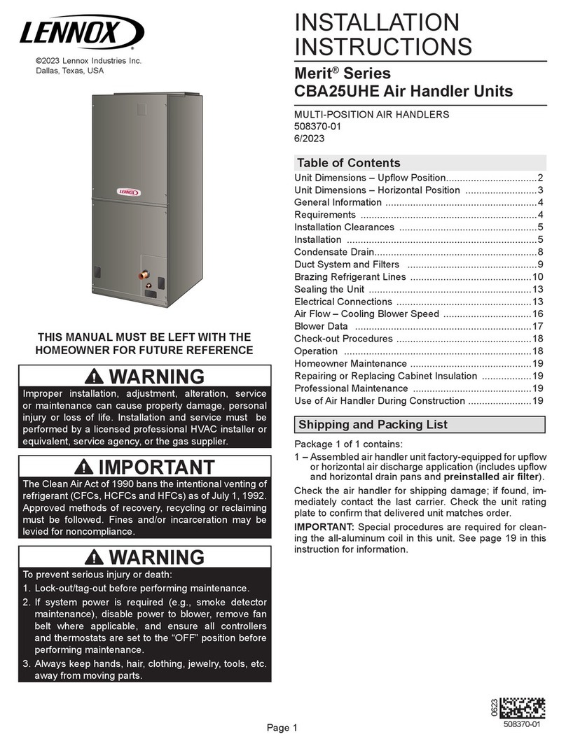
Lennox CBA25UHE Series Installation and operation manual

Lennox Signature CB31MV User manual

Lennox

Lennox Signature CB31MV User manual

Lennox Elite series User manual

Lennox

Lennox Elite series User manual

Lennox Elite CB30U Series User manual

Lennox

Lennox Elite CB30U Series User manual

Lennox CBX27UH User manual

Lennox

Lennox CBX27UH User manual

Lennox eNeRGy Series User manual

Lennox

Lennox eNeRGy Series User manual
Lennox CBA25UHV Series User manual

Lennox

Lennox CBA25UHV Series User manual

Lennox CB26UH series User manual

Lennox

Lennox CB26UH series User manual

Lennox CBX25UH Series User manual

Lennox

Lennox CBX25UH Series User manual

Lennox CBX32MV Series User manual

Lennox

Lennox CBX32MV Series User manual
Lennox DAVE LENNOX SIGNATURE CBX32MV User manual

Lennox

Lennox DAVE LENNOX SIGNATURE CBX32MV User manual

Lennox LIAH024-200U432-STDESP User manual

Lennox

Lennox LIAH024-200U432-STDESP User manual

Lennox 13ACC Series User manual

Lennox

Lennox 13ACC Series User manual

Lennox INALTO Installation and operating instructions

Lennox

Lennox INALTO Installation and operating instructions

Lennox MINIAIR User manual

Lennox

Lennox MINIAIR User manual

Lennox ELA Series Installation and operation manual

Lennox

Lennox ELA Series Installation and operation manual

Lennox VRF VEAH024C432P User manual

Lennox

Lennox VRF VEAH024C432P User manual

Lennox LGT Series Installation and operation manual

Lennox

Lennox LGT Series Installation and operation manual

Lennox DOAS DLV User manual

Lennox

Lennox DOAS DLV User manual
Popular Air Handler manuals by other brands

Vents VUT 270 V5B EC A14 user manual

Vents

Vents VUT 270 V5B EC A14 user manual

Armstrong Air BCE7S Series installation instructions

Armstrong Air

Armstrong Air BCE7S Series installation instructions

Klimor EVO-S Operation and maintenance manual

Klimor

Klimor EVO-S Operation and maintenance manual

Salda SMARTY XP MOUNTING AND INSTALLATION INSTRUCTION

Salda

Salda SMARTY XP MOUNTING AND INSTALLATION INSTRUCTION

BLAUBERG KOMFORT Roto EC S400 user manual

BLAUBERG

BLAUBERG KOMFORT Roto EC S400 user manual

Trenton TPLP Series installation instructions

Trenton

Trenton TPLP Series installation instructions

Daikin DV PTC 14 Series installation instructions

Daikin

Daikin DV PTC 14 Series installation instructions

Haier HB2400VA1M20 Installation & operation manual

Haier

Haier HB2400VA1M20 Installation & operation manual

Webasto BlueCool A-Series operating instructions

Webasto

Webasto BlueCool A-Series operating instructions

RDZ DA 701 Technical installation manual

RDZ

RDZ DA 701 Technical installation manual

Carrier 39T Installation, Start-Up and Service Instructions

Carrier

Carrier 39T Installation, Start-Up and Service Instructions

Armstrong Air BCE5V Series installation instructions

Armstrong Air

Armstrong Air BCE5V Series installation instructions

Carrier 40MBDAQ Service manual

Carrier

Carrier 40MBDAQ Service manual

TemperZone Econex Pro OPA 1410RLTM4FPQD Installation & maintenance

TemperZone

TemperZone Econex Pro OPA 1410RLTM4FPQD Installation & maintenance

RDZ WHR 200 Technical installation manual

RDZ

RDZ WHR 200 Technical installation manual

AAON H3 Series Installation operation & maintenance

AAON

AAON H3 Series Installation operation & maintenance

Kemper CleanAirTower operating manual

Kemper

Kemper CleanAirTower operating manual

Salda RIRS 400VE EKO 3.0 Technical manual

Salda

Salda RIRS 400VE EKO 3.0 Technical manual

manuals.online logo
manuals.online logoBrands
  • About & Mission
  • Contact us
  • Privacy Policy
  • Terms and Conditions

Copyright 2025 Manuals.Online. All Rights Reserved.

Page 1
LDT
Service Literature 6.5 / 7.5 / 8.5 /10 / 12.5
100086
LDT DUAL FUEL SERIES
WARNING
To prevent serious injury or death:
1- Lock-out/tag-out before performing maintenance.
2- If system power is required (e.g., smoke detector main
tenance), disable power to blower, remove fan belt
where applicable, and ensure all controllers and ther
mostats are set to the “OFF” position before
performing maintenance.
3- Always keep hands, hair, clothing, jewelry, tools, etc.,
away from moving parts.
The LDT commercial combination heat pump and gas heat
unit is available in 6.5 / 7.5 / 8.5 / 10 / 12.5 ton cooling ca
pacities. The LDT078, 092, 102, 122 and 150 refrigerant
systems utilize two compressors, two reversing valves, two
accumulators (122, 150 only), and other parts common to a
heat pump. Units are available in 130,000, 180,000 or
240,000Btuh (38.1, 52.7 or 70.3 kW) heating inputs. Gas
heat sections are designed with stainless steel tube heat
exchangers.
LDT078-150 units are equipped with variable-volume, di
rect drive blowers. These units will provide supply air at
lower speeds when cooling demand is low and increase to
higher speeds when cooling demand is high. Refer to Sup
ply Air Start-Up sections.
LDT units are designed to accept any of several different
energy management thermostat control systems with mini
mum field wiring.
Information contained in this manual is intended for use by
qualified service technicians only. All specifications are
subject to change. Procedures outlined in this manual are
presented as a recommendation only and do not super
sede or replace local or state codes.
If the unit must be lifted for service, rig unit by attaching four
cables to the holes located in the unit base rail (two holes at
each corner). Refer to the installation instructions for the
proper rigging technique.
WARNING
Improper installation, adjustment, alteration, service
or maintenance can cause property damage, person
al injury or loss of life. Installation and service must
be performed by a licensed professional HVAC in
staller or equivalent, service agency, or the gas sup
plier
CAUTION
As with any mechanical equipment, contact with
sharp sheet metal edges can result in personal in
jury. Take care while handling this equipment and
wear gloves and protective clothing.
WARNING
Electric shock hazard. Can cause injury
or death. Before attempting to perform
any service or maintenance, turn the
electrical power to unit OFF at discon
nect switch(es). Unit may have multiple
power supplies.
Table of Contents
Options / Accessories 2..........................
Specifications 5.................................
High Altitude 7..................................
Blower Data 8..................................
Electrical Data 11................................
I Unit Components 14............................
II Placement and Installation 28....................
III Start Up 28...................................
IV System Service Checks 31.....................
V Maintenance 34................................
VI Accessories 35................................
VII Wiring Diagrams 40...........................
Page 2
OPTIONS / ACCESSORIES
Item Description Catalog
Number
Unit Model No
078 092 102 122 150
COOLING SYSTEM
Condensate Drain Trap PVC 22H54 XXXXX
Copper 76W27 XXXXX
 21Z07 OX OX OX OX OX
GAS HEATING SYSTEM
Bottom Gas Piping Kit 54W95 XXXXX
Combustion Air Intake Extensions 19W51 XXXXX
Gas Heat Input   OOOOO
  OOOOO
  OOOO
  22A51 XXXXX
460V 22A55 XXXXX
575V 13X65 XXXXX
LPG/Propane Conversion Kits  14N22 XXXXX
Medium Heat 14N23 XXXXX
 14N25 XXXXX
 42W16 XXXXX
BLOWER - SUPPLY AIR
 ® OOOOO
CABINET
 24C86 OX OX OX
24C87 OX OX
  OOOOO
 51W25 XXXXX
 54W96 OX OX OX OX OX
CONTROLS
 21Z10 OX OX OX OX OX
 CPC Einstein Integration  OOOOO
® 54W27 OX OX OX OX OX
Novar®   OOOOO
 53W67 OX OX OX OX OX
 21Z08 OX OX OX OX OX
 11K76 OX OX OX OX OX
 11K80 OX OX OX OX OX




Page 3
OPTIONS / ACCESSORIES
Item Description Catalog
Number
Unit Model No
078 092 102 122 150
INDOOR AIR QUALITY
Air Filters
®󰀩

MERV 8 50W61 OX OX OX OX OX
MERV 13 52W41 OX OX OX OX OX
MERV 16 21U41 XXXXX
 Y3063 XXXXX
Indoor Air Quality (CO) Sensors
󰀨 77N39 XXXXX
󰀨 23V86 XXXXX
 87N52 XXXXX
 87N54 XXXXX
CO 85L43 XXXXX
77N3990N43 XXXXX
Needlepoint Bipolar Ionization (NPBI)
 22U15 XXXXX
UVC Germicidal Lamps
1® 21A93 XXXXX
  10H20 XXXXX
 10H21 XXXXX
ELECTRICAL
   OOOOO
  OOOOO
  OOOOO
 80 amp 54W56 OX OX OX OX OX
150 amp 54W57 OX OX OX OX OX
  OOOOO


 74M70 OX OX OX OX OX
  OOOOO
 67E01 XXXXX
³   OOOOO
 10C89 XXXXX
1

2
3




Page 4
OPTIONS / ACCESSORIES
Item Description Catalog
Number
Unit Model No
078 092 102 122 150
ECONOMIZER





20U80 OX OX OX OX OX
Horizontal Barometric Relief Dampers
 53K04 XXXXX
Economizer Controls
󰀨 Order 2 21Z09 OX OX OX OX OX
   OOOOO
 21Z09 OX OX OX OX OX
 13J77 XXXXX
 13J76 XXXXX
   OOOOO
OUTDOOR AIR
Outdoor Air Dampers With Outdoor Air Hood
Motorized 14G28 OX OX OX OX OX
 14G29 XXXXX
POWER EXHAUST
  53W44 OX OX OX OX OX
 53W45 OX OX OX OX OX
 53W46 OX OX OX OX OX
ROOF CURBS

 11F54 XXXXX
 11F55 XXXXX
 11F56 XXXXX
 11F57 XXXXX
Adjustable Pitch Curb
 54W50 XXXXX
CEILING DIFFUSERS
  13K61 X X
 13K62 XXX
  13K56 X X
 13K57 XXX
 C1DIFF30B-1 12X65 X X
C1DIFF31B-1 12X66 XXX




Page 5
SPECIFICATIONS 6.5 TON | 7.5 TON | 8.5 TON
General Data Nominal Tonnage 6.5 Ton 7.5 Ton 8.5 Ton
󰀩 High High High
Model Number LDT078H4E LDT092H4E LDT102H4E
Blower Type DirectPlus™
ECM Direct Drive
with MSAV®
DirectPlus™
ECM Direct Drive
with MSAV®
DirectPlus™
ECM Direct Drive
with MSAV®
Cooling
Performance
 79,000 92,000 100,000
1 78,000 90,000 98,000
 2400 2800 2800
   
1   
1   
 R410A R410A R410A


   
   
Heating
Performance
1 73,000 84,000 94,000
 2600 3000 3400
   
1   
1 40,000 46,000 53,000
   
1   
Gas Heating Options Available 




Compressor Type (number) 

Outdoor Coil    
 3/8 3/8 3/8
 333
 20 20 20
Outdoor
Coil Fans
      
Motor rpm 530-950 530-950 650-1010
 140-620 140-620 220-700
      
 333
 3600-7000 3600-7000 4600-7500
Indoor
Coil
   
 3/8 3/8 3/8
 444
 14 14 14
  
 

Indoor
Blower
   
      
Filters  
  
Electrical characteristics 

1
Cooling Ratings
High Temperature Heating Ratings
Low Temperature Heating Ratings
Page 6
SPECIFICATIONS 10 TON | 12.5 TON
General Data Nominal Tonnage 10 Ton 12.5 Ton
󰀩 High High
Model Number LDT122H4E LDT150H4E
Blower Type DirectPlus™
ECM Direct Drive
with MSAV®
DirectPlus™
ECM Direct Drive
with MSAV®
Cooling
Performance
 121,000 141,000
1 118,000 136,000
 3400 4200
  
1  
1  
 R410A R410A


  
  
Heating
Performance
1 114,000 128,000
 3600 4200
  11
1  
1 65,000 73,000
  
1  
Gas Heating Options Available 
Compressor Type (number) 

Outdoor Coil   
 3/8 3/8
 3 3
 20 20
Outdoor
Coil Fans
    
Motor rpm 530-950 530-950
 180-800 180-800
    
 3 3
 5500-10,600 5500-10,600
Indoor
Coil
  
 3/8 3/8
 4 4
 14 14
  
 

Indoor
Blower
  
    
Filters  
  
Electrical characteristics 

1
Cooling Ratings
High Temperature Heating Ratings
Low Temperature Heating Ratings
Page 7
SPECIFICATIONS GAS HEAT
Heat Input Type Standard Medium High
Number of Gas Heat Stages 2 2 2
Gas Heating

  84,500 117,000 156,000
 130,000 180,000 240,000
  104,000 144,000 194,000
Temperature Rise Range - °F 15 - 45 30 - 60 40 - 70
 2150 2250 2600
󰀩 80% 80% 81%
   
 
  
 
HIGH ALTITUDE DERATE
NOTE - Units may be installed at altitudes up to 2000 feet above sea level without any modications.
At altitudes above 2000 feet units must be derated to match gas manifold pressures shown in table below.
At altitudes above 4500 feet unit must be derated 2% (130K through 180K) and 4% (240K) for each 1000 feet
above sea level.
NOTE - This is the only permissible derate for these units.
Refer to the Installation Instructions for more detailed information.
Heat Input Type Altitude Feet
Gas Manifold Pressure
in. w.g. Input Rate (Btuh)
Natural Gas LPG/ Propane
 2001 - 4500   84,500 / 125,000
 2001 - 4500   117,000 / 173,000
 2001 - 4500   156,000 / 221,000
Page 8
BLOWER DATA
BLOWER TABLE INCLUDES RESISTANCE FOR BASE UNIT ONLY (NO HEAT SECTION) WITH DRY INDOOR COIL AND AIR
FILTERS IN PLACE.



󰀨

Maximum Static Pressure With Gas Heat - 2.0 in. w.g.
󰀨

Total
Air Volume
cfm
Total Static Pressure - in. w.g.
0.2 0.4 0.6 0.8 1.0 1.2 1.4
RPM Watts RPM Watts RPM Watts RPM Watts RPM Watts RPM Watts RPM Watts
1750 759 223 864 298 961 359 1049 420 1128 508 1199 607 1260 704
2000 846 271 943 345 1035 410 1117 488 1189 598 1255 704 1313 804
2250 945 303 1030 391 1111 476 1184 577 1247 697 1310 806 1367 905
2500 1035 366 1109 476 1180 583 1245 688 1306 797 1368 903 1426 1008
2750 1113 476 1182 601 1248 715 1310 809 1371 902 1432 1011 1491 1129
3000 1195 596 1261 718 1324 827 1385 922 1444 1024 1503 1146 1559 1279
3250 1282 711 1346 827 1406 935 1464 1044 1521 1167 1576 1306 1629 1460
3500 1372 821 1432 940 1489 1060 1544 1192 1598 1337 1650 1494 1700 1663
3750 1461 949 1517 1081 1571 1221 1624 1373 1675 1532 1725 1700 1773 1875
4000 1549 1109 1602 1256 1653 1413 1703 1576 1753 1743 1801 1916 1847 2091
4250 1637 1298 1687 1458 1735 1625 1784 1795 1831 1966 1877 2139 1923 2310
4500 1724 1510 1772 1678 1818 1851 1864 2023 1910 2195 1955 2365 2000 2530
4750 1811 1738 1856 1910 1901 2083 1946 2254 1990 2423 2034 2587 2079 2746
5000 1897 1973 1941 2144 1985 2314 2028 2480 2071 2644 2114 2805 2158 2959
5250 1983 2205 2026 2373 2069 2538 2111 2699 2153 2860 2195 3017 - - - - - -
5500 2070 2428 2112 2595 2153 2756 2194 2912 - - - - - - - - - - - - - - - - - -
5750 2156 2643 2197 2809 - - - - - - - - - - - - - - - - - - - - - - - - - - - - - -
Total
Air Volume
cfm
Total Static Pressure - in. w.g.
1.6 1.8 2.0 2.2 2.4 2.6
RPM Watts RPM Watts RPM Watts RPM Watts RPM Watts RPM Watts
1750 1316 793 1373 875 1432 963 1491 1064 1548 1175 1604 1300
2000 1368 894 1425 982 1483 1081 1540 1196 1596 1322 1650 1458
2250 1423 1001 1480 1101 1537 1216 1593 1344 1647 1483 1700 1629
2500 1483 1117 1539 1236 1594 1368 1648 1509 1700 1657 1752 1810
2750 1547 1256 1601 1394 1654 1539 1705 1690 1756 1846 1806 2004
3000 1612 1425 1664 1577 1715 1734 1765 1893 1815 2053 1864 2213
3250 1680 1623 1729 1787 1778 1949 1828 2110 1876 2269 1925 2426
3500 1748 1835 1796 2003 1844 2165 1893 2324 1942 2479 1991 2633
3750 1819 2048 1866 2214 1914 2374 1963 2530 2012 2684 2061 2837
4000 1893 2260 1940 2423 1988 2581 2036 2737 2084 2891 2134 3044
4250 1969 2475 2016 2634 2063 2790 2111 2945 2159 3098 - - - - - -
4500 2046 2689 2093 2844 2140 2998 2187 3153 - - - - - - - - - - - -
4750 2124 2900 2170 3053 - - - - - - - - - - - - - - - - - - - - - - - -
5000 2203 3111 - - - - - - - - - - - - - - - - - - - - - - - - - - - - - -
5250 - - - - - - - - - - - - - - - - - - - - - - - - - - - - - - - - - - - -
5500 - - - - - - - - - - - - - - - - - - - - - - - - - - - - - - - - - - - -
Page 9
BLOWER DATA
POWER EXHAUST FAN PERFORMANCE
Return Air System Static Pressure Air Volume Exhausted
in. w.g. cfm
0 3175
 2955
 2685
 2410
 2165
 1920
 1420
 1200
FACTORY INSTALLED OPTIONS/FIELD INSTALLED ACCESSORY AIR RESISTANCE - in. w.g.
Air
Volume
cfm
Wet Indoor Coil Gas Heat Exchanger
Economizer
Filters Return
Air
Adaptor
Plate
092, 102 122 Standard
Heat
Medium
Heat
High
Heat MERV 8 MERV 13 MERV 16
1750          
2000          
2250          
2500          
2750          
3000          
3250          
3500          
3750          
4000          
4250          
4500          
4750          
5000          
5250          
5500          
5750          
6000          
Page 10
BLOWER DATA
CEILING DIFFUSERS AIR RESISTANCE - in. w.g.
󰀨 FD11 Flush
󰀨
Unit Size Air Volume
cfm 2 Ends Open 1 Side, 2 Ends
Open
All Ends & Sides
Open

2400    
2600    
2800    
3000    
3200    
3400    
3600    
3800    

3600    
3800    
4000    
4200    
4400    
4600    
4800    
5000    
5200    

4200    
4400    
4600    
4800    
5000    
5200    
5400    
5600    
5800    
CEILING DIFFUSER AIR THROW DATA
Model No. Air Volume
1󰀨
RTD11 Step-Down FD11 Flush
cfm ft. ft.
078, 092

2600 24 - 29 19 - 24
2800 25 - 30 20 - 28
3000 27 - 33 21 - 29
3200 28 - 35 22 - 29
3400 30 - 37 22 - 30
102, 122

3600 25 - 33 22 - 29
3800 27 - 35 22 - 30
4000 29- 37 24 - 33
4200 32 - 40 26 - 35
4400 34 - 42 28 - 37
150

5600 39 - 49 28 - 37
5800 42 - 51 29 - 38
6000 44 - 54 40 - 50
6200 45 - 55 42 - 51
6400 46 - 55 43 - 52
6600 47 - 56 45 - 56
1󰀨
