Contents
2
Contents
Contents...............................................................................................2
Important safety information.............................................................4
Intended use .........................................................................................4
Qualification of the staff ........................................................................4
Warning notices in these instructions ...................................................5
Further documents................................................................................5
Pay particular attention to .....................................................................5
General instructions..............................................................................5
Installation.............................................................................................6
Operation ..............................................................................................6
After switch-off and longer downtime....................................................6
Cleaning................................................................................................6
De-installation .......................................................................................6
Disposal ................................................................................................6
Scope of delivery ................................................................................7
Performance specifications...............................................................7
Application instructions.....................................................................8
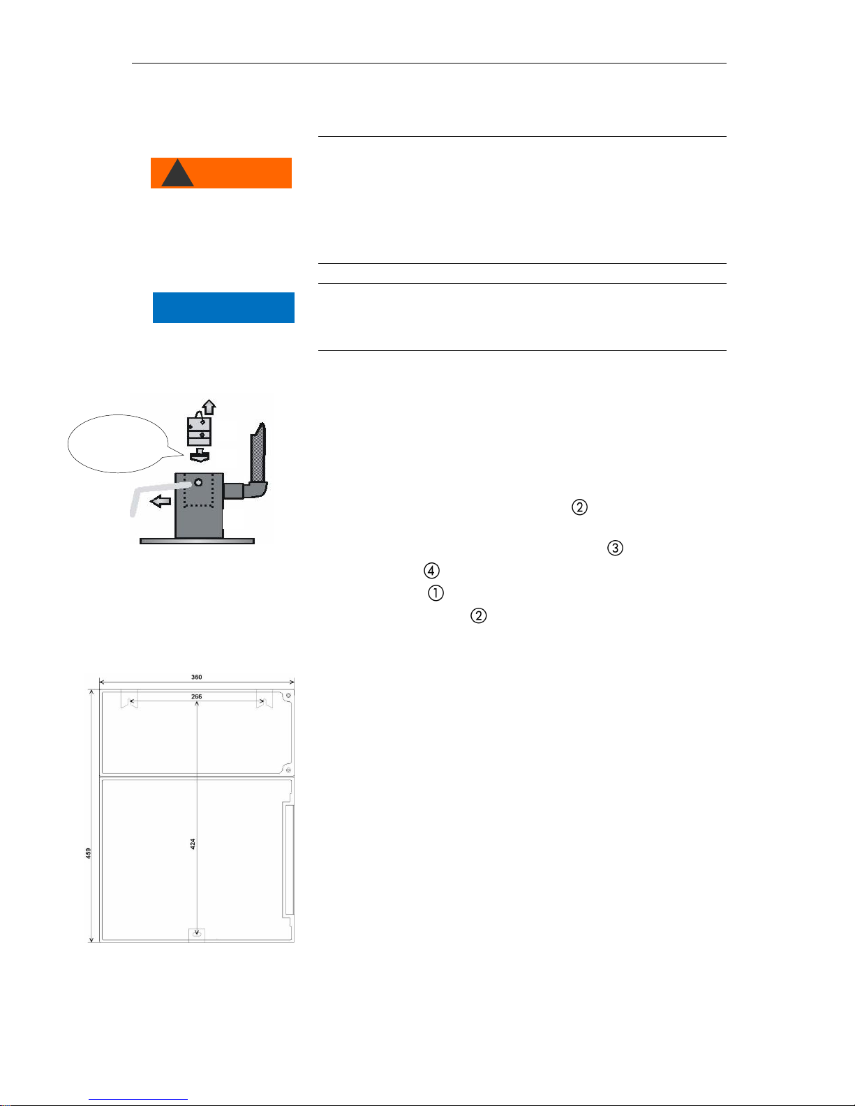
Installation...........................................................................................9
Operating Testomat 2000®Fe in the pressure range 0.3 to 1 bar........9
Installing Testomat 2000®Fe................................................................9
Connecting the water inlet and outlet .................................................10
Water inlet...........................................................................................10
Water outlet.........................................................................................10
Connecting the power supply and devices .........................................11
Block diagram Testomat 2000®Fe .....................................................11
Internal design Testomat 2000®Fe ....................................................12
Connecting the mains voltage.............................................................13
Connecting the plant components ......................................................14
Connecting the inputs and outputs .....................................................15
Commissioning.................................................................................16
Inserting reagent bottles .....................................................................16
Filling the reagent ...............................................................................16
Opening the water inlet.......................................................................16
Instrument settings and data input......................................................17
Functions of the operating and display elements.........................17
Switching Testomat 2000® Fe on/off...................................................17
Display functions.................................................................................18
Operating elements and function keys ...............................................19
Operating system................................................................................20
Password protection and basic program.......................................21
Entering basic program data...............................................................21
Selecting the operating mode.............................................................21
Selecting the displayed unit................................................................24
Entering further basic program data ..............................................25
Internal flushing...................................................................................25
External flushing .................................................................................25
Interval pause .....................................................................................26
Limit value monitoring.........................................................................26
Hysteresis ...........................................................................................27