Leslie Heritage 122H User manual

Leslie Heritage Series
Model 122H/142H
Owner’s Manual
Innovative Sound Systems
00457-40211 V1.00-220713

Leslie 122H/142H Owner’s Manual
2IMPORTANT SAFETY INSTRUCTIONS
Read these instructions.
Keep these instructions.
Heed all warnings.
Follow all instructions.
Do not use this apparatus near water.
Clean only with dry cloth.
Do not block any ventilation openings.
Install in accordance with the manufacturer’s instructions.
Do not install near any heat sources such as radiators, heat registers,
stoves or other apparatus (including ampliers) that produce heat.
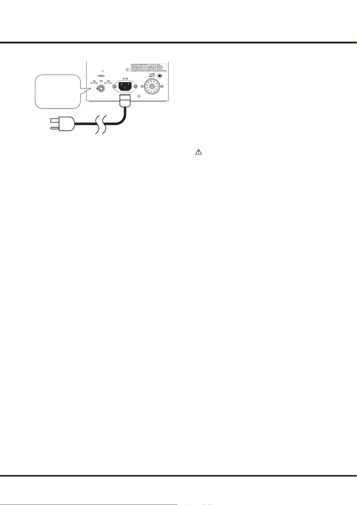
Do not defeat the safety purpose of the polarized or grounding-type
plug. A polarized plug has two blades with one wider than the other.
A grounding type plug has two blades and a third grounding prong.
The wider blade or third prong is provided for your safety. If the pro-
vided plug does not t into your outlet, consult an electrician for re-
placement of the obsolete outlet.
Protect the power cord from being walked on or pinched, particu-
larly at plugs, convenience receptacles, and the point where they exit
from the apparatus.
Only use attachments/accessories specied by the manufacturer.
Use only with the cart, stand, tripod, bracket,
or table specied by the manufacturer, or sold
with the apparatus. When cart is used: use cau-
tion when moving the cart/apparatus combi-
nation to avoid injury from tip-over.
Unplug this apparatus during lightning storms,
or when unused for long periods of time.
Refer all servicing to qualied service personnel. Servicing is required
when the apparatus has been damaged in any way, such as power-
supply cord or plug is damaged, liquid has been spilled or objects
have fallen into the apparatus, the apparatus has been exposed to
rain or moisture, does not operate normally, or has been dropped.
Apparatus shall not be exposed to dripping or splashing and no ob-
jects lled with liquids, such as vases, shall be placed on the appara-
tus.
WARNING: To reduce the risk of re or electric shock, do not expose
this apparatus to rain or moisture.
ATTENTION: Pour réduire les risques de choc électrique ou
d’incendie, ne pas exposer cet appareil à la pluie ou à l’humidité.
This mark on the unit warns that there are rotating parts inside this
unit and there is a risk of getting your ngers caught.
This mark on the unit indicates that there are hot parts inside this unit.
CAUTION
RISK OF ELECTRIC SHOCK
DO NOT OPEN
ᵈᗧ㧦ᗵ㔚ߩᕟࠇࠅࠠࡖࡆࡀ࠶࠻ࠍߌࠆߥ
ATTENTION: RISQUE DE CHOC ELECTRIQUE NE PAS OUVRIR
WARNING:
TO REDUCE THE RISK OF FIRE OR ELECTRIC SHOCK,
DO NOT EXPOSE THIS APPLIANCE TO RAIN OR MOISTURE.
-THIS APPARATUS MUST BE EARTHED.
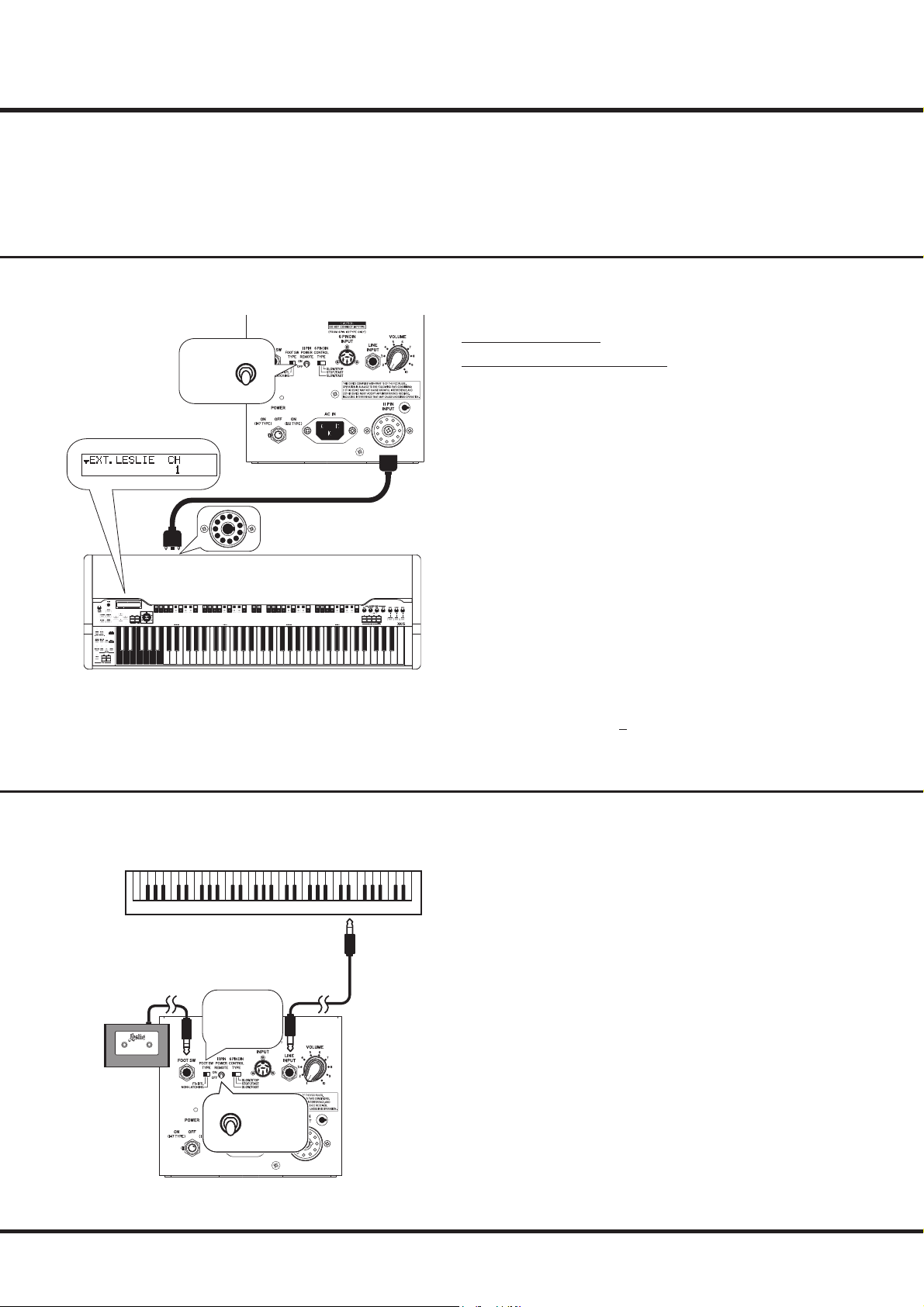
-The socket-outlet shall be installed near the apparatus and shall be easily accessible.
The lightning ash with arrowhead symbol within an equilateral tri-
angle, indicates that dangerous voltage constituting a risk of electric
shock is present within this unit.
The exclamation point within equilateral triangle, indicates that there
are important operating and maintenance instructions in the litera-
ture accompanying this unit.
WARNING: Do not insert your ngers through the gaps. There are
rotating parts and hot parts inside.

3
NOTE: This equipment has been tested and found to comply with the limits for a Class B digital unit, pursuant to
part 15 of the FCC rules. These limits are designed to provide reasonable protection against harmful interference
in a residential installation. This equipment generates, uses and can radiate radio frequency energy and, if not
installed and used in accordance with the instructions, may cause harmful interference to radio communications.
However, there is no guarantee that interference will not occur in a particular installation. If this equipment does
cause harmful interference to radio or television reception, which can be determined by turning the equipment
o and on, the user is encouraged to try to correct the interference by one or more of the following measures:
Reorient or relocate the receiving antenna.
Increase the separation between the equipment and receiver.
Connect the equipment into an outlet on a circuit dierent from that to which the receiver is connected.
Consult the dealer or an experienced radio/TV technician for help.
This class B digital apparatus complies with Canadian ICES-003.
Cet appareil numérique de la classe B est conforme à la norme NMB-003 du Canada.
In case in the future your instrument gets too old to play/use or malfunctions beyond repair, please observe the
instructions of this mark, or, if any question, be sure to contact your dealer or your nearest town or municipal oce
for its proper disposal.
FOR YOUR SAFETY, PLEASE READ THE FOLLOWING TEXT CAREFULLY
This appliance is supplied with a molded 3-pin mains plug for your safety and convenience.
The plug contains a 13 amp fuse.
Should the fuse need to be replaced, please ensure that the replacement fuse has a rating of 13 amps and that it is
approved by ASTA or BSI to BSI1362.
Check for the ASTA mark or the BSI mark on the body of the fuse.
If the plug contains a removable fuse cover, you must ensure that it is retted when the fuse is replaced.
If the fuse cover is lost, the plug must not be used until a replacement cover is obtained.
A replacement fuse cover can be obtained from your local Hammond Dealer.
IF THE FITTED MOULDED PLUG IS UNSUITABLE FOR THE SOCKET OUTLET IN YOUR HOME,
THEN THE FUSE SHOULD BE REMOVED AND THE PLUG CUT OFF AND DISPOSED OF SAFELY.
THERE IS A DANGER OF SEVERE ELECTRICAL SHOCK IF THE CUT-OFF PLUG IS INSERTED
INTO ANY 13 AMP SOCKET.
To replace the fuse, open the fuse compartment with a screwdriver and replace the fuse and fuse cover.
For the USA
For CANADA
For EU countries
For UNITED KINGDOM

Leslie 122H/142H Owner’s Manual
4THANK YOU
for your purchase of the Leslie® Speaker System. Your new Leslie Speaker culminates many years
of research and dedication to the art of sound reproduction. is Leslie Speaker has been designed
to provide the utmost in musical enchantment, plus dependable service.
e Leslie Speaker system sets revolutionary new standards of organ speaker performance,
achieving heights of musical excellence never before considered possible. Not just another speaker -
it marks a major breakthrough in organ sound, perhaps the most signicant step forward since the
introduction of the electronic organ.
Many features have been included in the speaker to insure the nest organ sound possible. Please
take a moment to read this manual, then turn on your new Leslie Speaker and enjoy your organ
playing to the fullest.
MAIN FEATURES
e Leslie Heritage Series (models 122H & 142H) is a meticulous recreation of the original Leslie 122/142
tonecabinets. Not only speakers and ampliers, but all the other elements related to the sound such as materi-
als and shapes of cabinets and rotors are recreated.
ese models include both 122 and 147 response curves, thereby enabling you to have two dierent sound
proles in the same cabinet.
e vacuum tube (valve) preamplier and power amplier give you the same classic warm sound as in the
original speaker cabinets.
ese cabinets feature three input connectors - an 11-pin plug for connecting Hammond Organs such as XK-
3, XK-3c, XK-5, etc., a LINE INPUT jack for connecting instruments with standard 1/4" LINE OUT audio
connections, and a 6-PIN DIN INPUT socket for connecting an organ equipped with a 5-pin or 6-pin tone
cabinet connector (B-3, C-3, RT-3, A-100 and D-100).
e brushless DC Servo motors are not aected by power frequency variations or voltage changes, making
them more stable under all performing conditions. ese motors give you the ability to adjust the Slow and
Fast speeds and Rise and Fall Times of the rotors.

5
SPECIFICATIONS
TYPE
1-channel (Rotary Channel Only)
Mechanical Rotors
POWER OUTPUT
40 Wrms
SPEAKERS
Horn
High-compression Driver
Low
15˝ (38cm) Woofer
Vacuum Tubes
Preamp
12BH7 x 1
Power amp
12AU7 x 1, 6550 x 2
CONTROL
Volume
Master Volume
Switch
POWER Switch, FOOT SW TYPE, 11-PIN POWER REMOTE,
6-PIN DIN CONTROL TYPE
MOTOR
Brushless DC Servo Motor x 2
ROTOR
Horn Rotor, Wooden Low Rotor
ROTOR ADJUST
Horn
RISE TIME, FALL TIME, SLOW SPEED, FAST SPEED
Low
RISE TIME, FALL TIME, SLOW SPEED, FAST SPEED
LED
SLOW, STOP, FAST
CONNECTORS
11-PIN INPUT,
6-PIN DIN INPUT,
Line INPUT ¼,˝ imped. 10ksensitivity 100mV (-18dBu),
FOOT SW (SLOW/FAST/STOP)
AC Inlet
POWER CONSUMPTION
160 W
DIMENSION
122H
W 74.2 X D 52.4 X H 104.3 cm
W 29.2 X D 20.6 X H 41 inches
142H
W 74.2 X D 52.4 X H 84.6 cm
W 29.2 X D 20.6 X H 33 inches
WEIGHT
122H
57.7 kg / 127.2 lbs
142H
54 kg / 119.1 lbs
OPTIONAL
11-pin Leslie Cable LC11-7M
6-pin to 6-pin DIN Adapter Cable LCA-66
Foot switch FS-10TL/FS-9H
BLOCK DIAGRAM
Low
Rotor
Horn Rotor
11-PIN INPUT
LINE INPUT
6-PIN DIN INPUT
Tube Amp
Transistor
Amp
Tube Amp
12BH7
Output
Transformer
Tube Amp
6550
Negative Feedback
(122 TYPE)
Output
Transformer
Negative Feedback
(147 TYPE)
Cross Over
Network
800Hz
LF HF
Tube Amp
12AU7
Power Amp Section
B-3/C-3-inspired
Preamp Section
Combo Preamp Section
122
TYPE
147
TYPE
Line
Transformer Volume Horn Driver
Woofer

Leslie 122H/142H Owner’s Manual
6
❶ Horn Rotor
Reproduces the treble (above 800 Hz) frequencies.
❷ Low Rotor
Reproduces the bass (below 800 Hz) frequencies.
❸ POWER Switch
Turns the power to the speaker “ON” or “OFF.”
Turn the switch to the right to enable “122-type” amp char-
acteristics. Turn the switch to the left to reproduce “147-type”
sound.
❹ Power Indicator
Indicates the power status.
Bright: Power is “ON.”
Dim: Standby mode for 11-pin Remote (p.13).
O: Power is “OFF.”
❺ AC Receptacle
Use to connect the AC power cord (included).
❻ 11-PIN INPUT socket
Use to connect an organ equipped with an 11-pin Leslie in-
terface.
❼ VOLUME knob
Controls the total volume of the cabinet.
❽ LINE IN jack
Use to connect an instrument with LINE OUT jacks using
standard 1/4" plugs.
❾ FOOT SW jack
Allows you to control the Leslie rotors using the FS-10TL or
FS-9H Foot Switch. When using the FS-9H, the rotors will
switch between SLOW and FAST each time the Foot Switch is
pressed. If the Foot Switch is pressed and held for 1.5 seconds
or longer, the Rotors will STOP.
NOTE: Use this jack only if you are connected to the cabinet via the
LINE INPUT jack. Do not connect a Foot Switch to this jack if
you are connected to this cabinet via the 11-pin INPUT or 5-to
6-pin Leslie socket.
e following (optional) foot switches can be used:
FS-10TL: Leslie foot switch.
FS-9H: non-latching, normally open type.
Other switches of the same type as FS-9H
(i.e. non-latching, normally open switches).
❿ FOOT SW TYPE selector
Selects the type of Foot Switch to be used.
FS-10TL: Use Leslie FS-10TL.
NON-LATCHING: Use Hammond FS-9H or similar “non-
latching/normally open” switch.
NAMES AND FUNCTIONS
11-PIN INPUT
LINE INPUT
6-PIN DIN INPUT
Preamp
Power Amp
Crossover
Network
Compression
Driver
Woofer
MAIN CONTROL PANELINTERNAL STRUCTURE
❶
❷
❸
❹
❺❻
❼❽
❾❿
⓫
⓬⓭

7
⓫6-PIN DIN INPUT socket
Connects an organ equipped with a 5- or 6-pin Leslie
adapter kit using a 6-pin to 6-pin DIN Adapter Cable
LCA-66 (optional).
CAUTION
The Leslie Heritage Series cabinets accept 122-type out-
put only. DO NOT attempt to connect another adapter
kit interface (such as 147, 251, etc.) to this cabinet or se-
vere damage may result. If you are not sure which type
of adapter kit is installed in your organ, contact a service
technician.
CAUTION
This socket includes 91V DC output. To prevent damage
to this cabinet and your devices, do not connect any oth-
er audio cables or devices other than the LCA-66 cable
to this jack.
⓬ 6-PIN DIN CONTROL TYPE selector
Selects the function of the Leslie speed switch when connected
using a 5- or 6-pin Leslie output socket.
NOTE:“CHORALE” is SLOW speed and “ TREMOLO” is FAST speed.
Position CHORALE TREMOLO
SLOW/STOP SLOW STOP
STOP/FAST STOP FAST
SLOW/FAST SLOW FAST
Table 1: Functions selected by 6-PIN DIN CONTROL TYPE selector
⓭ 11-PIN POWER REMOTE switch
Allows the cabinet to be turned “ON” from the power switch
of an organ connected via the 11-pin interface (p.13).
NOTE: If your instrument is not connected via the 11-pin interface,
set this switch to the “OFF” position. If it is set to “ON,” the
cabinet will not turn“ON.”

Leslie 122H/142H Owner’s Manual
8NAMES AND FUNCTIONS - continued
e Rotor Control Panel is located on the back panel of the
cabinet. ese controls allow you to customize the SLOW and
FAST speeds of both the Horn and Low Rotors as well as the
Rise (rate from STOP/SLOW to FAST) and Fall (rate from
FAST to SLOW/STOP) times of both rotors.
ese controls are normally covered by the metal nameplate;
however, they can be accessed by removing the plate as shown
in the gure below.
NOTE: Because the nameplate contains model information for the
cabinet, be sure to keep it and the knob bolts in a secure place
if you remove them.
ROTOR CONTROL PANEL ACCESSORIES
⓮/⓯ RISE TIME knob- HORN and LOW Rotors
ese allow you to adjust the time for the rotors to reach the
FAST speed from the SLOW speed or STOP. Turning them
clockwise will increase the time.
⓰/⓱ FALL TIME knob- HORN and LOW Rotors
ese allow you to adjust the time for the rotors to reach the
SLOW speed or STOP from the FAST speed. Turning them
clockwise will increase the time.
⓲/⓳ SLOW SPEED knob-HORN and LOW Rotors
ese allow you to adjust the rotor speed of the SLOW mode.
⓴/ FAST SPEED knob-HORN and LOW Rotors
ese allow you to adjust the rotor speed of the FAST mode.
NOTE:The default values for each setting are shown below. These are
the values when each control is in the center position.
RISE TIME FALL TIME SLOW SPEED FAST SPEED
HORN
ROTOR
1.8[s] 2.4[s] 44[rpm] 402[rpm]
LOW
ROTOR
7[s] 5.5[s] 42[rpm] 372[rpm]
ROTOR MODE Indicator
ese LEDs indicate the current state of the rotors.
NOTE: The three LEDs will all ash according to the speed of the
Low rotor for a few seconds after the power to the cabinet is
turned “ON.”
AC Power Cord
Connect the female end of the AC Power Cord into the recep-
tacle on the cabinet marked, “AC IN.”
⓮
⓯
⓰
⓱
⓲
⓳
⓴
Remove the nameplate
Turn these 2 knob bolts
counter-clockwise
Nameplate

9
PREPARING THE SPEAKER FOR USE
Steps:
①Make sure the power to the cabinet is “OFF.”
②Locate the AC Power Cord that came with the cabinet.
③Connect the female end of the AC Power Cord into there-
ceptacle on the cabinet marked, “AC IN.”
④Connect the 3-pronged Power Cord into a grounded AC
power outlet.
CAUTION
Do not place this unit in direct sunlight, near heat sourc-
es, or in a location subject to excessive heat or cold.
TO AC OUTLET
OFF

Leslie 122H/142H Owner’s Manual
10
CONNECTING AN ORGAN WITH AN 11-PIN LESLIE INTERFACE
MAKING THE CONNECTIONS
Applicable HAMMOND Models:
Single-channel models: B-3/C-3 mk2, New B-3/C-3 etc.
Models with channel switching: SK PRO, SKX PRO, SKX,
XK-5/-3/-3C, A-162, A-405, XB-3/-3M etc.
NOTE: This cabinet does not support 3-channel models,such as XE-1,
XT-100, XH-200, etc.
Steps:
①Connect the organ to the cabinet as shown on the left.
Cable used:
11-pin Leslie Cable LC11-7M (optional)
NOTE: You can also connect the organ to two cabinets using the 11-
pin Leslie“Y” Cable LC11Y-7M (optional).
NOTE: When using this connection, do not connect any cables or de-
vices to the FOOT SW jack, LINE INPUT jack or the 6-PIN DIN
INPUT socket. This is to insure the rotor modes will switch cor-
rectly and to prevent damage.
②Turn the [11-PIN POWER REMOTE] switch to “OFF.”
③If the organ has a provision for setting the number of chan-
nels of an external Leslie, set the [EXT.LESLIE CH] of the
connected organ at 1.
NOTE: Please refer to the Owner’s Manual of the organ for instruc-
tions on how to set the number of channels.
UPPER
BANK KEY PATCH
PEDAL LOWER
FS-10TL
SLOW / FASTON / OFF
Select the Foot
Switch Type
CONNECTING AN INSTRUMENT WITH A 1/4" AUDIO INTERFACE
Steps:
①Connect the cabinet and the instrument as shown on the left.
Cable used:
1/4˝ mono phone cable (optional)
②Turn the [11-PIN POWER REMOTE] switch to “OFF.”
③Connect a Foot Switch (FS-10TL or FS-9H) to the [FOOT
SW] jack.
NOTE: When using this connection, do not connect any cables or
devices to the 11-PIN INPUT socket or the 6-PIN DIN INPUT
socket. This is to insure the rotor modes will switch correctly
and to prevent damage.
④Select the Foot Switch Type using the [FOOT SW TYPE]
selector. Position it to the left [FS-10TL] when using an FS-
10TL and to the right [NON-LATCHING] when using a
Hammond FS-9H or similar “non-latching/normally open”
switch.
NOTE: If your instrument has a built-in digital Leslie, turn it “OFF”
when using this connection.
Connect cables and accessories and operate the switches on this unit as shown below and
on the next page.
NOTE: Make sure the power to both the instrument and the cabinet is “OFF” before making any
of the following connections.
NOTE: Do not connect any cables or devices other than those shown in each of the following con-
nections. This is to insure the rotor mode will switch correctly and to prevent damage to
either the organ or the speaker cabinet.
11-pin Leslie Cable
LC11-7M
OFF
Leslie 11-pin socket
1/4˝ mono phone cable
FS-10TL or FS-9H
(or similar “non-latching/
normally open” switch)
OFF

11
16 16
CONNECTING AN ORGAN WITH A 5- or 6-PIN LESLIE INTERFACE
WARNING: Risk of Electric Shock!
Make sure the power to both the organ and the cabinet
is “OFF” before performing any of the steps shown be-
low. Do not touch the pins of the cables while power is
“ON,” or electric shock may result due to voltage emitted
from the organ and the cabinet.
Steps:
①Connect this unit and the organ as shown in the gure on
the left.
Cables used:
6-pin to 6-pin DIN Adapter Cable LCA-66 (optional)
5-pin to 6-pin Leslie Adapter Cable/
6 conductor Leslie Cable
NOTE: When using this connection, do not connect any cables or de-
vices to the FOOT SWITCH jack, LINE INPUT jack or the 11-PIN
INPUT socket. This is to insure the rotor modes will switch cor-
rectly and to prevent damage.
CAUTION
The Leslie Heritage Series cabinets accept 122-type out-
put only. DO NOT attempt to connect another adapter kit
interface (such as 147, 251, etc.) to this cabinet or severe
damage may result. If you are not sure which type of adapt-
er kit is installed in your organ, contact a service technician.
CAUTION
Be sure to notice the orientation of the connectors (shown
at left).
②Make sure the [11-PIN POWER REMOTE] switch is
“OFF.”
NOTE: The 11-PIN POWER REMOTE function is not supported when
using the 6-PIN DIN INPUT interface (p.13).
③Select the function of the Leslie speed switch using the [6-
PIN DIN CONTROL TYPE] selector (p.7).
CAUTION
The 6-PIN DIN INPUT socket includes 91V DC output. To
prevent damage to this cabinet and your devices, do not
connect any other audio cables or devices other than the
LCA-66 cable to this jack.
Column: Difference between 122 and 147-type Leslie Input
Pin Number Leslie 122 Leslie 147
1st signal input (balanced) signal GND
2nd AC signal/DC GND speed control AC voltage
3rd AC power input AC power input
4th AC power input AC power input
5th DC 265V output (B+) speed control AC voltage
6th signal input (balanced) signal input (unbalanced)
Table: function of Leslie 6-pin input socket
Leslie Speaker models 122 and 147 both use a 6-pin interface;
however, the pin congurations are dierent for the two cabi-
nets (see the table on the left).
NOTE: Before attempting to connect the Heritage Series cabinets
to a vintage organ, the organ needs to have a Leslie speed
switch attached to the front rail.
Risk of Electric Shock
Do not touch the pins on
the cables while power is
“ON.”
WARNING
5-pin tone cabinet
connector
Select the
function of the
Leslie switch
5-pin to 6-pin
Leslie Adapter Cable
OFF
Male Female
1st pin and 6th pin
are slightly thicker.
position dot
6 conductor
Leslie Cable
6-pin Leslie
output socket
6-pin to 6-pin DIN
Adapter Cable LCA-66

Leslie 122H/142H Owner’s Manual
12 POWER ON
After making the connections described on the previous pages, fol-
low the procedures on this page to turn the power to the cabinet
“ON.” Please follow these procedures to prevent malfunction or
damage.
Steps:
①Turn the [VOLUME] knob to its minimum position as
shown on the left.
②Turn the power to the connected instrument ON.
③Turn the [POWER] Switch to “ON (122 TYPE)” or “ON
(147 TYPE).”
The rotors will automatically start rotating at FAST mode.
After 6 seconds, the rotors will switch from FAST mode to the cur-
rent speed according to the position of the Leslie switches on the
organ or the Foot Switch setting.
NOTE: If you are switching from one Type to another, turn the Power
Switch “OFF,” and wait about 2 seconds before turning it to
the other position.
④Turn the volume of the connected instrument to its maxi-
mum position.
⑤Adjust the [VOLUME] knob of the cabinet while playing
the instrument to determine the appropriate setting.
NOTE: The vacuum tubes utilized in this cabinet require approxi-
mately 10 to 20 seconds to warm up after the power is turned
“ON.” After the tubes have warmed up the cabinet will sound.
CAUTION
The [VOLUME] knob should be set to a moderate amount
in order to prevent distortion or overdriving the speak-
ers (see the illustration on the left). Excessive volume may
cause serious damage to the unit.
⑥Verify that the Rotor speeds will change in response to either
the Leslie switches on the connected instrument or a Foot
Switch.
①
③
⑤
NOTE: When you are using the 6-PIN DIN
INPUT socket, the audio signal goes
directly to the power amp circuit but
does not go through the preamp cir-
cuit.
Hammond
Organs
Organs made by
the company W
Organs made by
the company L
Optimized sound
for Hammond Organ
Sound which ts with
many organs
Column: Difference in sound between Leslie 122 and 147
Leslie Speaker models 122 and 147 share the same cabinetry
but contain dierent electronics and are designed for dierent
applications. e 122 was originally designed specically for
Hammond Organs requiring a separate tone cabinet (B-3, C-3,
RT-3, etc.). e 147 was designed for single channel organs
having the sound-producing circuitry within the console (A-
100 as well as organs of other brands) and has dierent input
circuitry relating to rotor speed switching (see the table at the
bottom of page 11).
Although the 122 and 147 cabinets both utilize a 40-watt tube
amplier, the sound is slightly dierent on the two cabinets.
e 147 is slightly brighter due to a higher treble roll-o fre-
quency.
Leslie 122/147 and 142/145
The Leslie 122 and 147 both utilized cabinets
with a height of 41 inches. However, both mod-
els were also oered in slightly smaller cabinets
(33 inches in height) for special applications.
The model 142 is the smaller version of the 122
and the 145 is the smaller version of the 147.
122-type power amp circuit
and the tube preamp circuit
built in B-3/C-3.
147-type power amp
circuit and the transis-
tor (solid-state) combo
preamp circuit.
Organs made by
the company G
Hammond
Organs

13
11-PIN POWER REMOTE FUNCTION
(only for organs with a Leslie 11-pin socket)
If you are connected to the cabinet using the 11-pin interface,
you can use the 11-PIN POWER REMOTE function to turn the
power to the cabinet “ON” using the power switch on the organ.
NOTE: This function is only available when connecting the cabinet
using the 11-pin interface.
Steps:
①Make sure the power to both the organ and the cabinet are
“OFF.”
②Connect the cabinet to the organ using the 11-pin interface
(optional Leslie Cable LC11-7M).
③Turn the [11-PIN POWER REMOTE] switch to “ON.”
④Turn the [POWER] Switch on the cabinet to “ON (122
TYPE)” or “ON (147 TYPE).”
The Power Indicator LED will light“Dim,”indicating the cabinet is in
STANDBY mode.
⑤Turn the power to the organ “ON.”
The cabinet and the organ will both turn“ON” and the Power Indi-
cator LED will light “Bright.”
NOTE:If you turn the power to the connected organ "OFF," the cabi-
net will revert to STANDBY mode and the Power Indicator LED
will light “Dim.”
UPPER
BANK KEY PATCH
PEDAL LOWER
11-pin Leslie Cable
LC11-7M
ON
Leslie 11-pin socket

SERVICE
Hammond maintains a policy of continuously improving and upgrading its instruments and therefore reserves the
right to change specications without notice. Although every attempt has been made to insure the accuracy of the
descriptive contents of this Manual, total accuracy cannot be guaranteed.
Should the owner require further assistance, inquiries should rst be made to your Authorized Hammond Dealer.
If you still need further assistance, contact Hammond at the following addresses:
In the United States Contact:
HAMMOND SUZUKI USA, Inc.
219 West Wrightwood Ave. Elmhurst,
Illinois 60126
UNITED STATES
Tel: (630) 543-0277
Fax: (630) 543-0279
Web site: www.hammondorganco.com
E-mail: info@hammondorganco.com
In European countries contact:
HAMMOND SUZUKI EUROPE B. V.
IR. D. S. Tuynmanweg 4a 4131 PN Vianen
THE NETHERLANDS
Tel: (+31) 347-370 594
Web site: www.hammond.eu
E-mail: [email protected]
For other countries:
SUZUKI CORPORATION
2-25-7, Ryoke, Naka-ku, Hamamatsu,
Shizuoka Pref. 430-0852
JAPAN
Tel: (+81) 53-460-3781
Fax: (+81) 53-460-3783
E-mail: suzukicorp@suzuki-music.co.jp
Manufacturer:
SUZUKI MUSICAL INSTRUMENT MFG. Co., Ltd.
2-25-7, Ryoke, Naka-ku, Hamamatsu, Shizuoka Pref. 430-0852
JAPAN
Product Registration
http://hammondorganco.com/support/
online-product-registration/
Product Registration
http://www.hammond.eu/support/
online-product-registration/
Technical materials are available and can be obtained by mailing a request to the appropriate address listed above
marked ATTENTION: SERVICE DEPARTMENT.
This manual suits for next models
1
Table of contents
Other Leslie Speakers manuals