7
SPA-150R-L Owner’s Manual
POWER CABLE
is unit is powered by electricity. Before you start using it,
plug the power cable into the AC IN jack and the power plug
into the AC outlet securely. Aer using it, pull the cable o
the outlet by holding the power plug.
POWER SWITCH
is is the switch to turn [ON/OFF] this unit. While the
power is ON, the power indicator lights on.
Make sure the power is OFF before you connect any external
equipment to this unit, and prevent noise.
Set the Master Volume knob (12) at minimum before you
switch the power ON, thus a sudden loud sound is avoided.
is unit is designed not to produce sound for the rst ap-
prox. 3 seconds aer switched on, for protection of the inter-
nal circuits.
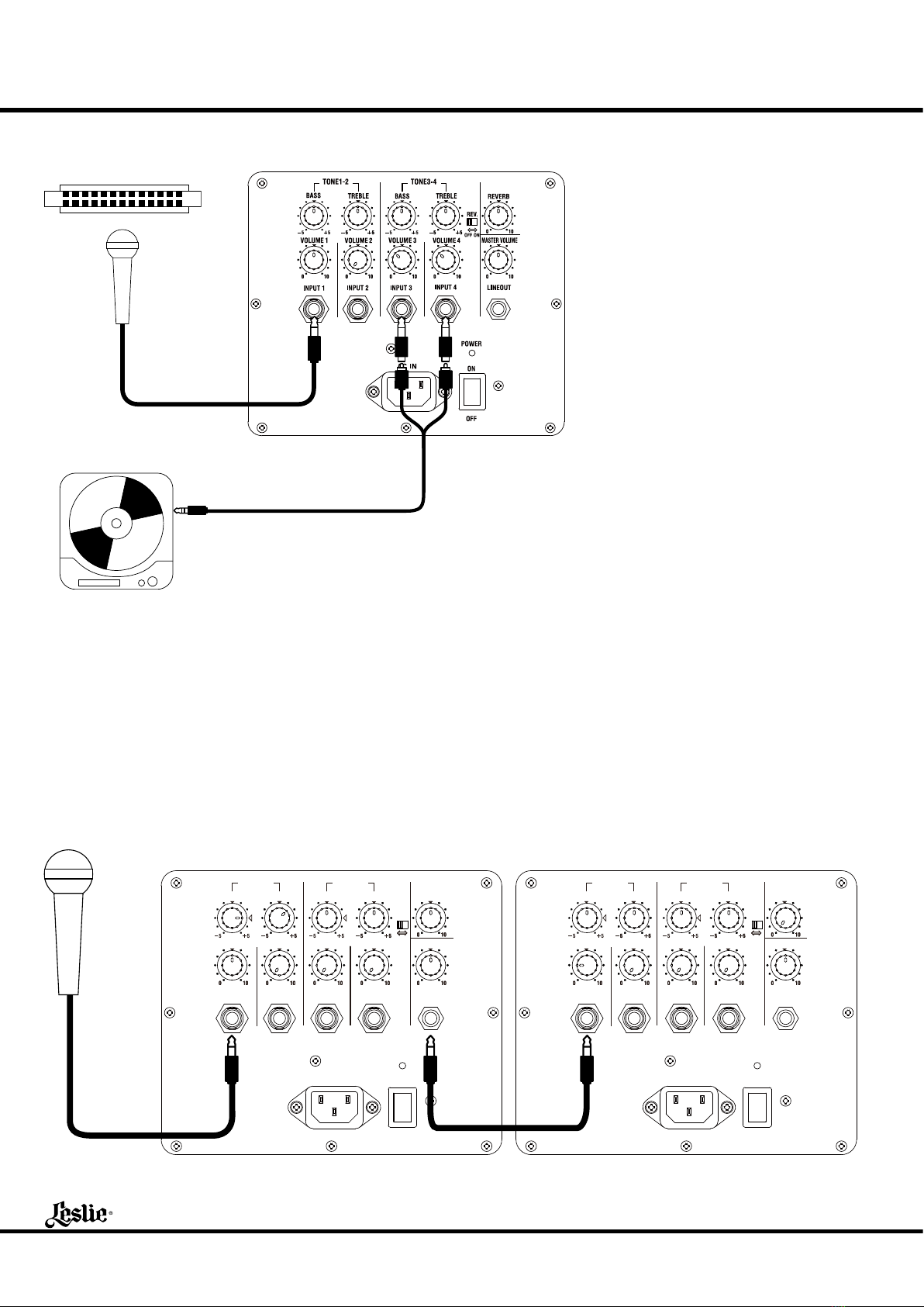
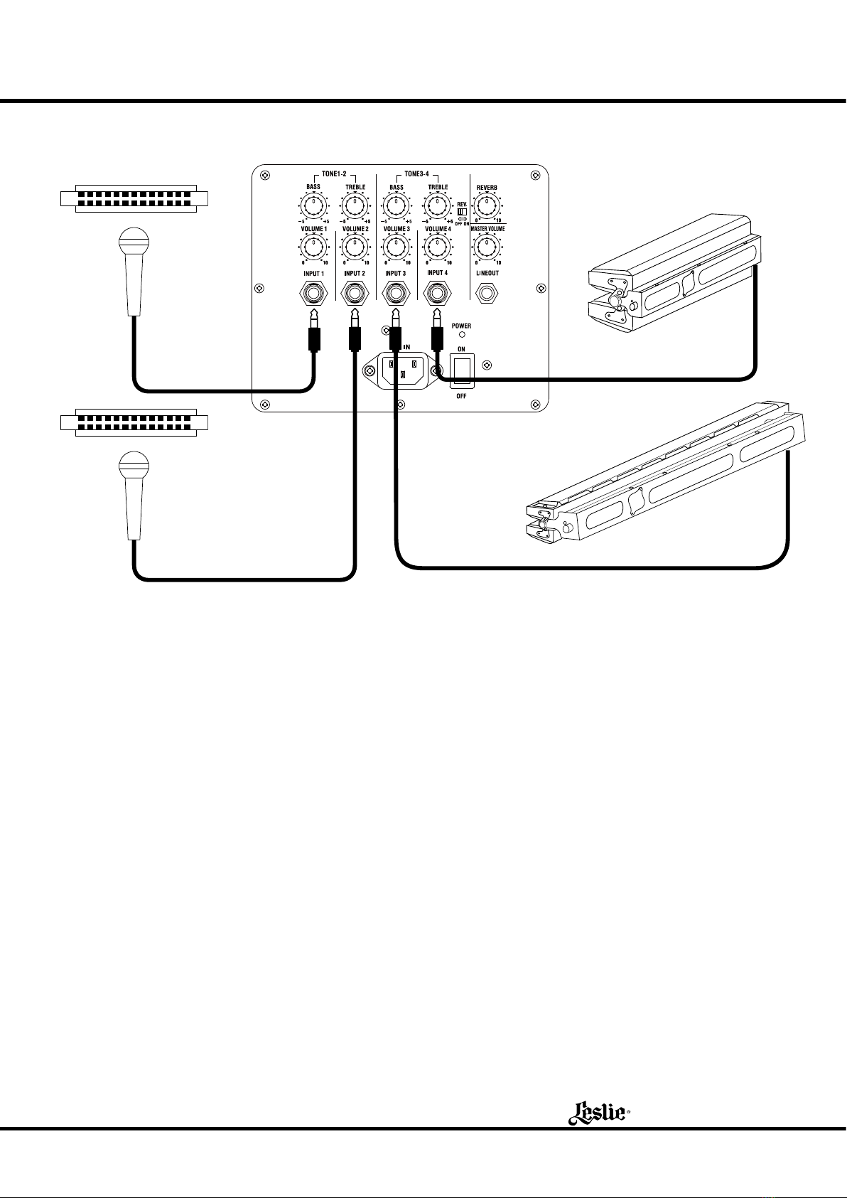
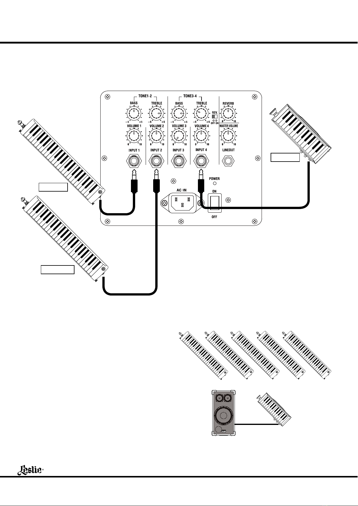
to INPUT 1 - 4 JACK
ese are voice input terminals. You can connect such exter-
nal equipment as mics, Melodions, keyboards, a CD player,
etc. from the level of mic to line. e terminals are monaural
¼˝ phone jacks.
LINE OUT JACK
is is an output terminal for connecting to a recorder or an-
other amplier for obtaining more volume. e output is line
level, and the terminal is a monaural ¼˝ phone jack.
to VOLUME KNOBS 1 - 4
ey control the volume of the external equipment connect-
ed to the input jack. At 0, it does not sound. Turning the knob
to the right increases the volume.
MASTER VOLUME KNOB
is knob controls the volume of the entire unit.
You can reduce the noise to a minimum by setting the Vol-
ume Knobs 1 - 4 as high as possible within the limit that no
distortion appears and then get the desired volume by adjust-
ing the Master Volume.
Also, use this knob, if you want to temporarily turn o the
sound, maintaining the balance among the Knobs 1 - 4.
to TONE KNOBS 1 - 2
ese knobs adjust the tonal quality of the INPUT 1 and IN-
PUT 2.
e standard setting is at the center. Heaviness of the sound
increases, if you raise the Bass. And, if you drop the Bass, it
decreases and also the wind noise reduces, while a micro-
phone is connected. If you raise the Treble, brilliance of the
sound increases. If you lower it, the sound gets so.
e [BASS] knob has a special function: At center, it is elec-
trically at. And at “”, it makes up the sub-bass of woofer
with slightly bass boost.
to TONE KNOBS 3 - 4
ese knobs control the sound quality of INPUT 3 and IN-
PUT 4.
REV. SWITCH
is switch sets whether or not to add the reverb eect to
INPUT 3 and INPUT 4. If you turn o this switch, no reverb
eect is added to the INPUTS 3 or 4.
Regardless of the position of this switch, the reverb eect is
always added to the INPUT 1 and INPUT 2, as set by the
REVERB Knob (18).
REVERB KNOB
is is for adding the reverb eect to the sound as if in the
concert hall.
No reverb eect is added at 0. If you turn the knob to the
right, the eect deepens.
HANDLE
is handle is for transportation.
POLE SOCKET
is socket is for mounting the unit on to the speaker stand
(not included - optional).
is corresponds to a pole of 35mm (1⅜˝) in diameter
(thickness).
CAUTION
Please be careful when mounting it to the speaker stand.
w Place the stand on a at stable surface.
w Use the stand at lowest height (TS-70B) or under 1.3m (4´
3˝) (others).
w Use the stand by fully opening the legs.
w Don’t let anybody come near the stand unnecessarily.
w Use one stand for one unit.
w Use only the designated screws for assembly.
w Securely tighten the screws.
w Detach the unit before you move the stand or adjust the
height.
HIGH TEMPERATURE PROTECTION CIRCUIT
If you continue using this unit at a large volume, the internal
temperature rises and it may stop functioning. In such a case,
stop using this unit until the temperature goes down and it
functions again.
If the temperature goes up frequently, use this unit at a lower
volume.
You need not switch o the power while the unit is being
cooled down.