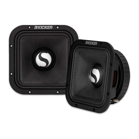
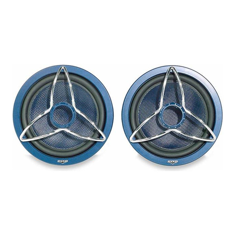
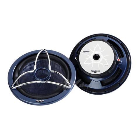
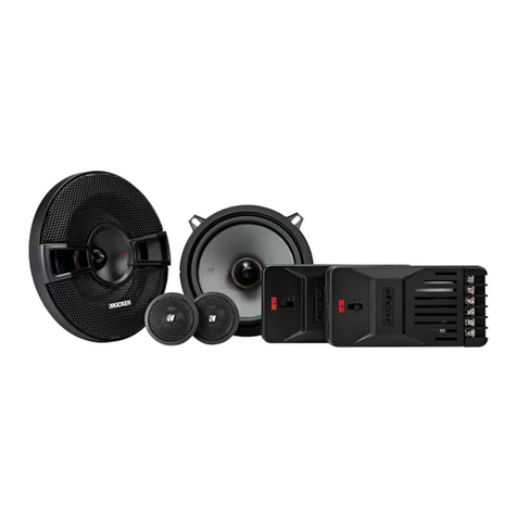
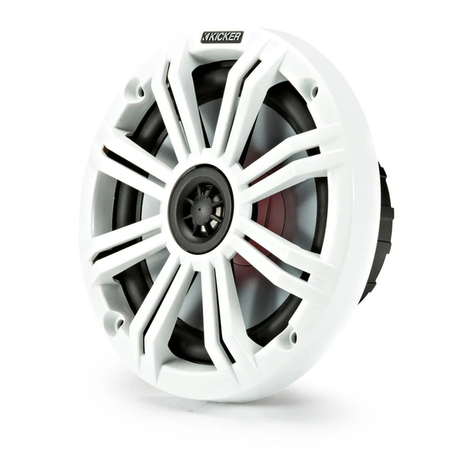
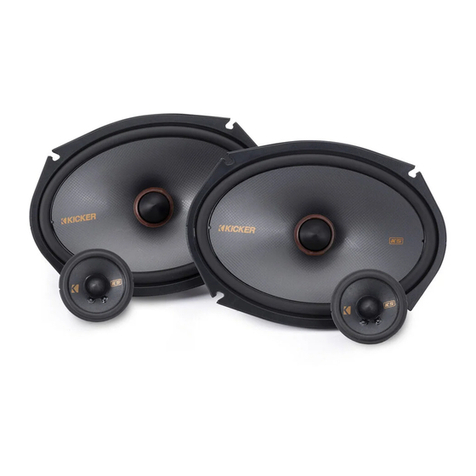
Kicker KSS50 User manual

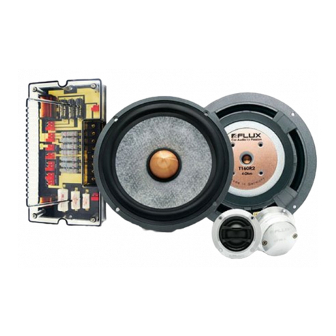
KS COMPONENT SPEAKERS
KSS50 | KSS650 | KSS670
Owner’s Manual | English
Manual del Propietario | Español
Altavoz Componentes KS
Benutzerhandbuch | Deutsch
KS Komponenten-System
Manuel d’utilisation | Française
Haut-parleurs Composants KS
KSS Speakers
2017 KS Component Rev B.indd 12017 KS Component Rev B.indd 1 8/23/2016 12:22:38 PM8/23/2016 12:22:38 PM

2
KS COMPONENT SYSTEM
Owner’s Manual
MODELS: KSS50 | KSS650 | KSS670
PERFORMANCE
KS COMPONENT SPEAKERS
The KICKER KS speakers offer an excellent upgrade to your vehicle’s factory sound system, delivering great
full-range sound at an amazing value! Whether dropping the KS speakers in a factory location or customizing
your install, their high-efficiency design means less power is needed to play your music, while our use of
advanced materials and construction techniques ensures optimal performance for years to come.
IMPORTANT SAFETY WARNING
Prolonged continuous operation of an amplifier, speaker, or subwoofer in a distorted, clipped or over-
powered manner can cause your audio system to overheat, possibly catching fire and resulting in serious
damage to your components and/or vehicle. Amplifiers require up to 4 inches (10cm) open ventilation.
Subwoofers should be mounted with at least 1 inch (2.5cm) clearance between the front of the speaker and
any surface.
KS Component Speakers KSS50 KSS650 KSS670
Woofer [in, mm] 5-1/4, 130 6-1/2, 160 6-3/4, 165
Tweeter [in, mm] 1, 25 1, 25 1, 25
Dome Material Silk Silk Silk
Rated Impedance [Ω] 4 4 4
Peak Power Handling [ Watts] 200 250 250
Continuous Power Handling [Watts RMS] 100 125 125
Sensitivity [1W, 1m] 88 90 91
Frequency Response [Hz] 38-21k 35-21k 35-21k
Woofer Mounting Hole Diameter [in, mm] 4-1/2, 115 4-13/16, 123 5-9/16, 141
Woofer Top Mount Depth [in, mm] 1-3/4, 45 1-13/16, 46 1-13/16, 46
Flush Mount Tweeter Hole Diameter [in, mm] 1-3/4, 45 1-3/4, 45 1-3/4, 45
Flush Mount Tweeter Depth [in, mm] 11/16, 17 11/16, 17 11/16, 17
High Pass [dB], at Frequency [Hz] 12, 4,000 12, 4,000 12, 4,000
Low Pass [dB], at Frequency [Hz] 12, 4,000 12, 4,000 12, 4,000
High Frequency Output Attenuation [dB] 0, 4.5, 9 0, 4.5, 9 0, 4.5, 9
Note: All specifications and performance figures are subject to change. Please visit www.kicker.com for the
most current information. To get the best performance from your new KICKER speakers, we recommend using
genuine KICKER accessories and wiring. Please allow two weeks of break-in time for the speakers to reach optimum
performance.
Pro Tip: You’re a KICKER amplifier and a few cables away from a full system upgrade that will dominate
any factory system! KICKER line of amplifiers make it easy to upgrade to solid bass with your existing or
stock source unit. Also, ask your dealer about KICKER Subwoofer upgrades.
2017 KS Component Rev B.indd 22017 KS Component Rev B.indd 2 8/23/2016 12:22:40 PM8/23/2016 12:22:40 PM

3
CONFIGURATION
Before mounting and wiring the KS component system, determine which configuration you will use for the
speakers.
KS Speaker
Configurations ADVANTAGES CONSIDERATIONS
Coaxial great for space-limited applications
or when separate tweeter mounting
is not possible
high frequencies may not be as
prominent | tweeter output may
need to be increased at crossover
Separates optimal sound quality and improved
sonic imaging (with proper tweeter
mounting)
trickier install | vehicle must have a
good tweeter mounting location
2.
5.
1.
4.
remove phase plug
screw tweeter post to speaker
Attach tweeter back to tweeter
snap tweeter to tweeter post
thread tweeter wire through post and speaker
Coaxial Configuration
3.
The KS speakers come in a separates configuration. For coaxial operation, use the following steps to
attach the tweeter.
2017 KS Component Rev B.indd 32017 KS Component Rev B.indd 3 8/23/2016 12:22:40 PM8/23/2016 12:22:40 PM
4
CROSSOVER & WIRING CONFIGURATION
We recommend using 16 gauge (or larger) wire. The KS Speakers
are rated at 4 ohms and work with any source unit or amplifier
designed to operate at a 4 ohm load. Make sure your source
unit or amplifier is rated for 4 ohm operation.
Use the tweeter attenuation switch to adjust the output level of
the tweeter to 0 dB, +4.5 dB, or +9 dB.
Higher switch settings will
result in more volume from the tweeter.
+-
+
+
-
-
+
-
+
+
+
-
-
-
+
+
+
-
-
-
crossover
Crossover Wiring
Two component sets per channel
Crossover Wiring
One component set per channel
source unit / amplifier
At least two amplifier channels are needed for
stereo operation (only one channel is shown)
Requires two complete KS systems
(four woofers, four tweeters, four crossovers)
At least two amplifier channels
are needed for stereo operation
(only one channel is shown)
Crossovers wired in parallel. Make sure your source
unit or amplifier is rated for 2 ohm operation.
2017 KS Component Rev B.indd 42017 KS Component Rev B.indd 4 8/23/2016 12:22:40 PM8/23/2016 12:22:40 PM
5
door jamb
KS crossover. (mounted
inside door panel)
rubber grommets from amplifier or
source unit
woofer mounting hole
tweeter mounting hole
to woofer terminals
to tweeter lead wires
CROSSOVER MOUNTING
Mount the crossover in a location that is easy to access for wiring and tweeter output level adjustment.
Make sure that the crossover will not be exposed to water. The bottom of the car door is not a good
location. If you must mount the crossover in the car door, exercise caution as water can accumulate in the
bottom of the door. Keep the crossover high in the door and shielded from water.
If factory speaker wiring is not available in your desired location, it may be necessary to run speaker wire
through the door jamb. The speaker wire should be kept away from sharp edges and avoid the possibility of
getting pinched by the door. An existing grommet in the door jamb is the ideal place to run the speaker wire.
If the factory hole and grommet do not exist or are inaccessible, you must drill a hole to run the speaker wire
through the door jamb. Be careful not to drill into other wiring or existing door mechanisms. Any time a wire
is run through a hole, it is necessary to insert a rubber or plastic grommet to protect the wire from damage.
2017 KS Component Rev B.indd 52017 KS Component Rev B.indd 5 8/23/2016 12:22:40 PM8/23/2016 12:22:40 PM

6
door
door panel
speaker cut-out
KS speaker
SPEAKER MOUNTING
The KICKER KS Speakers are designed for free-air applications and do not require a sealed enclosure for
optimum performance. It is important to isolate the sound coming from the front of the speaker from the
sound radiating from the back of the speaker. This is most easily accomplished by mounting the speakers
in a vehicle’s factory locations or in a location with a semi-isolated rear chamber (like the rear deck of a car
behind the rear seats).
If you are replacing factory speakers in their original locations, you may have to enlarge the speaker cut-
outs and pre-drill new screw holes using a 7/64” (2.5mm) bit. Custom mounting locations will require more
preparation and work. Make sure that the speaker will not interfere with trunk and door opening and closing
mechanisms and that the enclosed screws will not puncture the fuel tank, puncture wiring, or interfere with
any other mechanical parts on the underside of the mounting surface. Cycle the windows all the way down
and up.
If the speaker cut-out locations require you to cut metal, avoid structural metal and braces. If the door body
and panel cannot support the weight of the speaker, an optional reinforcing ring (thin piece of wood or
Medium Density Fiberboard) may be fastened or adhered to the door body.
2017 KS Component Rev B.indd 62017 KS Component Rev B.indd 6 8/23/2016 12:22:40 PM8/23/2016 12:22:40 PM
7
TWEETER MOUNTING
The tweeter can be separately mounted one of three ways: flush, angled and surface. For flush mounting
applications, choose a flat location on the panel with space behind the panel to allow room for the short
mounting nut, motor structure, and tweeter. After checking the clearances, cut a 1-3/4” (44mm) diameter
mounting hole in the panel. Position the short mounting nut behind the panel. Feed the wire through the
optional flush ring, the hole in the panel, and the mounting nut. Mount the tweeter by screwing the mounting
nut onto the tweeter.
For surface mounting applications use the surface mount cup as a template and pre-drill one 7/64” (2.5mm)
screw hole (using two holes is optional) for attaching the surface mount cup to the panel and a 5/16” (8mm)
hole for the wires. An M3 pan-cross head wood screw is supplied to attach the surface mount cup to the
panel. Position the tweeter over the surface mount cup and screw it into position.
For angled mounting applications choose a flat location on the panel with space behind the panel to allow
room for the long mounting nut, motor structure, tweeter post, and back angle ring. After checking the
clearances, cut a 1-3/4” (44mm) diameter mounting hole in the panel. Place the front angle ring in front of
the panel. Then place the wire and tweeter through the front angle ring and into the panel. Next, place the
wire through the back angle ring, place the back angle ring over the rear of the tweeter, and line-up the
narrow part of the front angle ring for the preferred angle of operation. Place the wire through the mounting
nut and loosely tighten the mounting nut around the tweeter. Rotate all the parts in unison until the tweeter is
angled in the desired direction. Secure the assembly by tightening the mounting nut.
panel
panel
panel
short mounting nut flush ring
tweeter
tweeter
tweeter
surface mount cup
Flush Mounting
Angle Mounting
Surface Mounting
flush ring
long mounting nut back angle ring
decrease mounting depth by
removing tweeter back cover
front angle ring
rounded surface
inset surface
2017 KS Component Rev B.indd 72017 KS Component Rev B.indd 7 8/23/2016 12:22:44 PM8/23/2016 12:22:44 PM

8
Manual del propietario del
SISTEMA DE COMPONENTES KS
COMPONENTES KS
Los sistemas de Component de la serie KS de KICKER ofrecen una fidelidad de audio inigualable para
aplicaciones para vehículos. Ya sea para configurar el último sistema de sonido envolvente con altavoces
múltiples y subwoofer o simplemente para mejorar la versión de parlantes aburridos y sin vida de fábrica,
los sistemas de Componentes KS brindan el sonido de gama completa más placentero del mercado en la
actualidad!
RENDIMIENTO
MODELO: KSS50 | KSS650 | KSS670
Altavoz Componentes KS KSS5 KSS65 KSS67
Parlante Baja Frecuencia (Woofer) [pulgada, mm] 5-1/4, 130 6-1/2, 160 6-3/4, 165
Parlante Alta Frecuencia (Tweeter) [pulgada, mm] 1, 25 1, 25 1, 25
Material para la cúpula Seda Seda Seda
Impedancia nominal [Ω] 4 4 4
Manejo de la potencia máxima [Watts] 200 250 250
Manejo de la corriente continua [Watts RMS] 100 125 125
Sensibilidad [1W, 1m]
88 90 91
Respuesta en frecuencia [Hz] 38-21k 35-21k 35-21k
Diámetro del orificio de montaje woofer [pulgadas, mm] 4-1/2, 115 4-13/16, 123 5-9/16, 141
Profundidad del montaje del woofer [pulgadas, mm] 1-3/4, 45 1-13/16, 46 1-13/16, 46
Diámetro del orificio del montaje empotrado del tweeter [pulgadas, mm] 1-3/4, 45 1-3/4, 45 1-3/4, 45
Profundidad del montaje empotrado del tweeter [pulgadas, mm] 11/16, 17 11/16, 17 11/16, 17
Paso alto [dB] frecuencia de [Hz] 12, 4,000 12, 4,000 12, 4,000
Paso bajo [dB] frecuencia de [Hz] 12, 4,000 12, 4,000 12, 4,000
Atenuación de la salida de alta frecuencia [dB] 0, 4.5, 9 0, 4.5, 9 0, 4.5, 9
IMPORTANTE ADVERTENCIA DE SEGURIDAD
Funcionamiento continuo prolongado de un amplificador, altavoz o subwoofer de una manera distorsionada,
recortado o el exceso de potencia puede hacer que el sistema de audio se sobrecaliente, posiblemente
la captura de fuego y que resulta en graves daños a sus componentes y / o vehículo. Amplificadores
requieren hasta 4 pulgadas (10 cm) de ventilación abierta. Subwoofers deben montarse con el aclaramiento
(2,5 cm) por lo menos 1 pulgada entre la parte frontal del altavoz y cualquier superficie.
Consejo profesional: ¡Usted es un KICKER Amplificador, y unos pocos cables lejos de un sistema
fuerte estéreo! KICKER amplificadores lo hace fácil de mejorar sólido como una roca bajo con su existir
estéreo. Pregunte por favor su comerciante acerca de los aumentos de Amplificador de Kicker.
2017 KS Component Rev B.indd 82017 KS Component Rev B.indd 8 8/23/2016 12:22:44 PM8/23/2016 12:22:44 PM

9
Configuración coaxial
CONFIGURACIÓN
Antes de montar y realizar el cableado del sistema de componentes KS , determine qué configuración
utilizará para los altavoces.
Configuraciones de
los altavoces KS
VENTAJAS CONSIDERACIONES
Coaxial
Excelente para aplicaciones con
espacio limitado o cuando no es posible
el montaje del tweeter por separado
Es posible que las frecuencias altas
no sean tan prominentes | Es posible
que se necesite aumentar la salida
del tweeter en el crossover
Por separado Óptima calidad de sonido y mejor
imagen acústica (con el montaje
adecuado del tweeter)
Instalación más difícil | El vehículo
debe tener una buena ubicación
de montaje del tweeter
2.
5.
1.
4.
3.
El sistema de componentes KS viene empaquetado en una configuración por separado.
Para utilizar una configuración coaxial, siga los pasos a continuación:
retire la clavija de fase
atornille el montante del altavoz de alta
frecuencia al altavoz
Adhiera el altavoz de alta frecuencia detrás del altavoz
conecte el altavoz de alta frecuencia
a su montante
pase el cable del altavoz de alta frecuencia a través del montante y altavoz
2017 KS Component Rev B.indd 92017 KS Component Rev B.indd 9 8/23/2016 12:22:45 PM8/23/2016 12:22:45 PM

10
CONFIGURACIÓN DEL CROSSOVER
Y CABLEADO
Se recomienda utilizar un cable calibre 16 (o más). Los
componentes KS están clasificados para 4 ohms y funcionan con
cualquier unidad fuente o amplificador diseñado para operar a una
carga de 4 ohms.
Asegúrese de que la unidad fuente o el amplificador estén
clasificados para funcionar con 4 ohms.
Utilice el interruptor de atenuación de agudos para ajustar el nivel
de salida del altavoz de agudos a 0 dB, +4,5 dB, o +9 dB. Si e
selecciona un valor mayor, el tweeter producirá más volumen.
+-
+
+
-
-
+
-
+
+
+
-
-
-
+
+
+
-
-
-
crossover
Crossover Cableado
Dos conjuntos de componentes por canal
Crossover Cableado
Un conjunto de componentes por canal
unidad fuente / amplificador
Se necesitan al menos dos canales para
amplificadores para el funcionamiento en
estéreo (se muestra un solo canal).
Requiere dos sistemas KS completos (cuatro
woofer, cuatro tweeter y cuatro crossover).
Se necesitan al menos dos
canales para amplificadores
para el funcionamiento en
estéreo (se muestra un solo
canal).
Crossover conectados en paralelo.
Asegúrese de que
la unidad fuente o el amplificador estén clasificados
para funcionar con 2 ohms.
2017 KS Component Rev B.indd 102017 KS Component Rev B.indd 10 8/23/2016 12:22:45 PM8/23/2016 12:22:45 PM

11
MONTAJE DEL CROSSOVER
Monte el crossover en una ubicación que sea de fácil acceso para realizar el cableado y ajustar el nivel
de salida del tweeter. Asegúrese de que el crossover no quede en un lugar que se pueda mojar. La
parte inferior de la puerta del automóvil no es una buena ubicación. Si tiene que montar el crossover en
la puerta del automóvil, tenga cuidado ya que se puede acumular agua en la parte inferior de la puerta.
Mantenga el crossover en un lugar alto de la puerta y protegido del agua.
Si no hay cableado de fábrica para altavoz en el lugar deseado, puede ser necesario encaminar el cable
que se incluye a través de la jamba de la puerta. Este cable debe mantenerse alejado de los bordes
afilados para que la puerta no pueda aplastarlo por accidente. La arandela de goma que pueda haber
en la jamba de la puerta es el lugar ideal para hacer pasar los cables de altavoz. Si no hay agujero con
arandela de goma de fábrica, o el que hay es inaccesible, es necesario hacer un agujero para pasar los
cables de altavoz por la jamba de la puerta. Tenga cuidado de no dañar otros cables o mecanismos de la
puerta. Cada vez que se hace pasar un cable a través de un agujero, es necesario insertar una arandela
de plástico o de goma para proteger el cable.
batiente de la puerta
crossover KS (montado dentro del panel de la puerta)
arandelas de goma
desde el amplificador
o unidad fuente
orificio de montaje del woofer
orificio de montaje del tweeter
hacia las terminales del woofer
hacia las terminales del tweeter
2017 KS Component Rev B.indd 112017 KS Component Rev B.indd 11 8/23/2016 12:22:45 PM8/23/2016 12:22:45 PM

12
KS altavoz
MONTAJE DEL WOOFER
Los altavoces Componentes Kicker KS han sido diseñados específicamente para montarlos en
aplicaciones al aire libre. Estos altavoces no necesitan caja sellada para dar un rendimiento óptimo.
Es importante separar el sonido radiado por delante del sonido radiado por detrás del excitador. Esta
separación se logra normalmente instalando el excitador en una ubicación de altavoz preestablecida de
fábrica o provista de una cámara trasera semiaislada.
Si va a cambiar los altavoces de fábrica sin cambiar su ubicación original, puede ser necesario agrandar
los cortes para altavoz y hacer nuevos agujeros piloto con una broca de 7/64 de plg. (2.5 mm).
Las ubicaciones de montaje personalizado requieren más preparación y trabajo. En cualquier caso,
asegúrese de que el altavoz no interfiera con los mecanismos de apertura y cierre de la puerta y de
la cajuela, y de que los tornillos incluidos no perforen el tanque de gasolina ni rompan el cableado ni
interfieran con ninguna otra pieza mecánica debajo o detrás de la superficie de montaje. Suba y baje
completamente los vidrios de las ventanas.
Si la ubicación de los cortes para altavoz exige cortar metal, evite cortar los refuerzos o el metal
estructural. Si el panel y la estructura de la puerta no soportan el peso del altavoz, se puede fijar o adherir
un anillo de refuerzo opcional (pieza delgada de madera o de Plancha de Fibra de Densidad Media
{Medium Density Fiberboard, MDF}) a la estructura de la puerta.
structura de la puerta
panel de la puerta
orificio del altavoz
2017 KS Component Rev B.indd 122017 KS Component Rev B.indd 12 8/23/2016 12:22:46 PM8/23/2016 12:22:46 PM

13
MONTAJE DEL TWEETER
El tweeter se puede montar de cuatro maneras: montaje al ras, en ángulo, y en superficie. Para
aplicaciones de montaje al ras, elija una ubicación plana en el panel con espacio sufi ciente detrás para
la tuerca de montaje corta y el tweeter. Después de controlar los espacios libres, corte un orificio de
montaje de 1-3/4” (44 mm) de diámetro en el panel. Coloque la tuerca de montaje detrás del panel.
Introduzca el cable a través del anillo al ras opcional, el orifi cio del panel y la tuerca de montaje. Atornille
la tuerca de montaje en el tweeter para montarlo.
Para aplicaciones de montaje en superficie, use la copa de montaje en superficie como plantilla a fi n de
hacer en el panel un agujero piloto de 7/64 de plg. (2.5 mm) para el tornillo de la copa y un agujero de
5/16 de plg. (8 mm) para los cables. Se incluye un tornillo M3 para madera de cabeza troncocónica con
ranuras en cruz para fi jar la copa en el panel. Coloque el tweeter sobre la copa y presiónelo hasta que
encaje en posición.
Para aplicaciones de montaje en ángulo, elija una ubicación plana en el panel con espacio suficiente
detrás para la tuerca de montaje larga, el tweeter y el anillo angular trasero. Después de controlar los
espacios libres, corte un orificio de montaje de 1-3/4” (44 mm) de diámetro en el panel. Coloque el
anillo angular delantero frente al panel. Luego, coloque el cable y el tweeter a través del anillo angular
trasero y en el panel. A continuación, coloque el cable a través del anillo angular trasero, coloque el anillo
angular trasero sobre la parte trasera del tweeter y alinee la parte angosta del anillo angular delantero para
lograr el ángulo de funcionamiento deseado. Coloque el cable a través de la tuerca de montaje y apriete
suavemente la tuerca de montaje alrededor del tweeter. Gire todas las piezas juntas hasta que el ángulo
del tweeter quede en la dirección que desee. Para asegurar el conjunto, apriete la tuerca de montaje.
panel
panel
panel
tweeter
tweeter
tweeter
Retire la cubierta posterior tweeter para
reducir la profundidad de montaje
Montaje al ras
Montaje en ángulo
Montaje superficial
tuerca de montaje corta anillo al ras
anillo al ras
tuerca de montaje
larga
anillo angular
trasero
anillo angular
delantero
superficie redondeada
superficie de inserción
asiento para montaje en superficie
2017 KS Component Rev B.indd 132017 KS Component Rev B.indd 13 8/23/2016 12:22:49 PM8/23/2016 12:22:49 PM

14
Handbuch für das
KS-KOMPONENTEN SYSTEM
MODELL: KSS50 | KSS650 | KSS670
LEISTUNG
KS KOMPONENTEN
Ihr KS Komponenten-System wurde besonders für “Livin’ Loud” in der harten Autoumwelt entworfen. Es
ist Materialien und Konstruktion fortgeschritten beizubehalten, dass ideale Leistung jahrelang kommt.
WICHTIGE SICHERHEITSHINWEIS
Längerer Dauerbetrieb eines Verstärkers, Lautsprecher oder Subwoofer in einer verzerrt, abgeschnitten oder
über betriebene Weise können Sie Ihre Audio-System überhitzen , möglicherweise Feuer fangen und was zu
schweren Schäden an der Komponenten und / oder Fahrzeug. Die Verstärker benötigen bis 4 Zoll (10 cm)
offen Belüftung auf. Subwoofers sollte mit mindestens 1 Zoll (2,5 cm) Abstand zwischen der Vorderseite der
Lautsprecher und jeder Oberfläche angebracht werden.
KS Komponenten-System KSS5 KSS65 KSS67
Tieftöner [in, mm] 5-1/4, 130 6-1/2, 160 6-3/4, 165
Hochtöner [in, mm] 1, 25 1, 25 1, 25
Kalottenmaterial Silk Silk Silk
Nennimpedanz [Ω] 4 4 4
Spitzenbelastbarkeit [Watt] 200 250 250
Dauerbelastbarkeit [Watt RMS] 100 125 125
Sensitivität [1 W, 1 m] 88 90 91
Frequenzgang [Hz] 38-21k 35-21k 35-21k
Durchmesser Tieftöner-Montageloch [in, mm] 4-1/2, 115 4-13/16, 123 5-9/16, 141
Tiefe Tieftöner-Oberseitenmontage [in, mm] 1-3/4, 45 1-13/16, 46 1-13/16, 46
Lochdurchmesser bündig montierter Hochtöner [in, mm] 1-3/4, 45 1-3/4, 45 1-3/4, 45
Tiefe bündig montierter Hochtöner [in, mm] 11/16, 17 11/16, 17 11/16, 17
Hochpass [dB], bei Frequenz [Hz] 12, 4,000 12, 4,000 12, 4,000
Tiefpass [dB], bei Frequenz [Hz] 12, 4,000 12, 4,000 12, 4,000
Hochfrequenzausgangsdämpfung [dB] 0, 4.5, 9 0, 4.5, 9 0, 4.5, 9
Tipp: Sie sind ein KICKER Verstärker, ein Comp Subwoofer Gehäuse und ein paar Kabel weg von einem
starken Hifi-System! Die Kicker Verstärker machen es leicht, zu hartem Bass mit Ihrem originalen Radio zu
verbessern. Bitte fragen Sie Ihren Kicker Händler nach die Verstärker Nachrüstung.
2017 KS Component Rev B.indd 142017 KS Component Rev B.indd 14 8/23/2016 12:22:49 PM8/23/2016 12:22:49 PM

15
2.
5.
1.
4.
Phasenstecker entfernen
Hochtönerpfosten an Lautsprecher schrauben
Bringen Sie den Hochtöner wieder an.
Hochtöner an Hochtönerpfosten einrasten
Hochtönerkabel durch Pfosten und Lautsprecher führen
3.
KS-Lautsprech-
eranordnung VORTEILE HINWEISE
Koaxial Bestens geeignet für Einbauten mit
beschränktem Platz oder wenn ein
getrennter Einbau der Hochtöner
nicht möglich ist
Hochfrequenzen treten mögli-
cherweise nicht ganz hervor |
Hochtönerausgabe kann eine Ver-
stärkung an der Frequenzweiche
erfordern
Getrennt
Optimale Tonqualität und verbesserte
Klangabbildung (bei entsprechendem
Hochtöner-Einbau)
Komplizierterer Einbau | Fahrzeug
muss über einen guten Hochtöner-
Einbauplatz verfügen
ANORDNUNG
Bevor Sie das KS-Komponentensystem einbauen und verkabeln, sollten Sie die Anordnung der
Lautsprecher und der Frequenzweiche festlegen.
Koaxiale Anordnung
Das KS-Komponentensystem wird in verschiedenen Anordnungen geliefert. Für die koaxiale Anordnung
beachten führen Sie nachfolgende Schritte aus
2017 KS Component Rev B.indd 152017 KS Component Rev B.indd 15 8/23/2016 12:22:50 PM8/23/2016 12:22:50 PM

16
FREQUENZWEICHEN UND
VERKABELUNG-ANORDNUNG
Wir empfehlen die Verwendung eines 16-Gauge-
Lautsprecherkabels (oder mehr). Die KS-Komponenten haben
eine Impedanz von 4 Ohm und sind für alle 4-ohmigen Quellen
oder Verstärker geeignet. Vergewissern Sie sich, dass Ihre
Quelle oder Verstärker für 4-Ohm-Betrieb ausgelegt ist.
Verwenden Sie den Hochtöner Bedämpfungsschalter den
Ausgangspegel des Hochtöners auf 0 dB, +4,5 dB oder +9 dB
einzustellen. J
e höher die die Schaltereinstellung ist, desto höher ist
die Lautstärke der Hochtöner.
+-
+
+
-
-
+
-
+
+
+
-
-
-
+
+
+
-
-
-
crossover
Frequenzweiche Verkabelung
Zwei Komponentensets pro Kanal
Frequenzweiche Verkabelung
Ein Komponentenset pro Kanal
Quelle / Verstärker
Für den Stereobetrieb sind mindestens zwei
Verstärkerkanäle erforderlich (Es wird nur ein
Kanal dargestellt).
Diese Anordnung erfordert zwei vollständige
KS-Systeme (vier Tieftöner, vier Hochtöner, vier
Frequenzweichen).
Für den Stereobetrieb sind
mindestens zwei Verstärkerkanäle
erforderlich (Es wird nur ein Kanal
dargestellt).
Die Frequenzweichen sind dabei in Paralleler zu schalten.
Vergewissern Sie sich, dass Ihre Quelle oder
Verstärker für 2-Ohm-Betrieb ausgelegt ist.
2017 KS Component Rev B.indd 162017 KS Component Rev B.indd 16 8/23/2016 12:22:50 PM8/23/2016 12:22:50 PM
17
CROSSOVER-EINBAU
Bauen Sie die Frequenzweiche an einem leicht zugänglichen Ort für Verkabelung und Einstellung des
Hochtönerausgangspegels ein. Stellen Sie dabei sicher, dass die Frequenzweiche vor Wasser geschützt
ist. Der untere Teil der Tür ist kein geeigneter Ort. Wenn die Frequenzweiche in die Fahrzeugtür eingebaut
werden muss, treffen Sie entsprechende Vorsichtsmaßnahmen, da sich im unteren Teil der Tür Wasser
ansammeln kann. Bauen Sie daher die Frequenzweiche im oberen Teil der Tür, vor Wasser geschützt, ein.
Türpfosten
KS-Frequenzweiche.
(Einbau an der Innenseite
der Türverkleidung)
Gummi Schutztüllen von Verstärker
oder Quelle
Tieftöner-Montageloch
Hochtöner-Montageloch
zum Tieftöner
Klemmen
zum Hochtöner
Klemmen
Wenn an der gewünschten Stelle keine werksseitigen Lautsprecherkabel verfügbar sind, müssen Sie
eventuell das Kabel durch den Türpfosten verlegen. Dabei ist darauf zu achten, dass das Kabel von
scharfen Kanten ferngehalten und nicht von der Tür eingeklemmt wird. Eine existierende Schutztülle
im Türpfosten wäre für die Verlegung des Lautsprecherkabels ideal. Falls kein vorgebohrtes Loch bzw.
keine Schutztülle vorhanden ist oder diese nicht zugänglich sind, müssen Sie ein Loch bohren, um das
Lautsprecherkabel durch den Türpfosten zu verlegen. Passen Sie dabei auf, dass Sie nicht andere Kabel
oder den Türmechanismus anbohren. Wenn Sie ein Kabel durch ein blankes Loch verlegen, müssen Sie
zum Schutz des Kabels eine Schutztülle aus Gummi oder Plastik einführen,
2017 KS Component Rev B.indd 172017 KS Component Rev B.indd 17 8/23/2016 12:22:50 PM8/23/2016 12:22:50 PM

18
WOOFER-EINBAU
Ihre Kicker KS-Komponenten sind speziell für den Einbau in nicht geschlossenen Gehäusen gedacht. Die
Lautsprecher benötigen kein geschlossenes Gehäuse, um optimale Leistung zu bieten. Es ist wichtig, den
vorne aus dem Treiber austretenden Schall vom Schall zu trennen, der von der Rückseite des Treibers
kommt. Diese Trennung wird meist durch den Einbau an einer werksseitig vorgewählten Stelle erreicht,
oder an einer Stelle mit semiisoliertem Rückraum.
Wenn Sie werksseitig eingebaute Lautsprecher an den Original-Einbauorten ersetzen, müssen Sie
eventuell die Lautsprecheröffnungen vergrößern und mit einem 2,5-mm-Bohrer neue Schraubenlöcher
bohren. Spezielle Montagestellen erfordern mehr Vorbereitung und Arbeit. Stellen Sie auf jeden Fall sicher,
dass der Lautsprecher nicht das Öffnen und Schließen der Kofferraumklappe bzw. Tür behindert und dass
die beiliegenden Schrauben nicht in den Treibstofftank oder Kabel eindringen bzw. andere mechanische
Elemente an der Unterseite der Montageoberfläche beschädigen. Fahren Sie die Fenster ganz nach unten
und oben.
Wenn es die Platzierung der Lautsprecheröffnungen erforderlich macht, Metall zu schneiden, müssen
Sie tragende Teile und Stützen vermeiden. Falls der Türkörper und die Türverkleidung das Gewicht des
Lautsprechers nicht unterstützen können, kann ein optionaler Verstärkungsring (ein dünnes Stück Holz
oder Faserplatte) angebracht oder am Türkörper befestigt werden. Bauen Sie den Lautsprecher wie
gezeigt.
Türkörper
Türverkleidung
Lautsprecherausschnitt
KS-Tieftöner
2017 KS Component Rev B.indd 182017 KS Component Rev B.indd 18 8/23/2016 12:22:51 PM8/23/2016 12:22:51 PM

19
Zurück Abdeckung entfernen, um
Hochtöner Einbautiefe reduzieren
EINBAU HOCHTÖNER
Der Hochtöner kann auf drei Weisen eingebaut werden: Bündig, mit Winkel und auf der Oberfläche. Für
den bündigen Einbau, wählen Sie eine ebene Fläche auf der Verkleidung mit ausreichend Platz hinter der
Verkleidung für die kurze Befestigungsmutter und den Hochtöner. Nachdem Sie den Freiraum überprüft
haben, schneiden Sie ein Montageloch mit 1-3/4 Zoll (44 mm) Durchmesser in die Verkleidung. Halten
Sie die Befestigungsmutter hinter die Verkleidung. Verlegen Sie das Kabel durch den optionalen Ring für
bündigen Einbau, durch das Loch in der der Verkleidung und durch die Befestigungsmutter. Befestigen
Sie den Hochtöner durch Festziehen der Befestigungsmutter.
Verwenden Sie bei der Oberflächeninstallation den Oberflächeninstallationsbecher als Schablone
und bohren Sie ein 2,5-mm-Schraubloch für die Befestigung des Oberflächeninstallationsbechers
an der Verkleidung und ein 8-mm-Loch für die Drähte vor. Für die Befestigung des
Oberflächeninstallationsbechers an der Verkleidung liegt eine M3-Flachkopfschraube mit Kreuzschlitz bei.
Platzieren Sie den Hochtöner über dem Oberflächeninstallationsbecher und drücken Sie ihn ein.
Für den winkeligen Einbau, müssen Sie eine ebene Fläche in der Verkleidung mit ausreichend Platz hinter
der Verkleidung für die lange Befestigungsmutter, den Hochtöner und den hinteren Winkelring auswählen.
Nachdem Sie den Freiraum überprüft haben, schneiden Sie ein Montageloch mit 1-3/4 Zoll (44 mm)
Durchmesser in die Verkleidung. Halten Sie den vorderen Winkelring vor die Verkleidung. Verlegen Sie
danach das Kabel und den Hochtöner durch den vorderen Winkelring und die Verkleidung. Verlegen
Sie als nächstes das Kabel durch den hinteren Winkelring, ziehen Sie diesen hinten auf den Hochtöner
und richten Sie den schmalen Teil auf den bevorzugten Winkel aus. Verlegen Sie das Kabel durch die
Befestigungsmutter und ziehen Sie diese leicht am Hochtöner fest. Drehen Sie alle Teile gleichzeitig bis
sich der Hochtöner in der gewünschten Position befi ndet. Ziehen Sie jetzt die Befestigungsmutter fest an.
Bündiger Einbau
Einbau mit Winkelringen
Einbau auf der berfläche
Verkleidung
Verkleidung
Verkleidung
Kurze
Befestigungsmutter
Ring für bündigen
Einbau
Ring für bündigen
Einbau
Hochtöner
Hochtöner
Hochtöner
Lange
Befestigungsmutter
Hinterer
Winkelring
Vorderer
Winkelring
Abgerundete Oberfläche
Einsatz
Oberflächenbefestigungsschale
2017 KS Component Rev B.indd 192017 KS Component Rev B.indd 19 8/23/2016 12:22:54 PM8/23/2016 12:22:54 PM

20
KS Composants System
Notice d’Utilisation
MODELS: KSS50 | KSS650 | KSS670
COMPOSANTS KS
Vos haut-parleurs de KS composants ont été conçus pour l’environnement automoteur dur. L’haut-parleur
utilise des matériels avancés et les techniques de construction pour maintenir l’exécution optimale pendant
des années pour venir.
PERFORMANCES
IMPORTANT AVERTISSEMENT DE SÉCURITÉ
Prolongée fonctionnement continu d’un amplificateur, haut-parleur ou subwoofer d’une manière déformée,
coupée ou sur-alimenté peut provoquer votre système audio de surchauffer, éventuellement prendre feu
et causer des dommages graves à vos composants et / ou véhicule. Amplificateurs nécessitent jusqu’à 4
pouces (10cm) de ventilation ouverte. Subwoofers doivent être montés avec au moins 1 pouce (2,5 cm)
entre l’avant de l’enceinte et toute surface.
Haut-Parleur Composants KS KSS5 KSS65 KSS67
Haut-parleur des graves [po ; mm] 5-1/4 ; 130 6-1/2 ; 160 6-3/4 ; 165
Haut-parleur des aigus [po ; mm] 1 ; 25 1 ; 25 1 ; 25
Matière du dôme Soie Soie Soie
Impédance nominale [Ω] 4 4 4
Puissance admissible maximale [W] 200 250 250
Puissance admissible continue [watts RMS] 100 125 125
Sensibilité [1 W, 1 m] 88 90 91
Réponse en fréquence [Hz] 38 à 21 k 35 à 21 k 35 à 21 k
Diam. du trou de montage supérieur du haut-parleur des graves [po ; mm] 4-1/2 ; 115 4-13/16 ; 123 5-9/16 ; 141
Profondeur de montage supérieur du haut-parleur des graves [po ; mm] 1-3/4 ; 45 1-13/16 ; 46 1-13/16 ; 46
Diam. du trou de montage encastré du haut-parleur des aigus [po ; mm] 1-3/4 ; 45 1-3/4 ; 45 1-3/4 ; 45
Profondeur de montage encastré du haut-parleur des aigus [po ; mm] 11/16 ; 17 11/16 ; 17 11/16 ; 17
Passe-haut [dB]; à la fréquence [Hz] 12 ; 4,000 12 ; 4,000 12 ; 4,000
Passe-bas [dB]; à la fréquence [Hz] 12 ; 4,000 12 ; 4,000 12 ; 4,000
Atténuation haute fréquence en sortie [dB] 0 ; 4,5 ; 9 0 ; 4,5 ; 9 0 ; 4,5 ; 9
Astuce de pro : Vous êtes un KICKER Amplificateur, un caisson d’extrêmes graves, et quelques câbles
loin d’un grand système de stéréo ! Les amplificateurs le font facile à améliorer le basse balancer-solide
avec votre radio existante.
2017 KS Component Rev B.indd 202017 KS Component Rev B.indd 20 8/23/2016 12:22:54 PM8/23/2016 12:22:54 PM
Other manuals for KSS50
2
This manual suits for next models
2
Table of contents
Languages:
Other Kicker Speakers manuals

Kicker
Kicker 47KSMT25 User manual

Kicker
Kicker KM620 User manual

Kicker
Kicker 48KSS269 User manual

Kicker
Kicker KM6200 User manual

Kicker
Kicker KSC350 User manual

Kicker
Kicker KSS269 User manual

Kicker
Kicker KM604 User manual

Kicker
Kicker KM4 User manual

Kicker
Kicker PSC65 User manual

Kicker
Kicker KM44CW User manual

Kicker
Kicker I4.2 User manual

Kicker
Kicker KMFC8 User manual

Kicker
Kicker KM6000W User manual

Kicker
Kicker KM60 User manual

Kicker
Kicker PSC57 User manual

Kicker
Kicker KM4 User manual

Kicker
Kicker DS35 User manual

Kicker
Kicker YJ-SPKUP User manual

Kicker
Kicker KSMT25 User manual

Kicker
Kicker PS42 User manual