Leslie 22H User manual

LESLIE
ORGAN SPEAKER
PIPE VOICE OF THE ELECTRIC ORGAN
ODEL 22H
ODEL 22R
HAMMOND
ORGAN
OWNER'S MANUAL
INSTRUCTIONS, SERVICE INFORMATION
AND PARTS LIST
ELECTRO
PASADENA (BJ <
MUSIC
CALIFORNIA
1VJH 5

CONTENTS
Amplifier, servicing information -16
Bass speaker 17
Bass speaker, removal and replacement 19
Bass rotor removal and replacement 19
Bearings replacement 19
Belt replacement, upper and lower 18
Belt tension adjustment 18
Brilliance of sound 16
Broadcasting with the Leslie Speaker 7
Cables, connecting 6
Cables, connecting, multiple installations 9
DIAGRAMS AND SCHEMATICS
A- 100 installation 3
Amplifier _15,23
Connecting cables 6
Large models installation 4
L-100 installation 2
M-l installation 2
M-2 installation 2
M-3 installation 2
M-100 installation .2
Multiple speaker installations 11, 12, 13
Multiple speaker installations guide 14
Parts identification 20
Power relay, 5A 9
Tremolo control, 428 15
Type 2adapter 15
3H echo control 15
3M echo control 15
Distortion 16
EARLY LESLIE SPEAKERS
Modification of 10
Operation 9
Tremolo control (228) 10
Echo (speaker selector) controls 10
ECHO CONTROL INSTALLATIONS
3H, for large models without built-in speakers 11
3H, for the A-100 model 3
3M, for Models M-l, M-2, M-3 1,
2
Electric brake 17
Electrolytic condensers 17
Fuse 16
Hammond tone cabinets, use of 8, 10, 11, 12, 14
High fidelity use of the Leslie Speaker 7
Horn reflector replacements 19
Idler pulley 19
INSTALLATIONS
A-100 3
Large models (without built-in speaker systems )4
Models M-l, M-2, M-3 1,2
Multiple speaker installations 8
Single speaker installations 1
Line voltage 17
Loudspeaker system and dividing network 17
Maintenance, periodic 6
MOTORS
Disassembly and cleaning 18
Removal and replacement 18
Oiling -.- 6
Other (non-organ )usage of the Leslie Speaker 7
Parts list 21
Phasing, multiple speaker installations 9
Power requirements 9
Preparing the speaker for use 1
Recording with the Leslie Speaker 7
Reflector replacements, horn 19
Replacement parts 16
Reverberation unit installation 7, 8
Screen voltage regulation 16
Servicing and technical information 16
Shipping 7
Speaker selector (echo) controls 10
Specifications 1
Transformer replacement 17
TREMOLO
Control, operation of 5, 16
Control in multiple installations 13
Control voltage, special handling 12
Effects, special 5
Rotor cycling 5
Rotor removal and replacement, bass 19
Rotor removal and replacement, treble 19
Speed adjustment 1
Tubes 6, 17
Voltage readings 17
Volume control setting, multiple speakers 9
Volume control setting, single speaker 5

THE LESLIE SPEAKER
Models 22H &22
R
The Models 22H and 22R Leslie Speakers are
expressly designed for use with the Hammond Organ.
Functionally the two cabinets, as shipped from the
Electro Music factory, are identical. However, the
22R has been prepared for easy installation of the
spinet-type Hammond reverberation kit. Procedures
for connecting the Leslie Speaker will vary according
to the model Hammond Organ which is involved. De-
tailed installation information is contained in this
manual.
The Leslie Speaker is highly efficient since it has
been created exclusively for organ usage. Broad
frequency response is obtained as the result of the
separate handling which is given to upper and lower
frequencies. The unique tremulant produced by the
Leslie Speaker is the result of moving elements, which,
by creating afully realistic tremulant, bring to the
organ atype of sound which is truly characteristic of
the pipe organ. Tremulant is controlled in the Leslie
Speaker simply by turning these moving elements on
or off.
The Leslie Speaker may be used on Hammond
two-manual models which are equipped with built-in
speaker systems, as well as on models without built-
in speaker systems. With the former models aspeaker
selector switch ("Echo") is used to enable the organist
to use the Leslie Speaker and the organ's built-in
speaker system either separately or together. An Echo
switch is also used with the larger Hammond consoles
—those without built-in speaker systems —in instal-
lations employing two or more speaker units.
Complete instructions, for avariety of Leslie Speaker
installations, and for all two-manual Hammond Organ
models, arc given in detail in this owners manual.
SPECIFICATIONS
Cabinet: Selected hardwood veneers with quality lac-
quer finish to blend with consoles.
Dimensions: 29" wide, 20y
2"deep, 41" high.
Speakers: Treble?—compression-type driver, permanent
magnet, 16 ohms impedance,
Bass —15-inch heavy duty, permanent mag-
net, 16 ohms impedance.
Amplifier: 40 watts output.
Power Supply: 117 Volt, 60 Cycle.
Power Consumption: 2.1 Amps, 190 Watts.
Weight—22H: 135 pounds net
152 pounds, boxed for shipment
22R: 138 pounds net
155 pounds, boxed for shipment
PREPARING THE SPEAKER FOR USE
After unboxing the Leslie Speaker:
1. Remove the upper and lower compartment back
covers; take out the box in the upper compartment
containing the 428 Tremolo Control, the B-f
Adapter, and the lubricating oil. If cabinet is a
22R, also remove the kit of materials for installing
reverberation unit.
2. Remove the wood shipping blocks from the upper
and lower motors and from the amplifier, so that
these units may float freely on their rubber mount-
ings. Save the wood blocks for possible future use
in shipping the cabinet. Also remove the rubber
bands, and in the case of the 22R, the tape used
to hold the upper rotor in position during ship-
ment.
3. Make sure the upper belt is in place on the rotor,
idler, and motor pulleys.
4. Select the groove on the upper motor pulley which
provides the desired tremolo speed. The center
groove is the one used most often; faster or slower
speeds may be obtained by use of the other pulley
grooves.
5. Replace the upper and lower compartment back
covers.
6. Remove shipping skid and place the cabinet so it
rests solidly on the floor. If floor is uneven use
snug-fitting wedges to keep cabinet from rocking.
7. Plug the speaker connecting cable into the Leslie
amplifier. This may be either the 5-conductor cable
(with 6-pole plug) as supplied by Hammond, or
the 6-conductor cable which is obtainable as an
accessory from Electro Music.
Note: Complete preparation of the 22R Leslie Speaker
may involve installation of the reverberation kit.
To make this installation, follow the instructions
given on page 7.
INSTALLATIONS
USING ASINGLE LESLIE SPEAKER
Those installations using asingle Leslie Speaker are
the most common, hence will be discussed first in this
manual. Installations using several Leslies, or com-
binations of Leslie Speakers and Hammond tone
cabinets will be explained in subsequent pages. The
method for connecting asingle Leslie Speaker will
vary according to the model Hammond Organ which
is being used. Complete details will be found in the
following several sections of this manual.
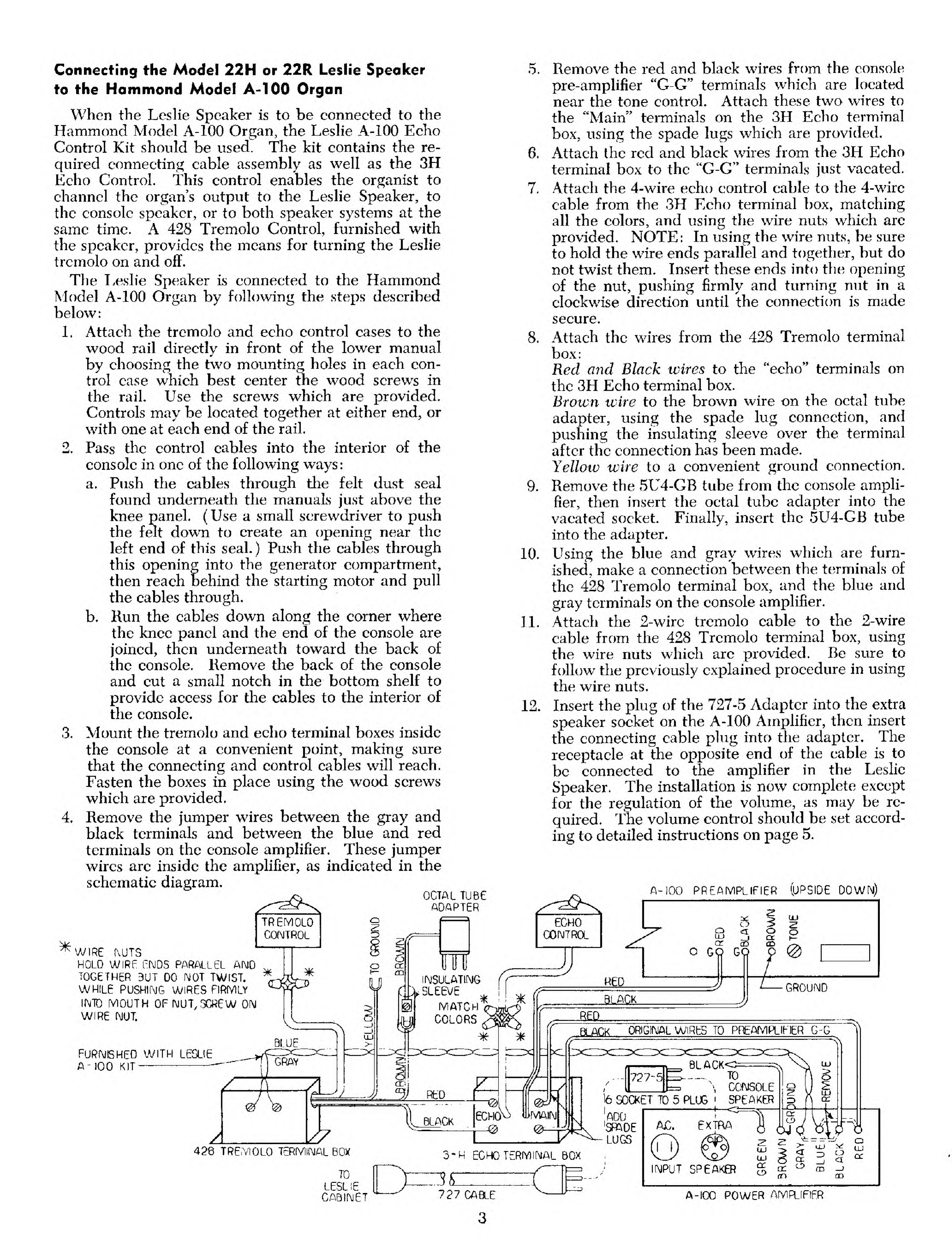
Connecting the Model 22H or 22Rto the Hammond
Spinet, Models L-100, M-l, M-2, M-3, or M-100
When the Leslie Speaker is to be connected to any
of the Hammond Spinet model organs, the Leslie 3-M
Echo Control Kit should be used. This kit contains
the needed connecting cable —in this case a30-foot
length of cable with appropriate connectors installed
at both ends. Also included in the kit is the switch
with associated equipment for the Echo Control, a
device that permits the organist to use either the
Leslie or the console speaker, or to use both speakers
at the same time. A428 Tremolo Control, furnished
with the speaker, provides the means for turning the
Leslie tremolo on and off.
Installation should be made as follows;
1. Attach the tremolo and echo control cases to the
wood rail directly in front of the lower manual
by choosing the two mounting holes in each con-
trol case which best center the wood screws in the
rail. Use the screws which are provided. Controls
may be located together at either end, or with one
at each end of the rail.
2. Pass the control cables into the interior of the con-
sole in one of the following ways
:
a. Push the cables through the felt dust seal found
underneath the manuals just above the knee
panel. (Use asmall screwdriver to push the felt
down to create an opening near the left end of
this seal.) Push the cables through this opening.
b. Run the cables down along the corner where
the knee panel and the end of the console join,
then underneath to the back of the console.
Bring the cables into the console from the rear.
3. Mount the tremolo and echo terminal boxes inside
the console at aconvenient point, making sure that
the connecting and control cables will reach.
Fasten the boxes in place using the wood screws
which are provided.
1

4. Connect the wiring exactly as shown in the follow-
ing diagrams. NOTE: In using the wire nuts be
sure to hold the wire ends parallel and together,
but do not twist them. Insert these ends into the
opening of the nut, pushing firmly and turning nut
in aclockwise direction until the connection is
made secure.
5. Secure the external speaker cable at the lower right
(treble) corner of the console, using the clamp
which is supplied. When all the indicated con-
nections have been made, the installation is com-
plete except for possible regulation of the volume
setting. This should be done, as needed, according
to the instruction given on page 5.
MODELS M-1, M-2, M-100, L-100 CONSOLE INSTALLATION
ECHO
CONTROL
CONNECT THIS BLACK WIRE TO
AMPLIFIER GROUND SCREW ON:
MCONSOLES WITH StRIAL
NUMBERS 8EL0W 3000
LEAVE THIS BLACK WIRE
DISCONNECTED AINSULATE
IT WITH TAPE ON:
M&U-2 C0NS0LL5 WITH
SERIAL NUMBERS ABOVE
3GGG
L-1CG CONSOLES
M-100 CONSOLES
BE SURE TO USE ALL
INSULATING SLEEVES
0R& WIRES FROM
VOICE COIL* TERMS
TREMOLO
CONTROL
MODEL M-3 CONSOLE INSTALLATION
IF TREMOLO CONTROL IS NOT
TO BE INSTALLED, CONNECT THESE
RED AND BLACK WIRES DIRECTLY TO
SCREW TERMINALS ON ECHO BOX.
CABLE AND CONNECTOR (6 POLE)
FOR EXTERNAL SPEAKER
2Z
2
CONNECT UNDER CONVENIENT LESUE ^ADAPTER
6M0. SCREW ON AMR IPLUG INTO AMP.
N^W, socket
L3f
BROWN WIRE NOT USED
CUT SPADE LUGS ON GRY4BLU
WIRES AND SOLDER AS SHOWN
CONSOLE
PREAMP
REI fiLK
®®
ECHO MATCH
COLORS
BRWW
CONNECT THIS BLACK VI RE
TO AMPLIFIER GROUND
SCREV OH
:
M-3 CONSOLES BELOW 107700
WITH AMPLIFIER CODED G,H,
or I
LEAVE THIS BLACK WIRE
DISCONNECTED AINSULATE
WITH TAPE ONi
M-3 CONS0UES SERIAL 4B000
hABOVE WITH AMPLIFIERS
CODED A^C.D.E, &F. (UN-
CODED AMP. DENOTES CODE A
'
M-3 CONSOLES SERIAL 107700
&ABOVE WITH AMPLIFIERS
COOED JAABOVE
ORGAN
CONSOLE
SPEAKER
3M-2 ADAPTER
INCLUDED IN KIT
BE SUftE TO USE
ALL INSULATING SLEEVES
TO SPEAKER SOCKET
ON AMPLIFIER
2

Connecting the Model 22H or 22R Leslie Speaker
to the Hammond Model A-100 Organ
When the Leslie Speaker is to be connected to the
Hammond Model A-100 Organ, the Leslie A-100 Echo
Control Kit should be used. The kit contains the re-
quired connecting cable assembly as well as the 3H
Echo Control. This control enables the organist to
channel the organ's output to the Leslie Speaker, to
the console speaker, or to both speaker systems at the
same time. A428 Tremolo Control, furnished with
the speaker, provides the means for turning the Leslie
tremolo on and off.
The Leslie Speaker is connected to the Hammond
Model A-100 Organ by following the steps described
below:
1. Attach the tremolo and echo control cases to the
wood rail directly in front of the lower manual
by choosing the two mounting holes in each con-
trol case which best center the wood screws in
the rail. Use the screws which are provided.
Controls may be located together at either end, or
with one at each end of the rail,
2. Pass the control cables into the interior of the
console in one of the following ways:
a. Push the cables through the felt dust seal
found underneath the manuals just above the
knee panel, (Use asmall screwdriver to push
the felt down to create an opening near the
left end of this seal.) Push the cables through
this opening into the generator compartment,
then reach behind the starting motor and pull
the cables through.
b. Kun the cables down along the corner where
the knee panel and the end of the console are
joined, then underneath toward the back of
the console. Remove the back of the console
and cut asmall notch in the bottom shelf to
provide access for the cables to the interior of
the console.
3. Mount the tremolo and echo terminal boxes inside
the console at aconvenient point, making sure
that the connecting and control cables will reach.
Fasten the boxes in place using the wood screws
which are provided.
4. Remove the jumper wires between the gray and
black terminals and between the blue and red
terminals on the console amplifier. These jumper
wires arc inside the amplifier, as indicated in the
schematic diagram.
a.
6.
7.
8.
9,
10,
11
12.
Remove the red and black wires from the console
pre-amplifier "G-G" terminals which are located
near the tone control. Attach these two wires to
the "Main" terminals on the 3H Echo terminal
box, using the spade lugs which are provided.
Attach the red and black wires from the 3H Echo
terminal box to the "G-G" terminals just vacated.
Attach the 4-wire echo control cable to the 4-wirc
cable from the 3H Echo terminal box, matching
all the colors, and using the wire nuts which arc
provided. NOTE: In using the wire nuts, be sure
to hold the wire ends parallel and together, but do
not twist them. Insert these ends into the opening
of the nut, pushing firmly and turning nut in a
clockwise direction until the connection is made
secure.
Attach the wires from the 428 Tremolo terminal
box:
Red and Black wires to the "echo" terminals on
the 3H Echo terminal box.
Brown wire to the brown wire on the octal tube
adapter, using the spade lug connection, and
pushing the insulating sleeve over the terminal
after the connection has been made.
Yellow wire to aconvenient ground connection.
Remove the 5U4-GB tube from the console ampli-
fier, then insert the octal tube adapter into the
vacated socket. Finally, insert the 5U4-GB tube
into the adapter.
Using the blue and gray wires which are furn-
ished, make aconnection between the terminals of
the 428 Tremolo terminal box, and the blue and
gray terminals on the console amplifier.
Attach the 2-wirc tremolo cable to the 2-wire
cable from the 428 Tremolo terminal box, using
the wire nuts which arc provided. Be sure to
follow the previously explained procedure in using
the wire nuts.
Insert the plug of the 727-5 Adapter into the extra
speaker socket on the A-100 Amplifier, then insert
the connecting cable plug into the adapter. The
receptacle at the opposite end of the cable is to
be connected to the amplifier in the Leslie
Speaker. The installation is now complete except
for the regulation of the volume, as may be re-
quired. The volume control should be set accord-
ing to detailed instructions on page 5.
OCTAL TUBE
ADAPTER
TREMOLO
CONTROL
WIRE MJTS
HOLD WIRE ENDS PARALLEL AND
TOGETHER 9UT 00 NOT TWIST.
WHILE PUSHING WIRES FIRMLY
IfMTO MOUTH OF NUT, SCREW ON
WIRE NUT.
o
u
FURNISHED WITH LESLIE
A- 100 KIT —
-
A
INSULATING
SLEEVE
MATCH
COLORS
A-100 PREAMPLIFIER (UPSIDE D0WM)
RED
O
o
GO
o
CD
GO
BLACK GROUND
BLACK
1
khov
K0RIG1IMAL WIRES TO PREAMPLIFIER G-G
428 TREMOLO TERMINAL 60/ o-H ECHO TERMINAL BOX
TO
LESLIE
CABINET 727 CABLE
D-
-
6
o
(JJ
NPUT SPEAKER
A-100 POWER AMPLIFIER
3

Connecting the Model 22H or 22R
Leslie Speaker to Hammond Models
Without Self-contained Speakers
For Hammond Models A, B, C, D, E, BV, CV, B-2,
C-2, RT-2, B-3, C-3, RT-3, the connection is made
between the organ console and the Leslie Speaker by
means of the regular connecting cable which is furn-
ished with the Hammond console. A428 Tremolo
Control, furnished with the speaker, provides the
means for turning the Leslie tremolo on and off.
The Leslie Speaker is connected to any of the above-
named Hammond models by use of the following pro-
cedures :
1. Attach the tremolo control case to the wood rail
in front of the lower manual, choosing the two
mounting holes in the case which best center the
wood screws in the rail. Use the screws which are
provided. The Tremolo Control may be located at
either end, although the location at the left end,
directly in front of the pre-set keys, is generally
preferred.
2. Pass the control cable into the interior of the con-
sole in one of the following ways
:
a. Push the cable through the felt dust seal found
underneath the manuals just above the knee
panel. (Use asmall screwdriver to push the felt
down in order to create an opening near the left
end of this seal.) Push the cable through this
opening into the generator compartment, then
reach behind the starting motor and pull the
cable through.
b. Run the cable down along the corner where the
knee panel and the end of the console are
joined, then underneath toward the back of the
console. Remove the back of the console, and
cut asmall notch in the bottom shelf to provide
access for the cable to the interior of the con-
sole.
3. Mount the tremolo terminal box inside the organ
console at aconvenient point, making sure that the
connecting and control cables will reach. Fasten
the box in place using the wood screws which are
provided.
4. Connect the two-wire cable from the tremolo con-
trol to the two-wire cable from the tremolo terminal
box, using the wire nuts which are provided.
IMPORTANT: When using wire nuts be sure to
hold the wire ends parallel and together but do not
twist them. Insert these ends into the opening of
the nut, pushing firmly and turning nut in aclock-
wise direction until the connection is securely
made.
5. Remove the wires from the "G-G" terminals on the
pre-amplifier, and connect them to the screw term-
inals of the terminal box. NOTE: In the case of
Hammond models B-3, C-3, and RT-3 all con-
nections at the pre-amplifier are solder-type con-
nections.
6. Attach the red and black wires from the terminal
box to the "G-G" terminals on the pre-amplifier
which were vacated in step 5.
7. Attach the yellow wire from the terminal box to
any convenient ground screw.
8. The brown ivire from the terminal box is to be con-
nected on the basis of the Hammond model in-
volved:
Models A, B, C, D, E, BV, and CV only:
Attach to the pre-amplifier B-j- terminal along
with the wire (to the cable outlet box) already
connected there.
Models B-2, C-2, and B.T-2 only:
Attach to the brown wire on the Octal Tube
Adapter (Part No. 428-9) which is furnished as a
part of the 428 kit. Once the connection is made
push the plastic insulating sleeve over the terminal.
Remove the 6X5 tube from its socket on the pre-
amplifier chassis, plug the adapter into this socket,
and the 6X5 tube into the socket on the adapter.
Models B-3, C-3, and RT-3:
Attach to the brown wire on the 7-pin adapter
(Part No. 428-8) which is furnished as apart of
the 428 kit. Once the connection is made push the
plastic insulating sleeve over the terminal. Remove
the 6X4 tube from its socket on the pre-amplifier
chassis, plug the adapter into this socket, and the
6X4 tube into the socket on the adapter.
9. Complete the installation by connecting console
and Leslie Speaker, using the cable which is sup-
plied with the Hammond console. The plug at one
end of the cable is to be connected to the socket on
the outlet box in the console; the receptacle at the
other end of the cable plugs into the amplifier on
the Leslie Speaker. The installation is now com-
plete except for the regulation of the volume, as
may be required. The volume control should be
set according to detailed instructions on page 5.
TREMOLD
CONTROL
ATERMINAL
BOX
MOLD WIRE: ENDS
PARALLEL AMD
TOGETHER BUT DO
NOT TWIST. WHILE
PUSHING WIRE
FIRMLY INTO MOUTH
OF NUT, SCREW ON
WIRE NUT.
TYPE 2TREMOLO CONTROL
INSTALLATION IN CONSOLE
Y7
ORIS, WlttS
FROM GS
PREAMP
TERMINALS
UJ
O
o
o
o
5
cr
LESLIE 6* ADAPTER TO BE INSERTED BETWEEN
INDICATED TUBE AND ITS AMPLIFIER SOCKET
6X5
6PIN
B2,C2, RT2
EH
63 C3
RT3
ON MODELS B3. C3. RT3
LESLIE EQUIPMENT WIRES ARE
SOLDERED TO PREAMP TERMINALS.
OTHER MODELS USE LUG CONNECTORS
UNDER SCREW TERMINALS-
A. BX. D.E, BV. CV
%~1
GCKSOLE PREAMP.
AC &* GND G6
REMOVE ONIT WIRES FROM C- TERMS. OH PREAMP,
BROWN 4

VOLUME CONTROL SETTING
The Leslie amplifier is designed purposely to have
more gain than is normally required. Thus, abroad
volume range is available. Volume should be adjusted
on the basis of the console signal output as well as
for the particular acoustic environment.
The volume level should be set on the basis of
maximum demand, avoiding distortion or overload:
1. Using afull registration, that is, with one set of
manual drawbars and both pedal drawbars pulled
out to position eight, play apedal note and afull
chord, with the Swell Pedal fully "open".
2. Advance the volume control on the Leslie amplifier
from aminimum position up to apoint where
some distortion can be heard.
3. Back off the volume control setting just far enough
to eliminate all the distortion. This then is the
correct setting for maximum undistorted loudness,
and no further adjustment will have to be made.
CAUTION:Distortion, if continuous, can ser-
iously damage speaker components.
THE LESLIE TREMOLO
One of the unique aspects of Leslie Speaker design
is the method for producing tremolo, or tremulant.
Two rotary elements within the Leslie cabinet project
the sound afull 360 degrees in amanner which results
in arealistic acoustic tremolo. This patented system
adds important musical values to the tone of the
Hammond Organ, greatly enhancing its performance.
Tremolo Control
Tremolo in the Leslie Speaker is controlled by turn-
ing the power for the tremolo driving motors on and
off. This is accomplished by means of arelay which is
built into the Leslie amplifier. The two motors plug
into AC outlets located on the amplifier.
It will be noted that there are actually three AC
outlets, located together on the amplifier. However,
only two of the outlets are under on/off control.
The third outlet, located nearest to the volume control,
is not affected by the relay, but instead supplies power
whenever the organ and speaker are turned on. (Use
of this outlet will be explained in the section on
special tremolo effects.) The Leslie Speaker, as it is
shipped from the factory, has the two motors plugged
into the two controlled outlets.
Tremolo Rotor Cycling
When the Leslie speaker is first turned on, the
rotors which are plugged into the controlled sockets
will rotate for approximately 10 seconds and then will
stop. If the Leslie tremolo switch is "on" the rotors
will immediately start again, and will rotate con-
tinuously, so long as the switch remains "on".
This initial rotor cycling is completely normal and
occurs only during the warm-up period. After this
warm-up completely normal on-off control will be in
effect.
Special Tremolo Effects
Some intriguing musical possibilities result from
having the Leslie tremolo under only partial on/off
control. In this alternative arrangement the lower
(bass) rotor is kept constantly in motion, while the
upper (treble) rotor is controlled independently by
the Leslie tremolo on/off switch. To accomplish this
the power plug from the lower driving motor is
plugged into the third AC outlet previously mentioned.
This outlet, located nearest to the volume control, is
not affected by the Tremolo switch. It supplies power
to the driving motor continuously while the organ is in
operation.
The uncontrolled outlet in the 22R cabinet will be
used whenever this cabinet is equipped with Rever-
beration kit. Thus, when the lower rotor is to be
kept constantly in motion, this outlet should be
supplied with acube tap in order to accommodate
plugs from both the reverberation amplifier and the
lower tremulant rotor.
The unusual effects that can be obtained from this
partial tremolo control arrangement become apparent
when the Leslie tremolo switch is in "off" position.
The upper tremolo rotor (treble) will remain station-
ary while the lower (bass) rotor will continue to turn.
Through choice of registration and playing range,
some effects of considerable contrast may be obtained.
For example, notes played in the top two octaves
of the keyboard, using abrilliant registration such as
Strings, will be channeled mainly through the treble
rotor. With the tremolo "off" this rotor will not be
in motion, hence these notes will have practically no
tremolo. If at the same time (still with tremolo "off")
notes are played in the lowest three octaves of the
other manual, and using abland registration such as
"Tibia", the sound will be heard mainly through the
bass rotor which is revolving and which will thus pro-
duce afull tremulant. The "solo" part may be played
on cither keyboard, with the "accompaniment" on the
other. Due to the contrasting tremolo treatment
which is given to the two individual playing ranges,
with tremolo "off", the tonal difference between
"solo" and "accompaniment" parts is quite substantial.
Utilization of these special tremolo possibilities will
further be influenced by the vibrato system of the
particular console. Where the instrument is equipped
with electronic vibrato, the vibrato control knob
should be set at Number 1. If the vibrato is controlled
separately for the two manuals many combinations of
acoustical tremulant and electronic vibrato become
possible. Areasonable amount of experimentation
here will reveal many interesting musical possibilities.
Early model consoles were equipped with an ampli-
tude-type tremulant, and in many cases with achorus
generator as well. Both these devices alter the organ s
signal in such away as to make it incompatible with
the Leslie tremulant. Hence, on these early Hammond
consoles neither the tremulant nor the chorus gen-
erator system should be operated at the same time
that the Leslie tremulant is being used.
On Series 3consoles which are equipped with the
Hammond Percussion, the Leslie Speaker makes pos-
sible many interesting tonal combinations. Since the
electronic vibrato is not applied to the percussion out-
put, the only tremulant will be supplied by the Leslie.
The Leslie tremulant may be turned off for those
effects that are best without tremulant, or it may be
used to provide tremulant for such interesting effects
as the "Vibra-harp". Again, reasonable experimenta-
tion with the combination of percussion and Leslie
will result in the discovery of agreat many usable
new sounds.
5

CONNECTING CABLES
The "standard" type speaker-connecting cable, as
supplied bv Electro Music, contains six conductors.
Current models of lx>th the Hammond Orgsm and the
Ix^Iic Speaker actually use only five of the six con-
ductors in this cable/ However, all six conductors
are used with early consoles and speakers. Since these
units continue to be used in installations it seemed
advisable to standardize on cable which would Ik*
adequate for all installation requirements. Adaptation
to the individual speaker and/or organ model is then
amatter of selecting the proper terminal connectors,
as explained in the chart.
The ^conductor connecting cable is supplied in
standard 30-foot lengths complete with plugs and/or
connector terminals.
The cable with 6-pole connectors at both ends b
Leslie Ptart No. 727.
The cable with aplug at one end and "spade-lug*
connector terminals at the other end is I-eslte Part
No.3M-l«
To span distances between console and speaker of
more than 30 feet, the cable from the console may be
supplemented bv one or more 727 cable assemblie s
connected together in series, used as extensions.
In certain installation* ;i specific length of cable
other than 30 feet is required. In such cases bulk
cable should be ordered, along with the necessary
connectors, as Specified in the rents list. (Note: The
spade lugs should Ik? obtained from alocal radio parts
supplier.) lit attaching tin* cable tn the connectors or
to the "spade-lug" connector terminals be sure to
follow the color coding as shown in the cable chart
below. Special care should he given to the handling
of all connections involving AC.
DESCRIPTION
727 CABLE ,COVPtfTC
(INCLUDED IH A-100 KIT)
3W-I CABLE,- COMPLETE
(INCLUDED IN 3U KIT)
721-1 WU CABU tSPCCIFY LEKCTKJ
727*3 SOClCtT (e-CONUCT) AND C4f
727-4 PLUS (5-POU) AND CAP
727-1 BUU CABLE tSPCCIFY LERGTH)
MECHO CONTROL KIT INCLUDES:
727-3 SOCKET AMD CAP
SPADE LUGS
ASSEMBLY DETAIL USAGE
EARLY CONSOLE TO SPEAKER
EXTENSION -rROy CONSOLE
CABLE TO SPEAJCER
EXTENSION •fROM SPCACER
CABU TO ANOTHER SPEAKER
CURRENT HAifttiNO CONSOLE TO
CURRENT LESLIE SPEAKER
CURRENT CONSOLE TO
ICAIM SPEAKER
CURRENT CONSOLE TO
ECHO SPEAKER
SPEAKER TO SPEAKER
CONSOLE TO ECHO SPEAKER
RECOMMENDED
PERIODIC MAINTENANCE
The Leslie Speaker is carefully engineered for
durahilitv and minimum service. Periodic lubrication
and atew simple checks will result in efficient
operation.
Oiling
Oil the two tremulant motors bv placing 20 to 30
drops of the oil which is furnished (or sewing machine
oil) in each of the oil tubes at the back of tlie cabinet.
The motors should be oiled every six months for
normal usage, every three months for commercial
upper tremulant rotor should be oiled every
year under normal operating conditions, every six
months if in commercial usage. The oil hole is found
at the center of the hakelite tremulant assembly, and
is clearly marked. Place about five drops of oil in the
hole, allowing it to drop slowly so as to avoid over-
flow at the opening. Be very careful to prevent oil
from getting onto pulley grooves or driving belt.
Belts
For average service belts usually last several years.
However, since frayed or badly worn belts can cause
noise, tliey should be examined periodically, and re-
placed as necwary.
Tubes
Check periodically to see that all the tubes on th
amplifier are illuminated, and are functioning properly.
The weakening of tubes with long use is such agradual
process that the resulting sub-standard performance
may not at first be noticed. New tubes, if carefully
checked* will restore the speaker to its original oper-
ating efficiency. For best results it (s recommended
that the tubes be replaced before appreciable de-
terioration has occurred.
6

SPECIAL USES OF THE LESLIE SPEAKER
Broadcasting and Recording
To obtain full rich pipe-organ effects, the organ
should be played at afairly high volume, using alive
studio. The microphone should be placed ten to
fifteen feet away from the Leslie. For asmooth
tremulant, adjust the microphone height so that it is
either above or below the upper speaker louvres in the
cabinet,
Non-Organ Use of the Leslie Speaker
The Leslie Speaker is aproduct of superb quality,
designed solely and expressly for use with electric
organs. It does not function satisfactorily in other
applications. The unique musical characteristic of
the speaker is the result of electrical and acoustical
properties totally different from those found in "high-
fidelity" sound equipment. This specialized concept
upon which the Leslie Speaker is based restricts its
recommended usage to the electric organ.
SHIPPING
The Leslie Speaker may be moved or carried in any
position without special preparation. However, if it
is to be shipped, the cabinet should be in an upright
position, with shipping blocks in place to protect the
motor, rotor, and the power amplifier.
In the case of the 22R, tape should also be used to
hold the upper rotor down securely on its base. The
reverberation unit also should be "locked".
INSTALLATION OF REVERBERATION UNIT
IN THE MODEL 22R LESLIE SPEAKER
The Model 22R Leslie Speaker is functionally the
same as the Model 22H; as shipped from the factory
the 22R may be used in exactly the same way as the
22H. The 22R, however, is designed to receive the
Hammond Reverberation Kit. All mounting holes are
pre-drilled, and are properly located for easy in-
stallation of the major assemblies of the reverberation
device. While it is preferable to install the 6X9 rever-
beration speaker on the right side of the Leslie cabinet
(as viewed from the back), it may be that in the
placement of the Leslie, this side of the cabinet is so
close to the wall as to prevent the sound from radiating
properly. In such cases the 6X9 reverberation speaker
may be mounted in the left side of the cabinet, which
is also supplied with louvres and pre-drilled holes.
Complete installation details are provided for use of
both speaker locations.
The Hammond spinet-type Reverberation Kit, with
console-type speaker, includes all major assemblies as
well as some of the small parts for the installation.
The remainder of the parts are either contained in the
kit of materials supplied with the 22R speaker, or will
be found already in the cabinet. The following parts,
included in the Hammond kit, are to be used in the
installation —other parts may be discarded:
Reverberation amplifier with blue and black line cord
attached.
Reverberation unit with blue and black wires attached.
Reverberation unit guide bracket.
Console-type 6X9 speaker with volume control and
green and black wires attached. (Remove speaker
from the wooden console speaker box.
)
Amplifier shield base (aluminum foil.
)
Two #4 xsheet-metal type screws for guide
bracket.
Six #8 xsheet-metal type screws, for reverberation
unit (2) and for speaker mounting (4).
NOTE: In addition to the usual service tools, the
reverberation installation will also require use
of "stubby" screwdrivers for the regular
slotted-head screws and for the Phillips head
screws.
Installation of the Hammond Reverberation device
is to be made as described below. It is necessary that
all three back panels be removed in order to provide
unrestricted access to the interior of the cabinet.
Specific directions (left, right) will be oriented on the
basis of viewing the cabinet from the back.
1. Remove the four 10/24 x7
/8"machine screws from
the amplifier mounting holes in the left-hand side
of the upper shelf. Place the aluminum foil shield
on this shelf, aligning the holes in the shield with
the mounting holes in the shelf. Place the two
felt strips at the ends of the shield, again aligning
the holes in the felt with the mounting holes in
the shelf. Mount the reverberation amplifier over
the shield and the felts, with the terminal strip
facing the horn assembly. Fasten the amplifier in
place using the previously removed machine
screws. Fasten at three points, but not at the
right rear corner of the amplifier chassis. The
bracket for the volume control is to be installed
there, as will be explained in step number 8.
2. Take out right-hand wood speaker-cover box by
removing the wing nut and angle bracket which
hold it in place.
3. Mount the reverberation unit guide bracket as-
sembly on the shelf to the right of the bass
speaker, using the pre-drilled mounting holes.
Be sure that the springs in the assembly face away
from the side of the cabinet. Fasten the assembly
in place with two of the #4 x%" screws.
4. Insert two of the #8 x%" screws into the pre-
drilled holes midway in the right side panel of
the cabinet, and tighten them down to approxi-
mately 3/32" from the surface.
5. Insert the vertical channel of the reverberation
unit between the springs of the guide bracket,
then hang unit on the screws which were installed
in step 4. Check to be sure that mounting slots of
the reverberation unit are properly seated over the
mounting screws and that the vertical channel is
still in place between the springs of the guide
bracket. Finally, tighten the mounting screws.
6. After the 6x9 speaker has been removed from the
wooden console speaker box, it should be pre-
pared as follows for installation in the Leslie
cabinet
:
a. Cut the green and black wires leading to the
speaker volume control about 2l
/
zinches from
the speaker. Strip about l
/2inch of insulation
from the ends of the two wires leading to the
speaker.
7

n
i.
8.
9,
10,
11
b. Using wire nuts, connect the green and black
jumper wires (furnished in the Leslie kit) to
the two wires from the speaker. Speaker is
now ready for mounting, (The volume control
assembly previously cut off will be used later
in the installation.) IMPORTANT: When
using wire nuts be sure to hold the wire ends
parallel and together but do not twist them.
Insert these ends into the opening of the nut,
pushing firmly and turning nut in aclockwise
direction until the connection is securely made.
To mount the 6x9 reverberation speaker on the
RIGHT-HAND side, simply locate it properly
over the pre-drilled mounting holes behind the
louvres on the right-hand side. Fasten in place
using four of the #8 x%" screws. Replace the
wood speaker-cover box, threading the green and
black speaker wires out through the slot in the
box. Secure box in place, using the mounting
bracket and wing nut removed previously. Should
it be desirable to mount the reverberation speaker
on the LEFT-HAND side, these steps should be
followed:
a. Remove the bracket and the long screw which
are used to secure the speaker-cover box in
position, and remount these in the left side of
the cabinet, using the pre-drilled holes.
b. Remove the wood cover behind the louvres in
the left side of the cabinet, and install on the
right side,
c. Remove the other cover from the left-side
panel and place it over the two holes in the
right side of the upper shelf, aligning the cover
with the pre-drilled holes in the shelf. Fasten
the cover in place with screws.
d. Mount the 6x9 speaker behind louvres on left
side of cabinet, using pre-drilled holes and
fastening in place with four of the #8 x%"
screws.
e. Replace the wood speaker-cover box, thread-
ing the green and black speaker wires out
through the slot in the box. Secure box in
place using the mounting bracket and wing
nut previously removed.
Mount the speaker volume control and wire as-
sembly (removed in step 6) on the metal bracket
which is furnished. Locate the control and
bracket assembly at right rear corner of rever-
beration amplifier, placing bracket base between
felt and foil. Use 10/24 x%" screw to secure both
the amplifier and the bracket.
Using wire nuts, connect the green and black
wires from the volume control to the green and
black (jumper) wires from the 6x9 speaker.
Attach the green and black wires (from the
volume control, and equipped with spade lugs)
to the "speaker" terminals on the reverberation
amplifier.
Connect the spade lugs on the ends of the black
and blue jumper assembly (furnished in Leslie
kit) to the driver terminals on the reverberation
amplifier. Connect the opposite ends of these
jumper wires to the black and blue input wires of
the reverberation unit, covering these connections
with the plastic sleeving which is also furnished.
12. Connect the shielded extension cable (from Leslie
kit) between the output wires of the reverberation
unit and the reverberation amplifier,
13. Connect the short brown wire (from Leslie kit)
across the "Switch" terminals on the reverberation
amplifier.
14. Remove the insulation covering the spade lugs at
ends of the red and black Leslie amplifier output
wires. (These wires come from the 2-polc con-
nector assembly located on the left side of the
bass speaker shelf. )Connect these wires, using
the spade lugs, to the "Signal Input" terminals on
the reverberation amplifier.
15. Attach the AC plug (from Leslie kit) to the blue
and black wires from the reverberation amplifier.
Plug into an AC socket on the Leslie amplifier,
using the socket which is nearest to the volume
control knob.
16. Dress all jumper wires together near the left side
of the bass speaker shelf. Snap the plastic cable
clip (from Leslie kit) around these wires and
fasten to the left side of the cabinet, using the
#8 xYi" screw. Thus secured, the wires cannot
vibrate and create noise.
17. Replace all three backs on the Leslie cabinet.
Unlock the reverberation unit by turning the lock
rod which is accessible under the metal cover
found near the right side of the center back cover
panel of the Leslie. To UNLOCK, turn the rod
Kturn to the right, bringing the slot of the rod
to avertical position. (To LOCK the reverber-
ation unit, the rod is to be rotated ^turn to the
left, so that the slot is horizontal. The unit
should always be LOCKED whenever the speaker
is being moved.)
18. Set the volume control for the 6x9 speaker so as
to provide the desired amount of reverberated
sound. The installation is now complete.
MULTIPLE SPEAKER INSTALLATIONS
When aparticular installation requires greater
volume than can be obtained without distortion from
asingle Leslie Speaker, additional units may be added.
Additional speakers bring an improvement in the
musical quality as well as an increase in the overall
volume. Adding speakers is like adding chests of
pipes in apipe organ: the sound is distributed over a
broad area. This effect of "bigness" is most pro-
nounced when the speakers in amultiple installation
are separated from each other by fifteen to twenty
feet. Also, the selection of adifferent pulley groove
(upper motor) for each speaker provides contrasting
tremolo effects, further enhancing the pipe organ
effect.
Amultiple speaker installation may include any
type of Hammond tone cabinet, and early model Leslie
Speakers along with the current Leslie models. Where
reverberation is involved special handling is required.
Although it is technically possible to pass the reverber-
ated Hammond signal through the Leslie Speaker, it is
not always the desirable course; in addition, the in-
stallation becomes extremely complicated. The prefer-
able course, where reverberation is desired, is to use
the Leslie Model 22R Speaker.
8

One of the principle differences between current
and early Leslie models is in the tremolo control
circuitry. Thus, where earlier Leslies are used in an
installation, special procedures must be followed, as
described on pages 12 and 13.
Tremolo, in amultiple speaker installation, may be
controlled for all the current model Leslie Speakers,
by asingle on-off tremolo control switch. However,
the use of two tremolo controls makes possible the
independent control of the two Leslie Speakers or two
groups of Leslies that may he used in the installation.
Power Requirements —Use of the 5A Relay
Although any number of speakers may be used to-
gether in an installation, the AC power requirements
must.be handled in such away as to avoid overloading
the console circuits. These circuits will quite easily
power one Leslie or Hammond speaker, but for each
additional speaker it is desirable to provide an outside
source of power. To accomplish this, and at the same
time to maintain complete on/off control through the
console power switch, the Leslie 5A Power Relay
should be used.
One of the 5A Power Relavs should be attached to
the input plug on each of the extra speakers. The
connector cable plugs into the 6-pole plug on the relay
and the AG cord from the relay is to be connected to
aconvenient electrical outlet.
Through use of the 5A Power Relay the console
circuits are not overloaded, although power for all the
speakers is turned on or off by the console switch.
5A
POWER RELAY
TO 117 VAC
RELAY IS ENERGIZED
WHEN CONSOLE POWER
Wife; 15 ™NED 0H -
Volume Control Settings on Multiple Speakers
In amultiple installation, the volume control for
each one of the speakers should be set according to the
instructions given previously. (See page 5). If the
maximum levels thus obtained result in too much over-
all loudness further adjustments should be made.
It is most important that abalance be maintained
between the several speakers that may be used in an
installation. Each speaker should make approximately
the same contribution to the total sound. No speaker
should be allowed to overpower the others. Time
spent in achieving the "right" adjustment for each
speaker will greatly improve the final musical results.
Pedal Loudness
When two or more speakers are being used together
and are adjacent, they should be phased so that
with individual pedal notes the speakers reinforce
rather than cancel each other.
If improper phasing is suspected, try reversing the
red and black output leads in the two-pole plug at the
amplifier of one of the speakers. If louder pedal out-
put results from this change it should be made
permanent. However, if the pedal level is instead
reduced, the original connection should be restored,
and it may safely be concluded that the problem is
acoustical rather than one of phasing.
Connecting Cables —Multiple Installations
Cable, when supplied with aHammond console, is
the 5-conductor type, with a5-pole plug at one end
for the console connection, and a6-contact socket at
the other end of the cable for the speaker connection.
This cable may be used satisfactorily for any Ham-
mond cabinets and for current models of the Leslie
Speaker.
Early model Leslie Speakers and/or early model
Hammond Organs necessitate use of 6-conductor con-
necting cables. This standard Leslie cable is available
in bulk quantity (Leslie Part No. 727-1) or in 30-foot
lengths complete with 6-pole connectors at each end
(Leslie Part No. 727). The 6-conductor cable may be
used throughout an installation, for the Hammond
speakers and for all models of the Leslie Speaker.
Where only 5conductors are required a5-contact
socket is provided for the cable connection. The 6-pole
plug on the end of the connecting cable must then be
fitted with a5-to-6 Adapter (Leslie Part No. 727-5) to
permit the connection to be made.
Detailed information for handling specific cable
connections, and for preparing cables, will be found
in the chart on page 6.
Early Model Leslie Speakers
Tremolo rotors in the early model Leslie Speakers
are started and stopped by acontrol current which is
carried over the sixth (B-f-) wire in the connecting
cable. Tremolo control in the current model Leslie
Speakers is accomplished by means of aDC voltage
which is superimposed on the signal lines. This is
known as the "Type 2Tremolo Control system".
Special circuitry in current Leslie amplifiers uses
this superimposed DC voltage for control purposes,
yet isolates it from the signal input grids. Amplifiers
in early model Leslie Speakers and in Hammond tone
cabinets do not use this voltage, nor do they have the
necessary isolation circuitry.
Early Leslie Speakers are those with serial numbers
below 5200, Some of the 31 series Leslie Speakers are
in this category. However, most of the 31 series, as
well as all of the 21H, and the present 22H and 22R
models, are all categorized as "current" models. They
all utilize the Type 2Tremolo Control system, and are
easily recognized as current models since the serial
numbers are above 5200.
Tremolo control in installations involving early
model Leslie Speakers must be given special handling.
The DC voltage used for on/off control in the current
model Leslie Speakers will not provide the same con-
trol in the early Leslie. In fact, the DC voltage must
he completely isolated from the early Leslie, or hum,
low output, and distortion will result. Isolation of the
DC control voltage from the early Leslie is ac-
complished through use of the Type 2Adapter.
9

The Type 2Adapter prevents the DC control voltage
from reaching the early model Leslie Speaker ampli-
fier, yet at the same time keeps this voltage available
for additional current model Leslie Speakers, so that
they will have fully controlled tremulant operation.
The adapter doesn't affect amplifier operation in any
way. However, it does change the impedance value
on the amplifier's extra speaker socket. Therefore, any
additional speaker following the adapter must have
its cable connected to the socket on the adapter box,
rather than to the extra speaker socket on the amplifier.
The tremolo rotor operates continuously in any early
Leslie Speakers on which the Type 2Adapter is
used. Where full tremolo control is required for
the early Leslies, the console should be equipped
with a228 Tremolo Control. This would be in ad-
dition to the Type 2Tremolo Control (428) which
would still be required to control the current Leslies.
The Type 2Adapter must be used with earlier
Hammond tone cabinets in all cases where those units
are connected to the channel (Echo or Main) which
is supplied with the DC tremolo control voltage.
However, the Type 2Adapter should not be used
with Hammond tone cabinets Type PR and later. For
these units it is necessary to keep one of the channels
completely free of the DC tremolo control voltage;
by connecting the Hammond tone cabinets to this
channel the need for the Type 2Adapter is eliminated.
Such an installation, illustrated in Figure 2, page 12,
is actually preferable for all Hammond tone cabinets.
However^ it is mandatory for the PR (and later) series,
and is the only satisfactory arrangement for using these
particular tone cabinets in conjunction with current
model Leslie Speakers.
Modification of Early Leslie Speakers
Early Leslie Speakers may be modified and thus
made fully compatible with the current model Leslie
Speakers. The modification must be done at the
Electro Music factory, and since all changes are made
within the amplifier, this is the only part of the Leslie
Speaker that need be sent to the factory.
The Type 2Tremolo Control circuitry which is
installed at the time of modification is functionally
identical to that of the current Leslie models. The
same 428 Tremolo Control kit may be used, and the
Type 2Adapter is no longer necessary. Since the
428 Tremolo Control kit is not automatically supplied
as apart of the modification "package" it should be
ordered separately if required.
MULTIPLE INST
In the following several pages details are given for
the various types of multiple speaker installations.
The techniques for combining current model Leslie
Speakers with early model Leslies and/or Hammond
tone cabinets are fully explained and illustrated.
Finally, several typical installation layouts are pro-
vided, as ameans for summarizing principles which
must be followed in multiple installations:
1. To provide AC power for the second and all ad-
ditional speakers used in an installation, a5A Relay
should be used at the amplifier of all but the first
speaker.
Echo (Speaker Selector) Controls
The use of multiple speakers in an installation not
only results in greater sound volume, but also makes
possible improved sound distribution. To this end,
the several speakers that may be used in an installation
are usually separated from each other by areasonable
distance. Or, where the installation is quite sizeable,
the speakers are arranged together in groups which
are in turn separated from each other.
Since it is usually desirable that the organist be
able to use the speakers selectively, an "Echo Control"
is used to accomplish this purpose. The Echo Control
is in effect aswitching device that permits the
organist to select the speaker or speakers that will be
heard. For the purpose of convenient identification,
the speaker or speakers located nearest to the console
are usually designated as "Main'' speakers. The
speaker or speakers located at apoint more remote
from the console are then referred to as "Echo"
speakers.
Multiple speaker installations normally involve the
larger Hammond consoles —those without any built-
in speaker systems. Where an Echo Control is used
with these Hammond models, it should be the type
3H control. If, for reason of availability, it is desirable
to use some switching mechanism other than the
recommended Leslie 3H Echo Control, the circuitry
must be modified as necessary so that it is identical to
that of the 3H control. (See diagram page 15.)
Multiple installations with Hammond models having
built-in speaker systems will not afford the organist
the complete flexibility of speaker selection as will
be the case with the larger Hammond models. The
former Hammond Models, specifically the Models M
and A-100, employ an Echo Control (types 3M and
A-100, respectively) for the purpose of channeling the
sound either through the console speaker or through
the Leslie Speaker. Additional Leslie or Hammond
speakers may be connected to the first Leslie Speaker,
and wTill be heard simultaneously with it. Since one
position of the Echo Control switch is reserved for
the console speakers the other position will necessarily
activate all the external speakers. Further selective
channeling on these Hammond models with built-in
speakers becomes extremely complicated and there-
fore is not recommended.
DNS IN DETAIL
2. Early model Leslie Speakers and early Hammond
tone cabinets, when connected through the channel
that is affected by the 428 Tremolo Control, must
be connected by means of the Type 2Adapter, so
as to isolate the tremolo control voltage from these
particular units.
3. The Type 2Adapter need not be used with early
model Leslie Speakers and Hammond tone cabi-
nets, providing these speakers are connected to the
channel which does not at any time receive the
tremolo control voltage.
4. Full tremolo control for any early model Leslie
Speakers will result only from the use of the Type
228 Tremolo Control. Otherwise, the early model
Leslie Speakers will produce aconstant tremulant.
10

Installation of the Leslie 3H Echo Control
For Hammond Models: A, B, C, D, E, BV, CV,
B-2, C-2, RT-2, B-3, C-3, and RT-3
1. Attach the echo control case to the wood rail
directly in front of the lower manual, choosing the
two mounting holes in the control case which best
center the wood screws in the rail. Use the screws
which are provided. The echo control may be
mounted at the right end of the rail, or at the left
beside the tremolo control.
2. Mount the echo terminal box inside the generator
compartment near the pre-amplifier.
3. The echo control cable should be passed into the
interior of the console, using the same method as
was chosen for the tremolo control cable. In-
structions for the latter will be found on page 4,
item 2.
4. Provision for attaching the speaker connector cable
should be made in one of two ways
:
a. If an outlet box is provided in the console for
the speaker connection, remove one of the metal
5.
knock-outs and install cither a5-contact socket
if Hammond cable is to be used, or a 6-contact
socket (furnished with the 3H kit) if the Leslie
727 cable assembly is used. (If the outlet box
is already equipped with asecond 5-contact
socket, use of the 727-5 Adapter makes it
possible to attach the 6-pole plug of the Leslie
727 cable assembly.
)
b. If the outlet box method of connection is not
used, the speaker cable may be fed into the
generator compartment through asmall notch
that can be made in the bottom shelf of the
console. In this method, the 3M-1 cable is
recommended for use. The 3M-1 is a30-foot
assembly, complete with the necessary con-
nectors. For cable lengths other than 30 feet,
bulk cable should be used. The needed con-
nectors (6-contact socket and spade lugs) are
regularly included in the 3H Echo Control kit,
Complete the remaining connections for the Echc
Control installation according to the diagram be-
low;
TREMOLO
CONTROL
FIGURE 1
MATCHI.
COLORS C^W^-DRED
BLACK
5
o
tr
Ll_
o
LU
S
LU
cr
CO
LU
cr
LU
a:
CL.
rn NO
OCO
<
8
q: I
cr
<LU
o£3
cc i
o
TWIST
CONNECT TO G-G TERMINALS ON PREAMP
FTREMOLO CONTROL IS NOT INSTALLED
MAIN \\
3H TERMINAL BOX
TWIST-
OUTLET BOX INSTALLATION
SEE PARAGRAPH "A"
NOT SUPPLIED \
\
\
INSULATING SLEEVES
NOT INSTALLED ON
ALTERNATE INSTALLATION
\
\
\
s
\
r\
©3,
6X4*
7PIN
cs
|AC 14
o
LU
cr
3CO
+
©
GND
4
CD
CONSOLE PREAMP TERMINAL STRIP
t
ALTERNATE INSTALLATION USING 3IVH CABLE
SEE PARAGRAPH "8"
GRAY
AC BLUE
AC
YELLOW
GND N.C. 2I
<
I
CD
5
o
TO ECHO SPEAKER
RED BLACK
SIG. SIC
SOCKET
BACK VIEW
WIRE NUTS
HOLD WIRE ENDS PARALLEL AND TOGETHER BUT DO NOT TWIST-
WHILE PUSHING WIRES FIRMLY INTO MOUTH OF NUT.SCREW ON"
WIRE. NUT.
1
1

Special Handling of DC Tremolo Control Voltage
The installation shown in Fig. 1introduces the DC
tremolo control voltage at apoint in the circuit which
causes it to be present in both the Main and the
Echo speaker channels. For this type of installation
it is generally assumed that only the current model
Leslie Speakers will be used in the installation. How-
ever, in those installations where the speaker or
speakers on one of the channels are either Hammond
tone cabinets, or early Leslies, or both, the Tremolo
Control should be installed in adifferent manner.
Since it is desirable to keep the DC tremolo control
voltage out of the channel which includes Hammond
tone cabinets and/or early Leslies, the Tremolo Con-
trol should be connected into the circuit following the
Echo Control, as shown in the installation sketch be-
low. This particular arrangement assumes that the
current model Leslie Speakers will be connected to the
Echo channel, whereas the early Leslie Speakers
and/or any Hammond tone cabinets will be connected
to the Main channel. 7n this tony the Type 2Adapter
need not be used. However, if for any reason it be-
comes necessary to use earlv Leslie Speakers or
Hammond tone cabinets on the Echo channel, the
tremolo control voltage must be isolated through the
use of aType 2Adapter. The Type 2Adapter, when
used, is connected to the amplifier which is to be
isolated from the DC control voltage, the connection
being made at the plug which would otherwise receive
the cable from the console. This cable then plugs into
the Type 2Adapter. (Sec "Early Model ^Leslie
Speakers", page 9.)
FIGURE 2
TREMOLO
C0NTR0L
MATCH
COLORS
STRIP
ALTERNATE INSTALLATION USING >3M-
SEE PARAGRAPH "B" ON PAGE CABLE
GRAY
AC BLUE
AC
YELLOW
GND. 3I
%0
CD
RED BLACK
SIG. SIG.
SOCKET
BACK VIEW
TO ECHO SPEAKER
WIRE NUTS
HOLD WIRE ENDS PARALLEL AND TOGETHER BUT 00 NOT TWIST-
WHILE PUSHING WIRES FIRMLY INTO MOUTH OF NUT, SCREW ON
WIRE NUT.
12

Multiple Tremolo Control
Tremolo for two Leslie Speakers, or for two groups
of Leslie Speakers, may be controlled independently
by the use of two tremolo controls, connected as
shown in the diagram below. Since both these con-
trols are the Tremolo Controls, the DC tremolo con-
trol voltage will be present in both the Echo and
the Main channels. As noted previously, the Type 2
Adapter must be used to isolate this DC tremolo con-
trol voltage from any early model Leslie Speakers or
early Hammond tone cabinets that may be used in
either channel. Hammond tone cabinets, series PR
and later, may not be used in this type installation.
When early model Leslie Speakers are used in an
installation and it is desirable to control the tremulant
on these units, a228 Tremolo Control must be used.
This control may be obtained from Electro Music,
together with complete instructions for its installation.
r
TREMOLO
CONTROL
"ECH0'J
FIGURE 3
ALTERNATE INSTALLATION USING 3M-I CABLE
SEE PARAGRAPH "0* QN PAGE II
GRAY
AG BLUE
AC
YELLOW
GND NC 2I
QC viri
3
o
JLU
TO ECHO SPEAKER
!
RED
SfG BLACK
SIG
iSOCKET
IBACK VIEW
i
*WIRE NUTS
HOLD WIRE ENDS PARALLEL AND TOGETHER BUT DO NOT TWIST.
WHILE PUSHING WIRES FIRMLY INTO MOUTH OF NUT SCREW ON
WIRE NUT.
J
13

GENERAL GUIDE FOR MULTIPLE SPEAKER INSTALLATIONS
KEY TO ACCESSORY ANO CONNECTOR
2A- TYPE 2ADAPTER
5A- LESLIE POWER RELAY
5P- PLUG ,5 POLE
DESIGNATIONS
5S-SOCKET, 5POLE
6S- SOCKET, 6POLE
SLIE -SERIAL BELOW 52(
LESLIE "SER IA LABOVE 52(
(INCLUDES 21 HANO
LATE 31 H)
NTHIS INSTALLATION TREMOLO IN THE
EARLY LESLIE OPERATES CONTINUOUSLY
117 VAC 117 VAC
CONSOLE CURRENT
LESLIE
6EARLY
LESLIE
ORIGINAL CABLE
^
—
HAMMOND
H,HR AND
EARLIER SER-
IES ONLY
=Wi
WITH CONSOLE TO ADDITIONAL SPEAKER
ECHO TREM.
3H 426
NOTE; USE FIG ICONNECTION WHEN MAIN SPEAKER IS CURRENT LESLIE. TREMOLO WILL 8E FULLY CONTROLLED
USE FIG.2 CONNECTION WHEN MAIN SPEAKER IS EARLY LESLIE OR HAMMOND. TREMOLO IN EARLY LESLIE
WILL OPERATE CONTINUOUSLY.
ECHO SPEAKER
CURRENT
LESLIE
7VAC MAIN SPEAKER
TO ADDITIONAL SPEAKER
ORIGINAL CABLE WITH CONSOLE TO ADDITIONAL SPEAKER
ECHO
3H TREM.
428 TREM.
428
SEE FIG. 3
ECHO SPEAKER
CONSOLE CURRENT
LESLIE
17 VAC MAIN SPEAKER
TO ADDITIONAL SPEAKER J)
ORIGINAL CABLE WITH CONSOLE TO ADDITIONAL SPEAKER *0
ECHO
3H TREM
228 TREM
426 SEE FIG, 2. ALSO INSTALLATION INSTRUCTIONS SUPPLIED WITH 228 CONTROL
CONSOLE
7VAC 117 VAC
CURRENT
LESLIE
ECHO SPEAKERS
1EARLY
LESLIE
OR
HAMMOND
ta 5AJs>, m*
117 VAC
6
TO
ADDITIONAL
SPEAKER
MAIN SPEAKERS
EARLY
LESLIE
OR
HAMMOND
W
TO ADDITIONAL SPEAKER
5POLE SOCKET "TO 6POLE PLUG ADAPTER REQUIRED ON SOME 31H LESLIES ORIGINAL CABLE WITH CONSOLE
14

*See Amplifier Schematic on page 23 for 22H Cabinets below Serial 22750, 22R Cabinets below 40900,
or
TYPE 3M ECHO COfNTROL
(3M KIT)
TO VOICE COIl >
TERMINALS RED
CW AMfLlFlEft >
~l
rO 4MAIN
EN5EM&LE
ECHO
_J
TO TYP£ 2
TREMOLO CONTROL
OR
ECHO SPEAKtA
CABLE
TO CONSOLE
SPEAKER YELLOW
VOICE COIL 5>
CONNECT BLACK WIRE (GROUND )AS SHOWN IH
MODEL MINSTALLATION 01ASRAN ON PAGE 2
TYPE 3H ECHO CONTROL
(3H AND A-IOO KITS
)
I—
O
L
o
mi
MAIN
ENSEMBLE
ECHO
J
UJ
o
r
RED
MAIN
SPKR.CA&U
BLAC\
c
SI
3
o
BED
ECHO
SPKft. CABLE
>BLACK
TO PREAMP OR TREMOLO CONTROL
423 TREMOLO CONTROL
6X4
ADAPTER FOR USE
WITH CONSOLE
RECTIFIER
6X5
5
o
CD
DC tt£T MoJl
TO ORGAN PREAMP
G6 TERMINALS
,i:i
isolation
TRANSE
I
TREMOLO
SWITCH
TO
EXTERNAL
SPEAKER
CABLE
TO GROUND
TYPE 2ADAPTER

SERVICING AND TECHNICAL
INFORMATION
ON COMPLETE LESLIE SPEAKER CABINET
Replacement Parts for Servicing
Replacement transformers, filter chokes, and tremolo
relays, should be obtained from the Electro Music
factory. Standard type parts such as rubes, fuses,
sockets, resistors, and condensers, can be obtained
from radio parts supply stores. The detailed parts list
with this manual will give full parts replacement
information.
AMPLIFIER AND ELECTRICAL
Amplifier is removed from cabinet by taking out
the one screw that holds the front end of the amplifier
to the bottom of the cabinet. After the two motor plugs
and speaker plugs are removed, the amplifier may be
withdrawn. When pushing the amplifier back into
place, align the back end of the chassis in approxi-
mate position so that the amplifier guide and hold-
down clamp will engage the amplifier.
Fuse
The amplifier uses areplaceable Slo Bio V/
2amp.
fuse to protect the power supply against most short
circuits. Before replacing ablown fuse, determine the
cause of fuse failure. Do not substitute afuse having
ahigher current rating than that specified.
Screen Voltage Regulation on Power Tubes
This amplifier uses anew and relatively simple regu-
lating circuit to hold the output tubes screens at the
best operating voltage regardless of signal level varia-
tions. The result is maximum efficiency in getting the
greatest useful power output for the total power con-
sumed.
Gas regulator tubes will maintain aconstant voltage
drop regardless of current variations, within rated lim-
its. By proper choice of gas tube relative to the power
supply voltage, aclosely held voltage is made avail-
able for the screens. Parts used and functions are as
follows:
1. 0C3-VR105 Regulator tube provides constant volt-
age reduction in aseries circuit to the output tubes
screens.
2. 470 ohms 1/2 watt resistor—not critical in value.
Acts to suppress possible gas tube oscillations
caused by screen current variations. It also acts as
afuse in case of accidental screen circuit short.
Tremolo Control Malfunctions
Non-operation of the Leslie tremulant can be cor-
rected by checking the following:
1. Make sure the tremolo control is wired into the
circuit exactly as shown in the diagram for the
type installation which is being made.
2. Check the connecting cable for shorts or other con-
ditions which would alter the DC voltage super-
imposed on the signal line. It should be approxi-
mately 100 volts.
3. If anon-Leslie speaker selector (Echo) switch or
Hammond cabinet is included in the hook-up,
make certain the echo switch or cabinet connection
doesn't cause the superimposed DC voltage to be
grounded out.
4. Should none of the above reveal the non-operation
cause, then adetailed check of the Leslie tremolo
circuit components both in the console and Leslie
amplifier should be made against the wiring dia-
grams in this manual.
Operation of the Tremolo Control
The (428) tremolo control circuit superimposes a
DC controlling voltage on the signal line to the speak-
er cabinets. This is used to actuate atube operated
relay circuit for turning power on and off to the
tremulant motors without need of control wires from
the console to the speaker cabinets.
The tremolo control box installed at the console has
aDC isolation transformer in the signal line. Without
affecting the organ generator or amplifier circuits in
any way, apositive voltage can be applied to the
speaker signal line at the transformer center tap. A
10 mfd. condenser at the center tap puts the signal
line at low audio impedance to ground, and yet allows
changes in DC potential.
The relay control tube is one triode of a12AU7.
This triode has the relay coil and acurrent limiting
resistor in its plate circuit. The cathode is connected
to the cathodes of the output tubes and so is about 25
or more volts above ground. With the grid at ground
potential, this cathode potential cuts off the plate cur-
rent flow. With aDC potential on the signal line
greater than the biasing 25 volts, the grid is raised up
to the cathode potential and the triode draws plate
current to operate the relay.
The triode control grid has aone megohm isolating
resistor. This resistor prevents the grid from being
driven positive with respect to cathode, and also pre-
vents any effect on the operation of the audio on the
signal line. Because the resistor also acts as alimiter,
the DC control voltage is not critical and allows cir-
cuit operation over wide variations in B+ and AC
line voltages.
The furnished tube adapters used to obtain the con-
trolling voltage from the organ amplifier, have internal
dropping resistors which protect the power supply in
case of an accidental short circuit.
Distortion
Distorted sound is often caused by atoo high set-
ting of the Leslie volume control. Amplifier gain is
purposely greater than necessary, so low output con-
soles can still provide full sound power output from
the Leslie. Arbitrary setting of this volume control at
maximum will surely result in distortion when the or-
gan sw^ell control is fully opened. Instructions for
properly setting the volume control are given in an
earlier section of the manual.
Brilliance of Sound
Avariation in high frequency output from the Leslie
can be arranged. The amplifier includes a.001 mfd.
capacitor from grid to grid of the balanced input
stage. By changing the value of this capacitor, varia-
tions in brilliance of tone can be obtained
16

To increase brilliance, change the value to about
500 mmfd. or less. To decrease brilliance, shunt addi-
tional capacity across existing capacitor, or replace
with agreater value to obtain desired balance. Do
not change the output transformer primary shunting
condensers.
Voltage Readings
If the amplifier develops difficulties resulting in mal-
function or non-operaton that is not remedied by
tube or electrolytic condenser replacements, the vari-
ous voltages should be measured and compared to the
voltages shown on the circuit diagram. The voltages
indicated were measured with a20,000 ohms per volt
voltmeter, and differences in meter resistance and line
voltage variations as well as parts tolerances should
be kept in mind. If any abnormally high or low volt-
age is noted, it usually indicates adefective part in
the associated circuit.
Transformer Replacement
If the output transformer is replaced, the two plate
leads should be as short as possible and lie close to
the chassis.
Electrolytic Condensers
Practically all modern amplifiers contain electrolytic
condensers. These have adefinite life expectancy, and
must eventually be replaced. The Leslie amplifiers use
the finest electrolytic condensers obtainable, and ex-
perience has shown that many years of trouble free
service can be expected.
In view of the fact that they will eventually wear
our, most of the electrolytic condenser units on the am-
plifier^ are contained in asingle plug-in unit that can
be replaced as easily as a tube. The condenser is a
four section 30-30-30-10 mfd. 475 volt unit.
Tubes
Tubes are acommon source of amplifier difficulties,
although it must be recognized that certain mal-
functions which might at first appear to be caused by
tubes, are actually the result of other conditions.
Checking in atube tester will reveal certain tubes
to be defective. However, replacement is also recom-
mended for tubes which have been in service for a
considerable period of time, as their performance will
have deteriorated and the amplifier will not operate
efficientlv.
Tubes for replacement purposes may be obtained
from alocal source. However, for best operating re-
sults it is recommended that the 6550 power tubes
be replaced as apair, with units obtained from
Electro Music, These tube pairs have been carefully
tested and matched for use in the Leslie Speaker.
Line Voltage
Exceptionally low or high line voltage may cause
difficulties with amplifier operation. If the line voltage
falls below 100 volts, unsatisfactory performance will
result. Low line voltage can be caused by poor con-
tacts in the cable wiring or exceptionally long cable.
Adding the Leslie 5A relay is an easy way to overcome
low line voltage due to long cable.
Electric Brake
When the tremolo control switch is in off position,
braking of the tremulant motors is obtained by having
the control relay apply adirect current to the motors.
During the off time, the direct current flows through
the motors continually. No harm is done because the
current is substantially below normal running ratings.
The DC braking voltage is obtained through afull-
wave rectifier circuit in the primary of the power
transformer. Components and functions are as follows:
1. Silicon diode rectifier (two used)
2, 100 ohm, 3watt resistor
3, ,1 mfd, 400 volt filter condenser
4. Suppressor coil—prevents switching clicks
in speaker.
In the case of 22H cabinets with serial numbers
below 22750 and 22R cabinets with serial numbers be-
low 40900, asomewhat different brake circuitry will be
found. In these units the DC braking voltage is
obtained by means of rectifying and filtering a25 volt
tap on the power transformer primary. The com-
ponents used, and their functions, are as follows:
1. Silicon diode rectifier
2. 200 mfd, 50 volt filter condenser
3. 3ohm limiting resistor—protects silicon diode
rectifier from current surges
4. Suppressor coil—prevents switching clicks in
speaker.
LOUDSPEAKER SYSTEM AND DIVIDING NETWORK
The Leslie uses afull two way system with two
separate speakers. Pedal and midrangc tones are gen-
erated by aheavy duty 15 inch speaker with perma-
nent magnet. Its nominal impedance is 16 ohms.
Upper middle and highest tones are generated by a
compression sound chamber driver unit also using
permanent magnet. Its nominal impedance is 16 ohms.
The 15 inch speaker is mounted in amatched bass
reflex enclosure. It is therefore important that the cabi-
net back is in place and securely fastened. The high
frequency driver is loaded by means of arotary horn.
Only one of the horns in the upper rotor radiates
sound. The other horn dynamically balances the as-
sembly to eliminate vibration. Asmall cotton acoustic
filter is placed in the throat of the horn. It also pre-
vents dust from entering the driver unit. Do not re-
move this filter.
The two specialized range speakers are connected to
the amplifier via atwo half section Mderived fre-
quency dividing network (crossover). This network
electrically separates the bass and treble range output
of the amplifier, and directs the proper signal to each
speaker. The nominal separation occurs at 800 cps.
The impedances used in the loudspeaker system allow
adividing network design of extremely rugged and
electrically stable parts. It is very unlikely that trouble
will ever be experienced with this clement.
Speaker Problems
Because of the extremely strong permanent mag-
netic fields with both speakers, it is inadvisable to
attempt cone replacements or repairs involving dis-
17

assembly. The Electro Music factory will either repair
afaulty unit or supply areplacement.
Should the treble speaker become inoperative for
some reason, emergency operation of the cabinet can
be arranged. Unplug the bass speaker from the divid-
ing network and plug it direct to the amplifier output
socket. There will, of course, be alack in musical
quality until the complete system is restored.
Suspected low output from the dividing network
output can be checked by the same procedure as
above.
MECHANICAL MAINTENANCE
Motor
After several years of typical service, or areason-
ably long period in commercial use, the motors might
accumulate lint and dust. This accumulation interferes
with proper ventilation and oiling. Time invested in
cleaning the motors is well repaid by longer life. The
motors can be removed easily and cleaned with cleans-
ing solvent.
Upper Motor Removal and Replacement
Remove the motor power plug from socket, and
remove the two wing nuts. Then the motor can be
removed from the cabinet, IMPORTANT: The upper
motor must run counterclockwise when viewed from
the top or pulley end. Otherwise, the upper tremulant
rotor will not come up to speed. If the motor is dis-
assembled or another motor substituted, the rotation
should be checked to be sure it is counter-clockwise.
Lower Motor Removal and Replacement
Remove the motor power plug from the amplifier
socket and remove the two wing nuts that hold it to
the shelf. The motor will drop down for removal.
When replacing this motor, first position the belt on
the motor pulley before it is lifted into place onto the
mounting screws. Because the front wing nut controls
the tremulant drive belt tension, this must be adjusted
whenever the motor is replaced. See "Belt Tension
Adjustment" below.
Disassembly and Cleaning
For cleaning purposes, before a motor can be com-
pletely taken apart, the pulley, pulley support ring,
and oil tube assembly must be removed. When remov-
ing the end covers, be sure to note or mark the posi-
tion of the bottom end cover with respect to the lami-
nations. If this should be rotated relative to its original
position, bearing misalignment will result and the
motor will be noisy or even bind.
After reassembly, if there is some noise during mo-
tor operation, it's probably due to temporary bearing
unseating. Alight tap with afairly heavy tool on the
laminations side will shake the assembly into proper
position.
The mounting brackets used with the motors are
adjusted to obtain 5%" between centers of mounting
holes. If the brackets are bent, they should be straight-
ened to obtain this dimension. Upper and lower
motors are interchangeable if the proper pulley is
used. Motor pulley is held on to the shaft by the
center screw, and after this is removed, the pulley
may be pulled from the shaft. The metal three groove
pulley is for upper rotor and the single groove pulley
-is for lower rotor use.
Belt Replacement
For average service, the belts usually last several
years. In the event of any excessive belt wear, the
pulley and mountings should be examined for rough
surfaces or misalignment that might cause the wear,
Upper Belt Replacement
Remove the upper compartment cover and pre-
stretch the new belt by pulling it out to full length.
Place it over one horn and then the other alternately;
then on desired motor pulley groove and idler pulley.
Three tremulant speeds are available by choosing
one of the three grooves on the motor pulley. Center
groove provides standard tremolo, upper groove a
slow tremolo, and lower groove afast tremolo.
Lower Belt Replacement
Afrayed or worn lower belt can cause noise by
striking the lower shelf or belt guard and should be
replaced as follows: Remove the large center back and
lower compartment cover. Along the rim of the bass
speaker, remove the eight mounting screws. Remove
the connecting cable plug from the dividing network.
The bass speaker can now be lifted from the shelf and
out of the cabinet. To avoid possible cone damage, lift
straight up for ashort distance.
Pull the exposed rotor support from shaft. Place the
new belt on the large pulley and pass the rest of the
belt between the rotor and shelf towards the driving
motor.
Remove the (motor-holding) wing nut nearest the
cabinet back to partially drop the motor. Temporarily,
hook the new belt over the screw that had the wing
nut.
Replace the bearing support on the rotor shaft and
position the ends in the shallow locating channels at
the speaker opening hole. Align the holes in the sup-
port with the speaker mounting holes in the locating
channels.
Place the bass speaker back in position and install
the two screws that hold the speaker at each end of
bearing support. These screws should be just started
in position and then the other six screws started. After
all eight screws are in position, they may be tightened.
Place the new belt on the driving motor pulley and
put the motor back in position using the original hold-
ing wing nut.
Belt Tension Adjustment
Adjust the belt tension by first loosening the front
motor wing nut only, and pulling the motor assembly
to the left until the belt is stretched. Release the as-
sembly and the belt will assume its proper tension.
Tighten the wing nut with the motor at this position.
Do not stretch the belt tight and set the adjustment
at this maximum tension, as noise and hard starting
will result. Acorrectly adjusted belt will slip some
as the rotor first starts turning. This, however, is
anormal situation, and the slippage disappears after
the first few seconds' operation.
18
This manual suits for next models
1
Other Leslie Speakers manuals