Leuze electronic LV462 User manual

Leuze electronic GmbH + Co. KG In der Braike 1 D-73277 Owen Tel. +49 (0) 7021 573-0
We reserve the right to make changes • DS_LV462_en_50118005.fm
3-digit display for indicating and setting the
switching threshold
NEW: AutoSet function for easy sensor
adjustment
Menu functions for setting the range and
various time functions
Switch for changing between light and dark
switching
PNP or NPN switching output
Indicator diode for operation and switching
output
Connection via cable or cable with M8
connector
up to
525mm
up to
120mm
10 - 30 V
DC
Accessories:
(available separately)
Plastic fiber optics (KF, KFX)
Ready-made cables (KB …)
IEC 60947...
IEC 60947...
Dimensioned drawing
Supplied mounting accessories
Electrical connection
LV462 Amplifier for fiber optics
LV462 - 01
en 01-2012/05 50118005

LV462 - 01 2012/05
Specifications
Optical data Throughbeam principle Scanning principle
Operating range/scanning range 1)
1) Operating range/scanning range dependent on the fiber optics used
up to 525mm up to 120mm
Light source LED (modulated light)
Wavelength 660nm (visible red light)
Timing Setting SP-H Setting SP-L
Switching frequency 2)
2) With a duty cycle of 1:1
500Hz 250Hz
Response time 1ms 2ms
Delay before start-up 450ms
Electrical data
Operating voltage UB12 … 24VDC ± 10%
Residual ripple 10% of UB
Open-circuit current 45mA
Switching output …/4…
…/2…
pin 4/black: PNP
pin 4/black: NPN
Function light/dark switching, adjustable by means of a switch
Switching output time functions switch-on/switch-off delay,
passing contact (on actuation or fall-back),
adjustable times: 2ms, 20ms, 50ms, 100ms, 500ms, 1s, 5s, 10s
Signal voltage high/low (UB-2.5V)/2.5V
Output current 100mA
Sensitivity adjusted using the AutoSet function or +/-buttons
Indicators
Red LED Switching output active
Display 7-segment LED, 4-digit,
display of switching threshold/operating mode,
menu-driven sensor setting
Mechanical data
Housing ABS
Weight 63g with 2000mm cable
70g with 150mm cable and M8 connector
Connection type cable 2000mm, 3 x 0.25mm2, or
cable 150mm with M8 connector, 4-pin
Fiber optic connection clamp-mounting, 2 x Ø 2.2mm
Environmental data
Ambient temp. (operation/storage) -10°C … +60°C/-40°C … +70°C
Protective circuit 3)
3) 2=polarity reversal protection, 3=short circuit protection for all outputs
2, 3
Protection class IP 54
Standards applied EN 60947-5-2
Options
Sensor setting menu-driven using display and +/-buttons
Order guide
Designation Part no.
PNP types
Connection: cable 2000mm, 3 x0.25mm2LV462.4/4 50118400
Connection: cable 150mm with M8 connector, 4-pin LV462.4/4X-150-M8 50118401
NPN types
Connection: cable 2000mm, 3 x0.25mm2LV462.4/2 50118402
Connection: cable 150mm with M8 connector, 4-pin LV462.4/2X-150-M8 50118403
Tables
Notice!
Detailed specifications on
the range/scanning range
are enclosed in the data
sheets of our fiber optics
type KF or KFX.
Diagrams
Remarks
Approved purpose:
This product may only be
used by qualified person-
nel and must only be used
for the approved purpose.
This sensor is not a safety
sensor and is not to be
used for the protection of
persons.
LV462

Leuze electronic GmbH + Co. KG In der Braike 1 D-73277 Owen Tel. +49 (0) 7021 573-0 LV462 - 01
Mounting the amplifier
Installing the fiber optics
Open the transparent protective cover.
Push down the lever of the fiber optic clamp to open.
Lead the KF/KFX type fiber optics in completely as far as they will go (ca. 12mm deep) into the fiber optic intake.
When doing so, observe the transmitter/receiver assignment on the amplifier (transmitter at bottom / receiver on top).
Pull up the lever of the fiber optic clamp to close. Check if the clamp is secure by pulling lightly on the fiber optics.
Close the transparent protective cover.
Controls and indicators
DIN rail TS 35
(35mm x 7.5mm)
DIN rail TS 35
(35mm x 7.5mm)
Spring-mounted
DIN rail mount
The amplifier is mounted as shown on a TS 35 DIN rail while disconnected from voltage.
Alternatively, the amplifier can also be
mounted without a DIN rail using the
mounting accessory (supplied) and
M3 screws.
①
②
③
④
⑤
Slide switch switching output:
light (LO)/dark (DO) switching
Lever for fiber optic clamp
Slide switch operating mode:
PRG: Sensor setting
ADJ: Change switching threshold
RUN:Normalmode
Buttons +and
-
:
- Changing the switching threshold
- Sensor setting
Status LED (red)
switching output
7-segment LED display,
4-digit
LV462 Amplifier for fiber optics

LV462 - 01 2012/05
Menu-driven sensor setting
The LV462 can be adjusted to meet customer requirements with a simple menu-driven system.
To do this, set the selector switch for the operating mode to position PRG.
Selector switch
Operating mode
RUN: normal mode - no settings possible
ADJ:AutoSet function is possible,
switching threshold can be adjusted with buttons +and
-
PRG: menu-driven device setting via display and buttons +and
-
Selector switch
Switching output
LO: switching output light switching:
if throughbeam fiber optics are installed, the switching output is active when the
light path is free; if a scanning system is installed, the switching output is active
when an object is detected. The status LED illuminates when the switching output
is active.
DO: switching output dark switching:
the switching behavior is the inversion of the light switching setting.
Control buttons
+and
-
Button +: the value in the display is incremented by 1 digit each time the button is pressed.
Button
-
: the value in the display is decremented by 1 digit each time the button is pressed.
Note: If a button is kept pressed, the value in the display is continuously changed
in steps of 10.
Indicator
Transmitting power
the first location on the left of the display indicates the set transmitting power
in operating modes RUN and ADJ
H: standard sending pulse length (setting SP-H)
L: long sending pulse for more range (setting SP-L)
Indicator
Switching threshold
the 3 locations to the right of the screen indicate the set switching threshold in
operating modes RUN and ADJ (value range: 000 … 999).
sepending on the setting LO / DO, the sensor switches when the set switching
threshold value is undershot or overshot.
Status LED (red)
Switching output state
LED ON switching output active.
LED OFF switching output inactive.
Function
Sending pulse length
(Sending pulse) short long
Sending pulse power
(Power) 50% 100%
Display brightness
(Power save) standard reduced minimum
Time function
(Delay) no
time function
start-up delay switch-off delay passing contact on
actuation
passing contact on
fall-back
Delay time
t = 2ms t = 20ms t = 50ms t = 100ms t = 500ms
t = 1s t = 5s t = 10s
Display orientation
(Display position) standard turned by 180°
on pressing the buttonDirection of movement in the menu
Direction of movement in the menu on pressing the button
LV462

Leuze electronic GmbH + Co. KG In der Braike 1 D-73277 Owen Tel. +49 (0) 7021 573-0 LV462 - 01
Time functions
Tis the set delay time dt-1 …dt-8.
Only one of the four possible time functions can be activated at any given time. First select the required function and then
assign a delay time to it.
Example: A switch-off delay of 100ms is to be set
Sensor state
Object detected Object detected
Output active Output active
Switching output light switchingSwitching output dark switching
No
time function
Start-up delay
Switch-off delay
Passing contact
on actuation
Passing contact
on fall-back
No
time function
Start-up delay
Switch-off delay
Passing contact
on actuation
Passing contact
on fall-back
1. Select " switch-off delay" time function: 2. Select "100ms" delay time:
LV462 Amplifier for fiber optics

LV462 - 01 2012/05
Adjusting the operating range
Menu functions sending pulse length and sending pulse power are used to adjust the range.
Setting in the menu:
SP-L / Po-2 maximum operating/scanning range (extra long range)
SP-L / Po-1 or SP-H / Po-2 medium operating/scanning range (long range)
SP-H / Po-1 minimum operating/scanning range (standard range)
Recommended settings:
Adjusting the switching threshold
To set the switching point, the switching threshold must be set.
To set the switching threshold, set the selector switch for the operating mode to the ADJ position.
The switching output is active when
the switching threshold in the light switching setting (LO) is overshot by the reception signal in the sensor.
the switching threshold in the dark switching setting (LD) is undershot by the reception signal in the sensor.
Setting the switching threshold using the AutoSet function
(based on the example of a scanning system - a throughbeam system is set analogous to this)
Manual adjusting of the switching threshold
If the selector switch for the operating mode is in the ADJ, position, the switching threshold can be set manually.
Button +: The switching threshold in the display is incremented by 1 digit each time the button is pressed.
Button
+
: The switching threshold in the display is decremented by 1 digit each time the button is pressed.
If a button is kept pressed, the value in the display is continuously changed in steps of 10.
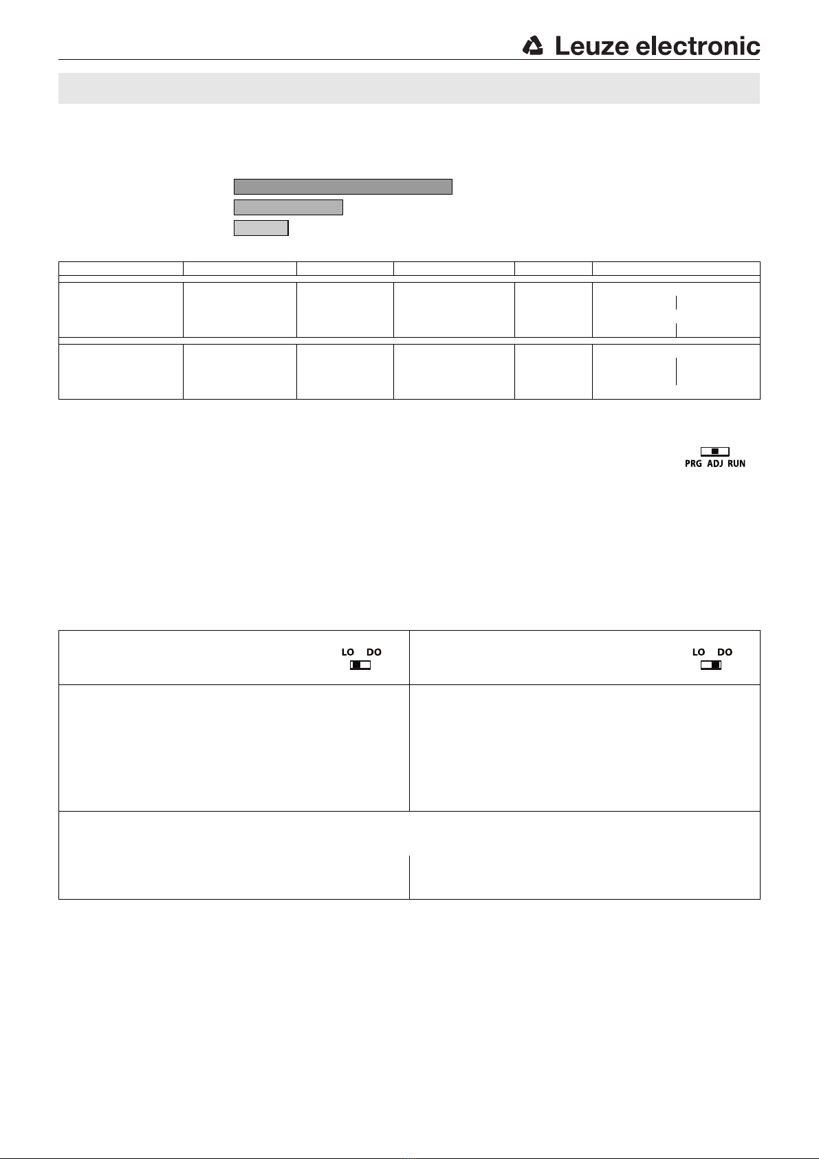
Application Type of object Object size Operating/scanning range Range Configuration
Scanning system
not transparent any long XLR SP-L / Po-2
not transparent medium LR SP-L / Po-1 SP-H / Po-2
transparent large, plane long XLR SP-L / Po-2
medium LR SP-L / Po-1 SP-H / Po-2
Throughbeam system
not transparent rather large long XLR SP-L / Po-2
not transparent small parts medium LR SP-L / Po-1 SP-H / Po-2
transparent any long LR SP-L / Po-1 SP-H / Po-2
short SR SP-H / Po-1
Switching output light switching
Selector switch switching output in position LO,
Setting to maximum range SP-L / Po-2
Switching output dark switching
Selector switch switching output in position DO,
Setting to maximum range SP-L / Po-2
Place object in light beam.
Press button
-
and reduce switching threshold to 000.
The red status LED for the switching output is OFF.
Press button +and keep pressed until the red status LED for the
switching output is ON. Release the button.
Ready - the sensor is now set.
Check cut-in/cut-out point.
Fine adjustment of the switching threshold is possible by briefly pressing
button +or
-
.
Place object in light beam.
Press button
-
and reduce switching threshold to 000.
The red status LED for the switching output is ON.
Press button +and keep pressed until the red status LED for the
switching output is OFF. Release the button.
Ready - the sensor is now set.
Check cut-in/cut-out point.
Fine adjustment of the switching threshold is possible by briefly pressing
button +or
-
.
Remarks:
The sensor is optimally set when the displayed switching threshold is 50 … 100 digits.
If the displayed value is smaller, reduce the range. If the value shown is near to setting limit 999, then set a higher range.
If, at a displayed value of 999, the status LED is not ON, then the range is too
low.
Check the range setting, reduce the object distance.
If, at a displayed value of 999, the status LED is not OFF, then the range is
too low.
Check the range setting, reduce the object distance.
XLR = 4 x SR
LR = 2 x SR
SR
LV462
Table of contents
Other Leuze electronic Amplifier manuals