Leuze electronic GmbH + Co. KG In der Braike 1 D-73277 Owen Tel. +49 (0) 7021 573-0 LV463B - 02
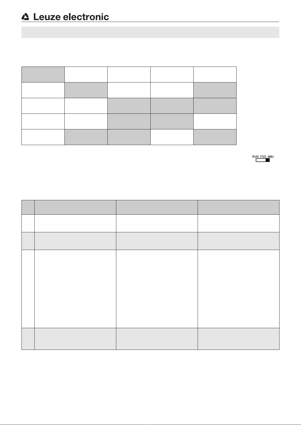
Selecting a subfunction and changing the setting
1.Rock to left or right to select the desired subfunction.
2.Press rocker push button in middle position. The currently set value is displayed statically.
3.Rock to right or left to display the selectable adjustment values - these flash slowly.
4.Accept the new value by pressing the rocker push button in the middle position.
Fast flashing indicates that the new value is accepted.
5.Automatic return to the heading for the subfunction.
6.Press again to statically display the previously selected value.
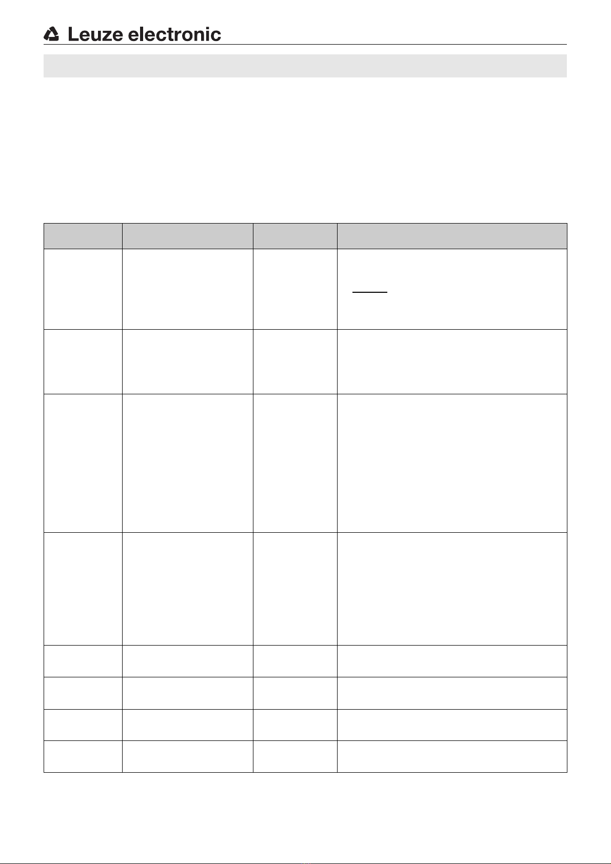
Description of the subfunctions
Subfunction Possible settings /
value range
Factory setting
(default)
Explanation
rESP SPd
Select
response time
trESP = 10 μs(signal range XHS)
15 μs(signal range HS)
50 μs(signal range S)
250 μs(signal range LR)
1000 μs(signal range XLR)
250 μs
The response time is the max. time required by the switching output to
switch to the active state following a signal change at the input.
From this, the switching frequency can be calculated as follows:
Notice: A change to the response time is equivalent to a change to the
signal range.
GAIn SEL
Select
gain
Gain stage
Gn 1 …Gn 8; Auto GAIn
Auto GAIn
The gain stage can be set either by manually presetting a value between
Gn 1 …Gn 8 or automatically by selecting Auto GAIn. The left, red display
shows the current signal value.
The gain stage should be selected so that the signal value is approximately
in the middle of the display area.
If Auto GAIn is selected, the device automatically determines the optimum
gain setting during teaching.
tch SEL
Select teach
mode
Teach modes
1Pttch (static),
2Pttch (static),
dYn tch (dynamic)
1Pttch
Presetting a suitable teach process.
To trigger the teach event, see Teaching operating mode.
1-point teach, static: during teaching, the current signal value is accepted
as the new switching threshold. Actuate the rocker push button to make fine
adjustments to the threshold.
2-point teach, static: the switching threshold is calculated at approxima-
tely midway between two signal values, e.g., teach to two different objects
or teach to the same object at two different distances from the probe. Exa-
mple: signal value 1 = 100digits, signal value 2 = 400digits
Switching threshold = 280digits. Actuate the rocker push button to +or
-
to make fine adjustments to the threshold.
Dynamic teach: suitable for processes that cannot be stopped for teaching.
When the teach event is started, the sensor begins to scan the signal values.
On the left, red display, the signal values are constantly displayed. At the end
of the teach event, the switching threshold is calculated at approximately
midway between the smallest and largest signal value.
Auto thr
Threshold
tracking
Tracking the switching threshold
oFF, On
oFF
The function is only available during dynamic teaching. If the function is
switched on, the switching threshold is automatically and continuously
optimized by the sensor in such a way that maximum functional reliability is
ensured.
This can be used to compensate for, e.g., soiling or process changes.
Warning message:
thr ALrt: The limit of threshold tracking is reached - the sensor conti-
nues to operate. Cleaning and, if necessary, alignment of the
fiber optics recommended.
Error message:
thr Err: The limit of threshold tracking is exceeded - the sensor st-
ops operating. Cleaning and, if necessary, alignment of the
fiber optics urgently necessary.
OFF dLY
Switch-off
delay
0(off), 1…9999 ms (milliseconds) 0
Switch-off delay (OFF Delay):
Individually adjustable from 1 … 9999ms.
Combination options Combining timing functions
OFF ISho
Passing contact
OFF
0(off), 1…9999 ms (milliseconds) 0
Passing contact on fall-back (OFF 1-Shot):
Individually adjustable from 1 … 9999ms.
Combination options Combining timing functions
On dLY
Switch-on
delay
0(off), 1…9999 ms (milliseconds) 0
Switch-on delay (ON Delay):
Individually adjustable from 1 … 9999ms.
Combination options Combining timing functions
On ISho
Passing contact
ON
0(off), 1…9999 ms (milliseconds) 0
Passing contact on actuation (ON 1-Shot):
Individually adjustable from 1 … 9999ms.
Combination options Combining timing functions
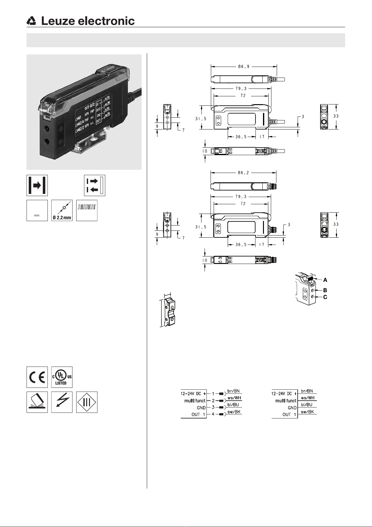
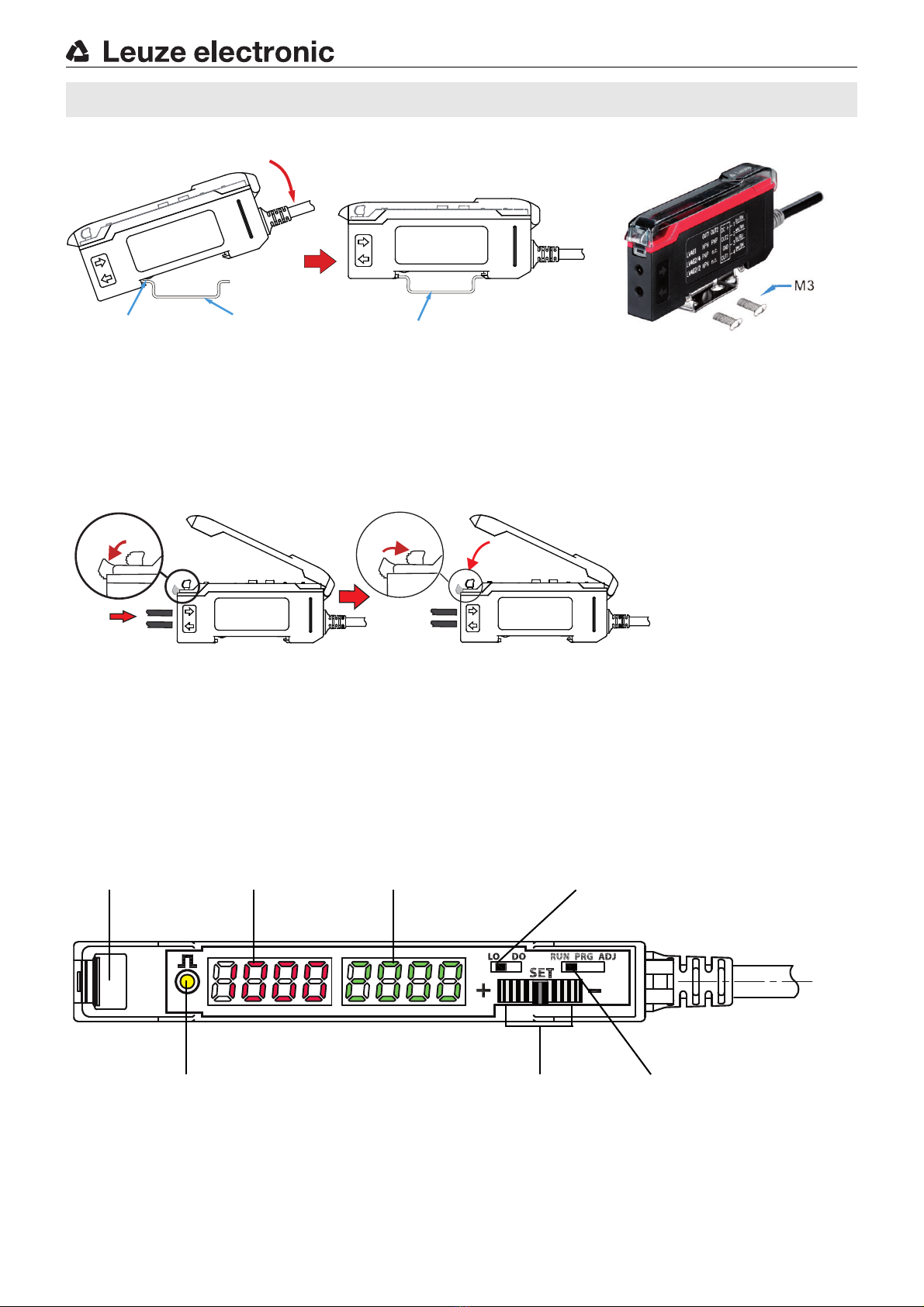
LV463B High-speed amplifier for fiber optics