Leuze electronic MD 748i Quick start guide

MD 748i
MD 248i
PROFINET IO-Link Master
CONNECTING AND OPERATING INSTRUCTIONS
Original Instructions
EN 2016/03 - 50132792
Subject to change without
prior notice

x
Leuze electronic MD 748i / MD 248i 2
© 2016
Leuze electronic GmbH + Co. KG
In der Braike 1
D-73277 Owen / Germany
Trademark Notices
Microsoft and Windows are registered trademarks of Microsoft Corporation.
Other product names mentioned herein may be trademarks and/or registered trademarks of their
respective owners.
First Edition, February 24, 2016
Copyright © 2016. Leuze electronic.
All Rights Reserved.
Leuze electronic makes no representations or warranties with regard to the contents of this document
or to the suitability of the Leuze electronic product for any particular purpose. Specifications subject to
change without notice. Some software or features may not be available at the time of publication. Contact
your reseller for current product information.

x
Leuze electronic MD 748i / MD 248i 3
1Introduction ......................................................................................................... 6
1.1 PRODUCT DESCRIPITON ..................................................................................................... 6
1.2 KEY FEATURES AND BENEFITS.......................................................................................... 6
2Hardware Installation........................................................................................... 8
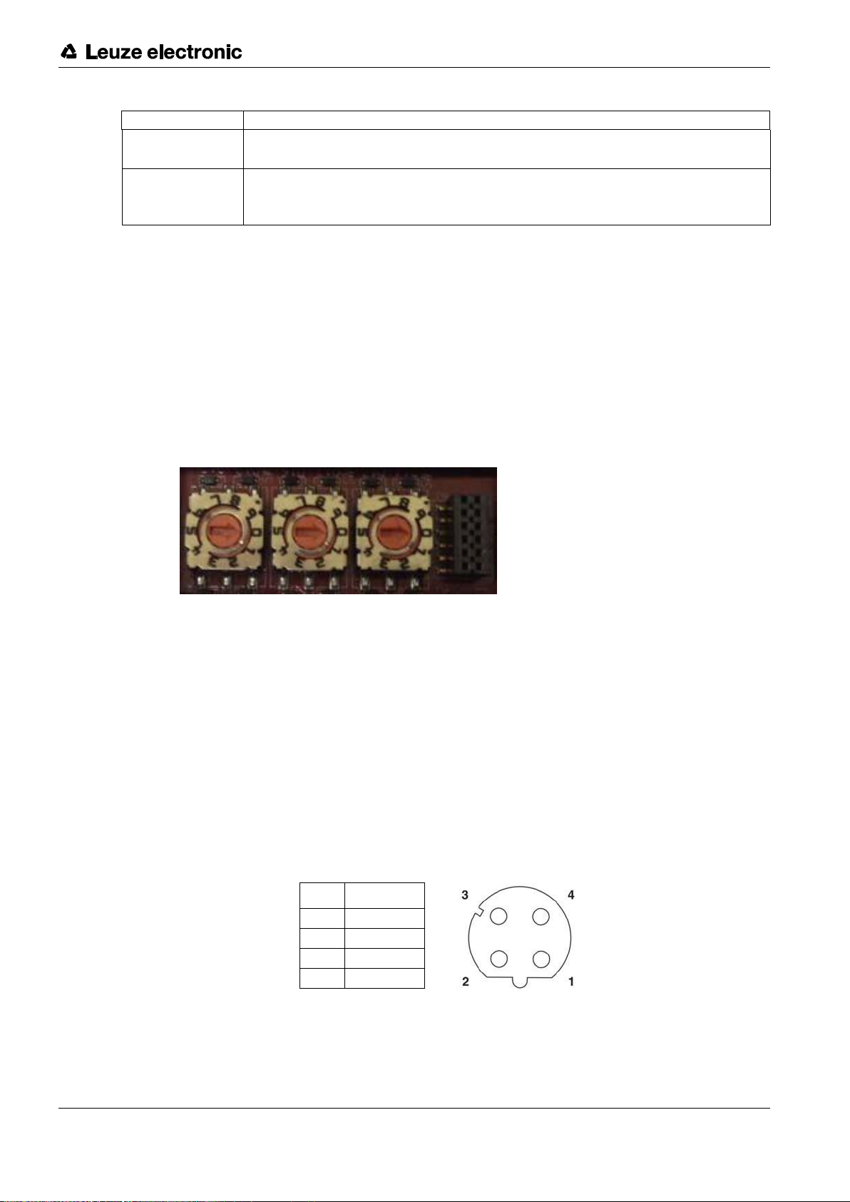
2.1 Setting the Rotary Switch (IP67 Model) ................................................................................... 8
2.1.1 MD 748i-11-42/L5-2222 - Setting the Rotary Switch............................................................ 9
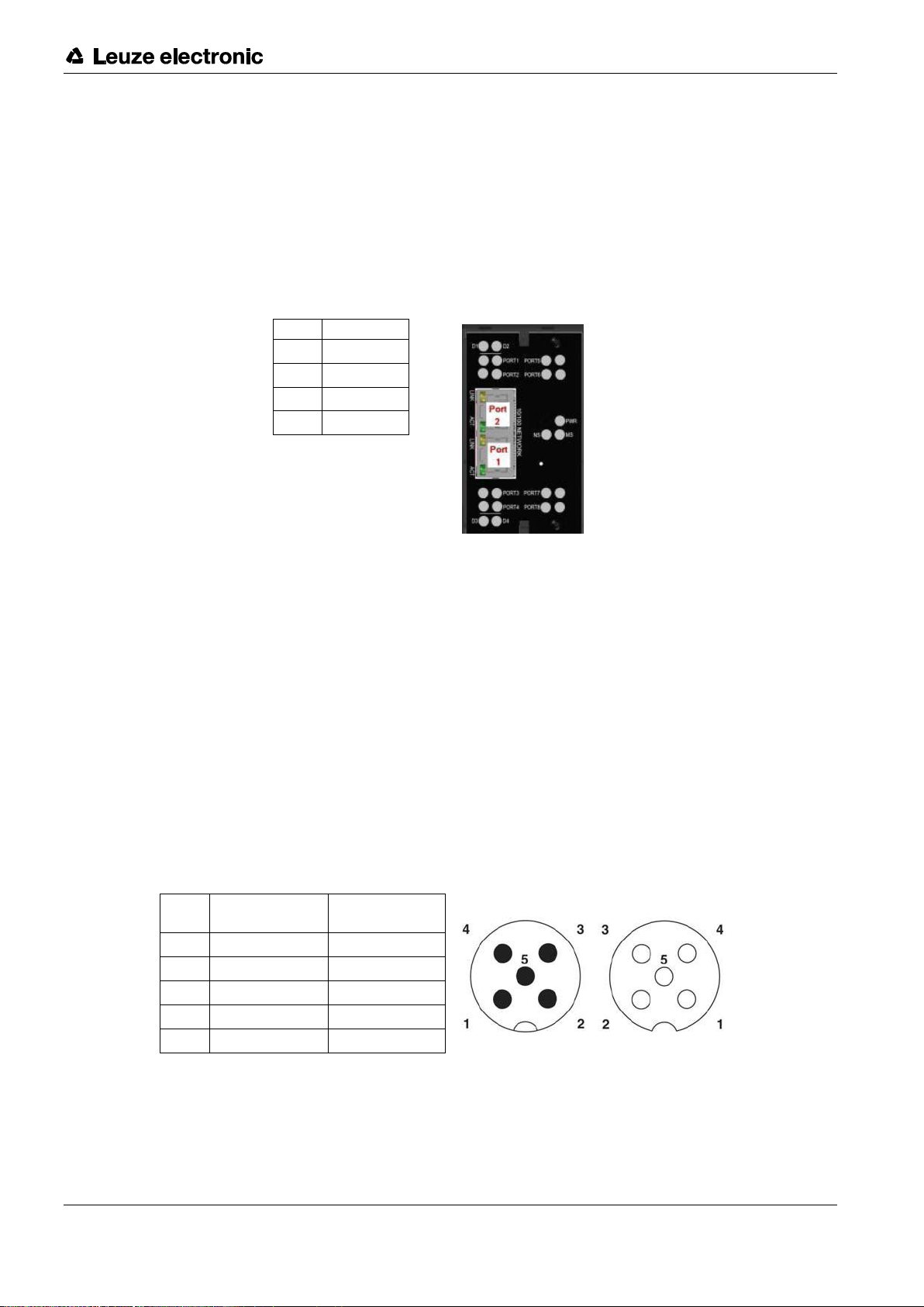
2.2 Connecting to the Network ....................................................................................................... 9
2.2.1 MD 748I-11-42/L5-2222 - Connecting to the Network ......................................................... 9
2.2.2 MD 248i-12-8K/L4-2R2K - Connecting to the Network ...................................................... 10
2.3 Connecting the Power ............................................................................................................ 10
2.3.1 MD 748i-11-42/L5-2222 - Connecting the Power ............................................................... 10
2.3.2 MD 248i-12-8K/L4-2R2K - Connecting the Power.............................................................. 12
2.4 Mounting the IO-Link Master.................................................................................................. 13
2.4.1 MD 748i-11-42/L5-2222 - Mounting.................................................................................... 13
2.4.2 MD 248i-12-8K/L4-2R2K - Mounting .................................................................................. 13
3Configuring the IO-Link Master with STEP 7...................................................... 14
3.1 Overview ................................................................................................................................ 14
3.2 Installing the GSD File (STEP 7 V5.5) ................................................................................... 14
3.3 Configuring the IO-Link Master (STEP 7 V5.5)......................................................................... 14
3.4 IP Address Assignment.......................................................................................................... 15
3.4.1 Assigning an IP Address via IO Controller (DCP) .............................................................. 15
3.4.2 Assigning an IP Address via DHCP.................................................................................... 17
3.4.3 Assigning an IP Address Statically (LOCAL)...................................................................... 18
3.5 Device Name Assignment ...................................................................................................... 22
3.5.1 Assign the Device Name in STEP 7 ................................................................................... 22
3.5.2 Using the Web Interface to Assign the Device Name......................................................... 23
3.6 Setting the IO Device Update Time........................................................................................ 24
3.7 Configuring IO-Link Ports....................................................................................................... 25
3.7.1 IO-Link Port Modules........................................................................................................... 25
3.7.2 Port Status Modules ............................................................................................................ 29
3.7.3 Configuring IO-Link Ports with the Web Interface ............................................................... 31
4IO-Link Master Device Configuration ................................................................. 36
4.1 Setting User Accounts and Passwords .................................................................................. 36
4.2 Configuring Miscellaneous Settings ....................................................................................... 38
5Updating Images and Applications .................................................................... 40
5.1 Images and Application Subassemblies Overview ................................................................ 40
5.1.1 Images................................................................................................................................. 40
5.1.2 Application Subassemblies ................................................................................................. 41
5.2 Using the Web Interface to Update Software........................................................................ 41
5.2.1 Updating Images ................................................................................................................. 41
5.2.2 Updating Application Subassemblies ................................................................................. 42

x
Leuze electronic MD 748i / MD 248i 4
6Connecting Devices .......................................................................................... 44
6.1 Connecting Devices to IO-Link Ports .................................................................................... 44
6.1.1 MD 748i-11-42/L5-2222 IO-Link Ports................................................................................ 44
6.1.2 MD 248i-12-8K/L4-2R2K IO-Link Ports .............................................................................. 45
6.2 Connecting Devices to the Digital IO Ports (MD 248i-12-8K/L4- 2R2K) .............................. 46
6.2.1 Connecting to DI ................................................................................................................. 47
6.2.2 Connecting to DIO............................................................................................................... 47
7Dedicated Digital I/O Port Configuration............................................................. 48
7.1 Digital I/O Settings Page ....................................................................................................... 48
7.2 Editing Digital I/O Settings..................................................................................................... 48
7.3 Digital I/O Setting Parameters............................................................................................... 49
8Loading and Managing IODD Files.................................................................... 52
8.1 IO-Link Device Description Files Page.................................................................................. 52
8.1.1 Preparing IODD Files to Upload ......................................................................................... 52
8.1.2 Uploading IODD Zip Files ................................................................................................... 53
8.1.3 Uploading xml Files or Supporting Files ............................................................................. 55
8.1.4 Viewing and Saving IODD Files.......................................................................................... 56
8.1.5 Deleting IODD Files ............................................................................................................ 57
8.2 IO-Link Device Configuration Summary Page ...................................................................... 58
9Configuring IO-Link Devices .............................................................................. 60
9.1 Port Pages Overview ............................................................................................................. 60
9.2 Editing Parameters - IO-Link Device - Port Table................................................................. 60
9.3 Resetting IO-Link Device Parameters to Factory Defaults ................................................... 62
9.4 Editing Parameters - IO-Link Device ISDU Interface - Port.................................................. 64
10 Utilizing IO-Link Master Features....................................................................... 68
10.1 Data Storage.......................................................................................................................... 68
10.1.1 Uploading Data Storage to the IO-Link Master .................................................................. 68
10.1.2 Downloading Data Storage to the IO-Link Device.............................................................. 69
10.1.3 Automatic Device Configuration ......................................................................................... 69
10.1.4 Automatic Device Configuration Backup ............................................................................ 70
10.2 Device Validation ................................................................................................................... 71
10.3 Data Validation ...................................................................................................................... 73
10.4 Using the Menu Bar Hover Shows Submenu Option............................................................ 74
10.5 IO-Link Test Event Generator ............................................................................................... 75
11 Using the Diagnostics Pages ............................................................................. 77
11.1 IO-Link Port Diagnostics......................................................................................................... 77
11.2 Digital I/O Diagnostics............................................................................................................ 79
11.3 PROFINET IO Diagnostics Page............................................................................................ 80
12 PROFINET IO Reference Information................................................................ 82
12.1 Sample IO-Link Master Gateway Configuration..................................................................... 82

x
Leuze electronic MD 748i / MD 248i 5
12.2 Read PDI Data as Record Data ............................................................................................. 83
12.3 Using the SFB52 RDREC ...................................................................................................... 84
12.4 Read and Write ISDU with the FB IOL_CALL ........................................................................ 85
12.5 Diagnostic Alarm .................................................................................................................... 87
12.5.1 IO-Link Event Mapping Overview ....................................................................................... 87
12.5.2 IO-Link EventCode Mapping............................................................................................... 87
13 Troubleshooting and Technical Support ............................................................. 90
13.1 Troubleshooting ..................................................................................................................... 90
13.2 IO-Link Master LEDs ............................................................................................................. 90
13.2.1 MD 748i-11-42/L5-2222 ...................................................................................................... 90
13.2.2 MD 248i-12-8K/L4-2R2K..................................................................................................... 91
13.3 Contacting Technical Support................................................................................................. 92
13.4 Using Log Files....................................................................................................................... 94
13.4.1 View a Log File.................................................................................................................... 94
13.4.2 Export a Log File ................................................................................................................. 95
13.4.3 Clear a Log File ................................................................................................................... 96
14 TYPE / SPECIFICATION................................................................................... 97
14.1 MD 748i-11-42/L5-2222......................................................................................................... 97
14.2 MD 248i-12-8K/L4-2R2K ....................................................................................................... 98

1Introduction
Leuze electronic MD 748i / MD 248i 6
1 Introduction
1.1 PRODUCT DESCRIPITON
The Leuze electronic IO-Link Master combines the benefits of the IO-Link standard with the popular
industrial PROFINET IO protocol by providing a gateway that is a streamlined bridge between the field
level sensor network and the industrial PROFINET IO backbone, making retrofitting or expansion simple.
The MD 748i IO-Link Master features a rugged IP67 slim-line design incorporating two Fast Ethernet
ports and four IO-Link ports with Class A M12 connectors.
This product is designed for industrial applications with its machine mount design using industrial grade
components.
The MD 248i IO-Link Master easily installs on a standard DIN rail and incorporates two Fast Ethernet
ports, eight IO-Link ports, two DI/DO ports and two DI ports.
This product is designed with industrial grade components and redundant power inputs to make it
exceptionally reliable for critical applications.
The Leuze electronic IO-Link Masters are easily integrated into factory automation networks and are
compatible with both IO-Link and digital IO sensor technologies.
1.2 KEY FEATURES AND BENEFITS
MD 748i
Four channel IO-Link Master to PROFINET IO
Rugged IP67 housing designed for harsh environments, M12 connectors allowing up to four
sensor connections on one master block
Wide operating temperature (0° to +55°C)
MD 248i
Eight port IO-Link Master to PROFINET IO with additional digital inputs on every port allowing
for a possible 10 DI ports with two dedicated DI/DO ports
Screw terminal connectors for IO-Link, Power, and Digital IO
IP20 DIN rail mount enclosure
Wide operating temperature (-40° to +70°C)
Powerful web GUI for configuration and diagnostics, including:
IO-Link device management using the IO-Link device manufacturers IODD file for easy
device configuration
Automatic data storage (upload and download)
Manual data storage (upload and download)
Device validation
Data validation
IO-Link V1.0 and V1.1 compatibility
IO-Link COM1, COM2 and COM3 support (up to 230K baud rate)
PLC access to IO-Link ISDU blocks without complex programming
PROFINET Certification

1Introduction
Leuze electronic MD 748i / MD 248i 7
This document provides installation, configuration and embedded web interface information for the Leuze
electronic Profinet IO-Link Master.
The web interface provides a platform so that you can easily configure, review diagnostic pages, and
access
advanced features, such as the ability to:
Set up user accounts with different user levels and passwords
Load IODD files and configure IO-Link device parameters
Implement manual or automatic data storage (upload or download)
Implement device and/or data validation
The IO-Link Master installation includes the following procedures.
1. Connect the power and Ethernet cable.
2. MD 748I-11-42/L5-2222: If desired, set the rotary switch.
Note: Optionally, you can configure the IP address using the embedded web interface.
3. Configure PROFINET IO.
4. If necessary, upload the latest images for the latest features.
5. Connect the IO-Link and digital I/O devices.
6. Use the web interface to configure the following:
a. If desired, upload the appropriate IODD files for your IO-Link devices for IO-Link device
configuration.
b. Use the Diagnostic pages to monitor or troubleshoot your devices.

2Hardware Installation
Leuze electronic MD 748i / MD 248i 8
2 Hardware Installation
Use the following procedures to install the IO-Link Master hardware:
Setting the Rotary Switch (IP67 Model): see chapter 2.1
Connecting to the Network: see chapter 2.2
Connecting the Power: see chapter 2.3
Mounting the IO-Link Master: see chapter 2.3
Note: The MD 248i-12-8K/L4-2R2K must be installed in a suitable fire, electrical, mechanical enclosure.
2.1 Setting the Rotary Switch (IP67 Model)
You can use the rotary switches under the configuration window on the IO-Link Master to set the lower
3-digits (8 bits) of the static IP address. Optionally, you can leave the rotary switch set to the default and
use the embedded web interface to set the network address.
If the rotary switches are set to a non-default position, the upper 9-digits (24 bits) of the IP address are
then taken from the static network address. The switches only take effect during startup, but the current
position is always shown on Help | SUPPORT page.
Using the rotary switches to set the IP address may be useful in the following situations:
A permanent method to assign IP addresses while setting machines for a special application
where a PC or laptop is not available.
A temporary method to assign IP addresses to several IO-Link Masters so that they do not have
duplicate
addresses to make setting the IP addresses using software easier. After the web
page
to change the IP address, reset the rotary switches back to 000.
An emergency method to return the IO-Link Master back to factory defaults, so that software can
be used to
program the appropriate IP address, and then return the switches back to 000.
Note: If you set the network address using the rotary switches, the rotary switch setting overrides the network
settings in the web interface when the IO-Link Master is initially powered on or after cycling the power.
Switch Setting
Node Address
000
(Default setting)
Use the network configuration stored in the flash. The default network
configuration values are:
•IP address = 192.168.60.101
•Subnet mask = 255.255.255.0
•IP gateway = 0.0.0.0
After completing the hardware installation, see chapter 3 Configuring the IO-Link
Master with STEP 7 to set the network address using the web interface.
001-254
This is the last three digits in the IP address. This uses the first three numbers
from the configured static address, which defaults to 192.168.60.xxx.
Note: If software is used to change the IP address to another range before setting
the rotary switches, the IO-Link Master uses that IP address range. For
example, if the IO-Link Master is set to 10.0.0.250 and the first rotary switch
is set to 2, the IP address would be 10.0.0.200.
255-887
Reserved.
888
Reset to factory defaults. If the IO-Link Master is set to 888 and the IP address
is changed using other methods, the IP address is returned to the default IP
address if the IO-Link Master is rebooted or power cycled.
889-997
Use the network configuration values stored in the flash (reserved).

2Hardware Installation
Leuze electronic MD 748i / MD 248i 9
Switch Setting
Node Address
998
Setting the rotary switches to 998 configures the IO-Link Master to use DHCP
addressing.
999
Use the default IP address. If the IO-Link Master is set to 999 and the IP
address is changed using other methods, the IP address is returned to the
default IP address if the IO-Link Master is rebooted or power cycled.
2.1.1 MD 748i-11-42/L5-2222 - Setting the Rotary Switch
Use the following steps if you want to change the default rotary switch settings.
1. Remove the two Phillips screws securing the switch window.
2. Gently swing open the switch window from the left to the right, allowing it to pivot on the hinge on
the
right side.
3. Turn each dial to the appropriate
position using a small flathead
screwdriver.
Note: If you are using the rotary switch
to assign a temporary IP address,
you may want to leave the
door
open until you use software to set
a permanent IP address. After
doing so, you can close
and seal the window.
The default setting is 000 as shown above.
The arrow points to the switch location. 0 is located at the 3:00
4. Carefully close the window making sure
that it is properly aligned.
5. Reinsert and hand-tighten the two screws making sure that the window is securely sealed.
Note: Failure to reassemble the configuration window properly may compromise IP67 integrity.
2.2 Connecting to the Network
Use the appropriate procedure for your IO-Link Master model.
2.2.1 MD 748I-11-42/L5-2222 - Connecting to the Network
The IO-Link Master provides two Fast Ethernet (10/100BASE-TX), 4-pin female / D-coded
M12 connectors.
Pin
Signal
1
Tx+
2
Rx+
3
Tx-
4
Rx-
You can use this procedure to connect the IO-Link Master to the network.
1. Securely connect one end of a shielded twisted-pair (Cat 5 or higher) M12 Ethernet cable to either
Ethernet port.
2. Connect the other end of the cable to the network.

2Hardware Installation
Leuze electronic MD 748i / MD 248i 10
3. Optionally, use the other Ethernet port to daisy-chain to another Ethernet device.
4. If you did not connect both Ethernet ports, make sure that the unused port is covered with a
connector
cap to keep dust and liquids from getting in the connector.
Note: Ethernet ports must have an approved cable or protective cover attached to the connector to guarantee
IP67 integrity.
2.2.2 MD 248i-12-8K/L4-2R2K - Connecting to the Network
The IO-Link Master provides two Fast Ethernet (10/100BASE-TX) standard RJ45 connectors.
Pin
Signal
1
Tx+
2
Rx+
3
Tx-
4
Rx-
You can use this procedure to connect the IO-Link Master to the network or IO controller.
1. Securely connect one end of the RJ45 Ethernet cable to either Ethernet port.
2. Connect the other end to the network or an IO controller.
3. Optionally, use the other Ethernet port to daisy-chain to another Ethernet device.
Note: If you do not connect the IO-Link Master to an IO controller, an IO controller needs to be connected to the
network
for PROFINET IO configuration.
2.3 Connecting the Power
Use the appropriate information for your IO-Link Master model:
2.3.1 MD 748i-11-42/L5-2222 - Connecting the Power
The MD 748i-11-42/L5-2222 provides dual M12 (A-coded) power
connectors.
Note: Power connectors must have an approved cable or protective
cover attached to the port guarantee to IP67
compliance.
Pin
Input - Male
Output -
Female
1
L+
L+
2
L2+
L2+
3
L-
L-
4
L2-
L2-
5
Not connected
Not connected
The MD 748i-11-42/L5-2222 requires a UL LPS listed power supply with an output rating of 24VDC.

2Hardware Installation
Leuze electronic MD 748i / MD 248i 11
Power Supply
Values
Power Supply In - Maximum (US)
4A
IO-Link Connectors (Ports 1 - 4)
C/Q (Pin 4)
VS (Pins 1 and 3)
200 mA (Maximum)
500 mA (Maximum)
IO-Link Master Power
100mA @ 24VDC (VS)
Power Supply Out (US)
4A * (Maximum)
* US output available is determined by subtracting the following
from
the available input current.
•IO-Link Mode module power
•Actual C/Q current for each IO-Link port
•Actual VS current for each IO-Link port
You can use this procedure to connect the MD 748i-11-42/L5-2222 to a power supply.
Note: Power should be disconnected from the power supply before connecting it to the MD 748i-11-42/L5-
2222.
Otherwise, your screwdriver blade can inadvertently short your power supply terminal
connections to the
grounded enclosure.
1. Securely attach the power cable between the male power connector (PWR In) and the power
supply.
2. Either attach a power cable between the female power connector and another device to which you
want to
provide power or securely attach a connector cap to prevent dust or liquids from getting into
the
connector.
3. Apply the power and verify that the following LEDs are lit indicating that you are ready to attach your
IO-Link or digital I/O devices.
PWR - green lit LED indicates the MD 748i-11-42/L5-2222 is receiving power.
MOD - this LED is not lit, which indicates there are no errors
NET - this LED is off unless a PLC is connected. If a PLC is connected, the LED is lit and green.
LINK should be lit (green) to indicate a valid network connection.
ACT blinks if there is network traffic between the IO-Link Master and the network.
EIP 1/2 should be lit (green) indicating that the link is up if both connectors are connected.
Port LEDs should display in this manner if there is no device attached:
IO-Link port LED should be flashing green indicating that it is
searching for an IO-Link
device.
DI should be off to indicate that there is no device attached to the port.
If the LEDs indicate that you are ready to go to the next installation step:
Program the IP address using the web interface. Refer to chapter 3 for configuring the network
information.
If using the rotary switches to set the IP address, then you are ready to attach devices using
chapter 6.
If the LEDs do not meet the above conditions, you can refer to the IO-Link Master
LEDs
chapter 13,
Troubleshooting and Technical Support.

2Hardware Installation
Leuze electronic MD 748i / MD 248i 12
2.3.2 MD 248i-12-8K/L4-2R2K - Connecting the Power
The MD 248i-12-8K/L4-2R2K provides two redundant power inputs with screw terminals on the top and
bottom of the unit.
Note: Use either power terminal (top or bottom) but DO NOT use both to supply power to the IO-Link Master.
Signal
Description
V-
24VDC Power Supply Return
V-
24VDC Power Supply Return
V+
Primary +24VDC Supply
V+
Secondary +24VDC Supply
Power Supply
Values
Power Supply In
V+
4A (Maximum) *
IO-Link Connectors Ports 1 - 8
C/Q
L+
200 mA (Maximum)
200 mA (Maximum)
Digital IO (D1 and D2 | D3 and D4)
D2, D4
L+
200 mA (Maximum)
200 mA (Maximum)
IO-Link Master Power
100mA @ 24VDC (VS)
Power Supply Out
* The sum of the following must not exceed V+ maximum input current:
•
IO-Link Mode module power
•
Actual C/Q current for each IO-Link port and for D2 and D4 output
•
Actual US current for each IO-Link port
You can use this procedure to connect the IO-Link Master to a power supply.
Note: Power should be disconnected from the power supply before connecting it to the IO-Link Master.
Otherwise, your
screwdriver blade can inadvertently short your terminal connections to the grounded
enclosure.
1. Insert positive and negative wires (12-24AWG) into the V+ and V- contacts.
Note: Use either power terminal (top or bottom) but DO NOT use both to supply power to the IO-Link
Master.
2. Tighten the wire-clamp screws to prevent the wires from coming loose.
3. Apply the power and verify that the following LEDs are lit indicating that you are ready to program
the
IP address and then attach your IO-Link or digital I/O devices.
PWR - green lit LED indicates the MD 248i-12-8K/L4-2R2K is receiving power.
MS, if the LED is off, the IO-Link Master is operating as expected.
NS, if the NS LED is off; that means that there is no PLC connected. If the LED is lit and green,
that
means that a PLC is connected.
LINK should be lit (green) to indicate a valid network connection.
ACT blinks if there is network traffic between the IO-Link Master and the network.
EIP 1/2 should be lit (green) indicating that the link is up if both connectors are connected.
If the LEDs indicate that you are ready to go to the next installation step:

2Hardware Installation
Leuze electronic MD 748i / MD 248i 13
Program the IP address using the web interface. Refer to chapter 3 for configuring the network
information.
If using the rotary switches to set the IP address, then you are ready to attach devices using
chapter 6.
If the LEDs do not meet the above conditions, you can refer to the IO-Link Master
LEDs
in chapter 13,
Troubleshooting and Technical Support.
2.4 Mounting the IO-Link Master
Use the appropriate procedure for your IO-Link Master hardware type.
2.4.1 MD 748i-11-42/L5-2222 - Mounting
Use the following procedure to mount the IO-Link Master. You can mount the IO-Link Master on a mounting
panel or a machine.
1. Verify that the mounting surface is level (flat) to prevent mechanical stress to the IO-Link Master.
2. Attach the IO-Link Master to the surface with two 6mm screws and washers, torque down to 8Nm.
2.4.2 MD 248i-12-8K/L4-2R2K - Mounting
You may want to mount the IO-Link Master after programming the IP address and connecting the IO-Link
and digital
input/output devices.
1. Slide the metal latch down, hook the top of MD 248i-12-8K/L4-2R2K to the DIN rail and release the
latch.
2. Verify that is tightly mounted.
Note: You may want to connect the IO-Link devices before attaching the MD 248i-12-8K/L4-2R2K to the DIN
rail. Use chapter 6 you require IO-Link cabling information.

3Configuring the IO-Link Master with STEP 7
Leuze electronic MD 748i / MD 248i 14
3 Configuring the IO-Link Master with STEP 7
3.1 Overview
PROFINET IO configuration procedures vary between software versions but the following configuration
steps
are required in all cases. Refer to your STEP 7 documentation, if you require step-by-step
procedures.
1. Download, unzip, and upload the GSD file for the IO-Link Master.
2. Insert the IO-Link Master in the PROFINET IO system.
3. Configure the IP address for the IO-Link Master.
4. Assign the PROFINET Device Name.
5. Set the IO Device Update Time.
6. Configure the IO-Link ports.
a. Configure IO-Link port modules.
b. Configure port status modules.
c. If desired, configure data storage, automatic or manual - upload or download.
d. If desired, configure device validation and data validation.
7. Use chapter 12 PROFINET IO Reference Information to complete configuration after
attaching the
IO-Link devices.
The following subsections provides PROFINET IO configuration procedures using
STEP 7 V5.5
:
Installing the GSD File (STEP 7 V5.5): see chapter 3.1
Configuring the IO-Link Master (STEP 7 V5.5): see chapter 3.2
Assign IP Address: see chapter 3.3
IP Address Assignment: see chapter 3.4
Device Name Assignment: see chapter 3.5
Setting the IO Device Update Time: see chapter 3.6
3.2 Installing the GSD File (STEP 7 V5.5)
Use the following procedure to install the GSD file for PROFINET IO using STEP 7 V5.5.
1. Unzip GSDML-V2.31-Leuze electronic-IOLink-yyyymmdd.zip to a working directory.
2. Open SIMATIC STEP 7 | HW Config.
3. Use Menu Options | Install GSD Files to install the GSD file.
4. If an older version of the GSD file was installed before, you may need to remove the IO-Link
Master object from an existing project, and reinsert it after the new GSDML file is installed.
3.3 Configuring the IO-Link Master (STEP 7 V5.5)
Select the IO-Link Master from the Hardware Catalog window and insert it into a PROFINET-IO- System
in the HW Config (PROFINET IO -> Additional Field Device -> Gateway -> Leuze electronic IO-Link
Master ->MD 248i-12-8K/L4-2R2K) as shown in Figure 1.

3Configuring the IO-Link Master with STEP 7
Leuze electronic MD 748i / MD 248i 15
Figure 1: Inserting an MD 248i-12-8K/L4-2R2K into a PROFINET IO System
3.4 IP Address Assignment
Leuze electronic IO-Link Master gateways support three methods for IP address assignment according to
GSDHML Specification
V2.31
.
DCP - The DAP supports IP address assignment via Discovery and basic Configuration Protocol
(DCP).
See 3.4.1 Assigning an IP Address via IO Controller (DCP) for procedures.
DHCP - The DAP supports the Dynamic Host Configuration Protocol for IP address assignment.
See 3.4.2 Assigning an IP Address via DHCP for procedures.
LOCAL - The DAP supports a device specific method for IP address assignment. See 3.4.3
Assigning an IP Address Statically (LOCAL) for procedures.
3.4.1 Assigning an IP Address via IO Controller (DCP)
An IO controller can assign an IP address to the Leuze electronic IO-Link Master gateway via DCP. The IO
controller and the
Leuze electronic IO-Link Master gateway have to be on the same subnet. The IO-Link
Master default IP address is: 192.168.60.101 and the
subnet mask is 255.255.255.0.
1. Double-click the X1 PNIO-IO interface of the
IO control to open the
Properties
window.
2. On the General tab, click the Properties button,
which opens the
Ethernet interface Properties
window.

3Configuring the IO-Link Master with STEP 7
Leuze electronic MD 748i / MD 248i 16
Figure 2: IO Controller Ethernet Interface Properties
3. Uncheck the Use different method to obtain IP address option.
4. Manually enter the IP address and subnet
mask for the IO controller.
In this example the IO controller was assigned
an IP address of 10.0.0.31 and a subnet mask
of
255.0.0.0.
5. Double-click the IO-Link Master; check Assign IP address via IO controller as shown in Figure 3.
Figure 3: IO-Link Master Properties
6. On the General tab, click the Ethernet button,
which opens the
Ethernet interface properties
window, where you can specify what IP
address the IO controller should assign to the
IO-Link
Master.

3Configuring the IO-Link Master with STEP 7
Leuze electronic MD 748i / MD 248i 17
Steps 2 through 4 are necessary in STEP 7 V5.5 so
that both the IO controller and the IO-Link Master are
on the same subnet. Otherwise, the Assign IP address via IO controller function may not work correctly.
In this example, IP address 10.0.0.100 is assigned to the IO-Link Master via the IO controller.
3.4.2 Assigning an IP Address via DHCP
The Leuze electronic IO-Link Master gateway supports DHCP for IP address assignment. DHCP is
disabled by default.
Use the following steps to enable DHCP.
Note: The IO-Link Master default IP address is: 192.168.60.101 and the subnet mask is 255.255.255.0. You
may need to
change your laptop or PC IP address range to access the IO-Link Master web interface.
1. Open a web browser and enter the IO-Link Master IP address.
2. Click Configuration | Network.
3. Click EDIT button.
Figure 4: Web Network Configuration Page

3Configuring the IO-Link Master with STEP 7
Leuze electronic MD 748i / MD 248i 18
4. Change IP Type from static to dhcp.
Figure 5: Web Network Configuration Page: DHCP setting
5. Click the SAVE button.
Once DHCP is enabled, the IO-Link Master attempts to obtain an IP address from a DHCP server. If a new
IP address
is assigned by a DHCP server, then the IO-Link Master switches to the new IP address
immediately. This may interfere
with communications between the device and the IO controller.
The Obtain IP address from a DHCP server option in the
Edit Ethernet Node
window in STEP 7 (Figure
7: Configure IP Address and Device Name) is not supported. DHCP can only be enabled or
disabled via the web interface.
Note: An IO controller can overwrite DHCP IP assignment by assigning IP address via DCP.
The next configuration step is to assign the device name, see 3.5 Device Name Assignment.
3.4.3 Assigning an IP Address Statically (LOCAL)
IP addresses can also be assigned statically using one of the following methods:
The LOCAL method as defined in the GSDML Specification
Embedded web interface
3.4.3.1 Assign IP Address Statically Using STEP 7
Use the following procedure if you want to use the LOCAL method using STEP 7.
1. In the STEP 7
HW Config
window, double-click the IO-Link Master object to open up the
Properties
window.

3Configuring the IO-Link Master with STEP 7
Leuze electronic MD 748i / MD 248i 19
Figure 6: IO-Link Master properties
2. Uncheck the Assign IP address via IO controller option and click OK.
The IO controller will not attempt to assign IP address to the IO-Link Master. You must assign a
static IP address to the IO-Link Master manually.
3. Select the IO-Link Master in HW Config, open the Edit Ethernet Node window (Figure 7:
Configure IP Address and Device Name) by using menu PLC | Ethernet | Edit Ethernet Node
option.
4. Once opened, click the Browse button, which opens the
Browse Network
window.
The IO-Link Master should be displayed as an Leuze electronic IO-Link Master with a default IP
address of 192.168.60.101.
5. Select the IO-Link Master and click the OK button to return to the
Edit Ethernet Node
window.
6. Enter the desired IP configurations.
In Figure 7: Configure IP Address and Device Name the IO-Link Master was configured to use a
static IP address 10.0.0.100, subnet mask 255.0.0.0 and no router.
7. Click the Assign IP Configuration button, the IP configuration is assigned to the IO-Link Master.

3Configuring the IO-Link Master with STEP 7
Leuze electronic MD 748i / MD 248i 20
Figure 7: Configure IP Address and Device Name
The next configuration step is to assign the device name, see 3.5 Device Name Assignment.
3.4.3.2 Assign IP Address Statically Using the Web Page
You can use the following procedure to configure a static IP address. The IO-Link Master web interface
switches to the
new IP address immediately.
Note: The IO-Link Master default IP address is: 192.168.60.101 and the subnet mask is 255.255.255.0. You
may need to
change your laptop or PC IP address range to access the IO-Link Master web.
1. Open a web browser and enter the IO-Link Master IP address.
2. Click Configuration | Network.
This manual suits for next models
1
Table of contents
Other Leuze electronic Recording Equipment manuals