Leuze electronic S300 User manual

S300
Safety Switches
SAFE IMPLEMENTATION AND OPERATION
Original operating instructions
EN 2011/09 - 607280
We reserve the right to
make technical changes

© 2011
Leuze electronic GmbH + Co. KG
In der Braike 1
D-73277 Owen - Teck / Germany
Phone: +49 7021 573-0
Fax: +49 7021 573-199
http://www.leuze.com
info@leuze.de

Leuze electronic S300 3
TNT 35/7-24V
1 About this document............................................................................................ 5
1.1 Other applicable documents ................................................................................................5
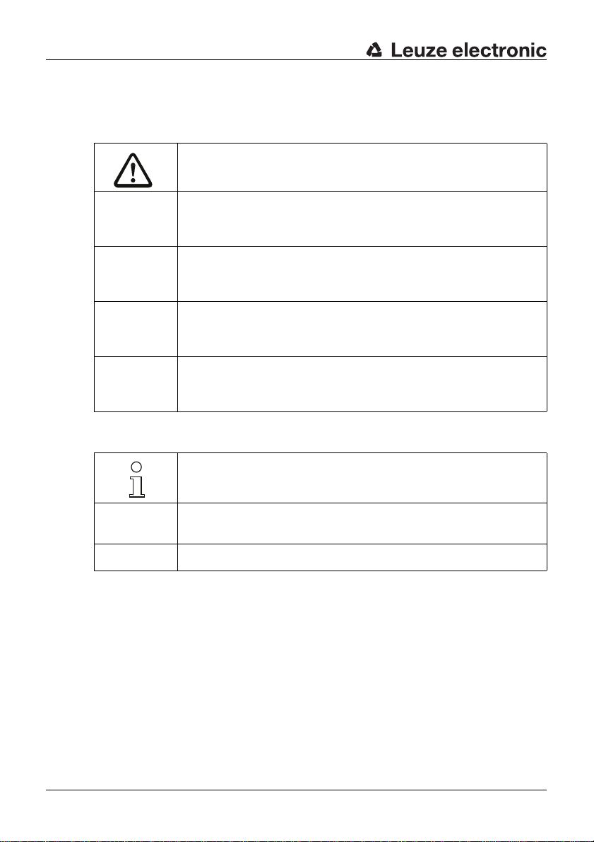
1.2 Used symbols and signal words ..........................................................................................6
2 Safety................................................................................................................... 7
2.1 Approved purpose and foreseeable improper operation......................................................8
2.1.1 Proper use.....................................................................................................................................8
2.1.2 Foreseeable misuse ....................................................................................................................10
2.2 Competent personnel.........................................................................................................10
2.3 Responsibility for safety.....................................................................................................10
2.4 Exemption of liability ..........................................................................................................11
3 Device description ............................................................................................. 12
4 Functions ........................................................................................................... 17
5 Applications ....................................................................................................... 18
6 Mounting............................................................................................................ 19
6.1 Adjusting the switching and approach direction.................................................................19
6.2 Mounting the Safety Position Switch..................................................................................22
7 Electrical connection.......................................................................................... 26
7.1 Connecting the contact block.............................................................................................26
7.2 Contact block characteristics .............................................................................................27
8 Setting the device into service........................................................................... 29
9 Testing............................................................................................................... 30
9.1 To be performed prior to the initial start-up by competent personnel.................................30
9.2 To be performed periodically by competent personnel......................................................30
9.3 To be performed daily by the operating personnel ............................................................31
10 Cleaning............................................................................................................. 32
11 Disposing........................................................................................................... 33
12 Service and support........................................................................................... 34
13 Accessories ....................................................................................................... 35
13.1 Accessory dimensional drawings.......................................................................................36
14 Technical data ................................................................................................... 37

About this document
Leuze electronic S300 5
TNT 35/7-24V
1 About this document
1.1 Other applicable documents
The information on the S300 Safety Position Switchis divided into two documents.
Document "S300 Application information" contains only the most important safety
notices.
ªFor the safe implementation, testing and operation, download document S300
Safe implementation and operation from http://www.leuze.com/s300/ or
request it from service.schuetzen@leuze.de or tel. +49 8141 5350-111.
Table 1.1: Documents on the S300 Safety Position Switch
Purpose and target group Title Source
Detailed information for all
users S300 Safe implementation
and operation (this docu-
ment)
On the Internet, download
from: http://www.leuze.com/
s300/
Basic information for techni-
cians and operating company S300 Application information Print document part
no. 607238 included in the
delivery contents of the
product

About this document
6 S300 Leuze electronic
1.2 Used symbols and signal words
Table 1.2: Warning symbols and signal words
Table 1.3: Other symbols
Symbol for dangers
NOTICE Signal word for property damage
Indicates dangers that may result in property damage if the measures for
danger avoidance are not followed.
CAUTION Signal word for minor injury
Indicates dangers that may result in minor injury if the measures for dan-
ger avoidance are not followed.
WARNING Signal word for severe injury
Indicates dangers that may result in severe or fatal injury if the measures
for danger avoidance are not followed.
DANGER Signal word for life-threatening danger
Indicates dangers that will result in severe or fatal injury if the measures
for danger avoidance are not followed.
Symbol for tips
Text passages with this symbol provide you with further information.
ªSymbols for action steps
Text passages with this symbol instruct you to perform actions.
xxx Placeholder in the product description for all variants

Safety
Leuze electronic S300 7
TNT 35/7-24V
2 Safety
Before using the Safety Position Switch, a risk evaluation must be performed
according to valid standards (e.g. EN ISO 12100-1, EN ISO 13849-1,
EN ISO 14121). For mounting, operating and testing, document S300 Safe imple-
mentation and operation, application information as well as all applicable national
and international standards, regulations, rules and directives must be observed.
Observe and print out relevant and supplied documents and distribute to the
affected personnel.
The following standards apply for the risk evaluation at the protective device prior
to using the Safety Position Switch:
• EN ISO 14121, Safety of machinery, risk evaluation
• EN ISO 12100-1, Safety of machinery
• EN ISO 13849-1, Safety-related parts of control systems
The realizable category of integration in control circuits acc. to EN ISO 13849-1 is
dependent on the used contact block, wiring and mechanical conditions.
In particular, the following national and international legal regulations apply for the
start-up, technical inspections and work with Safety Position Switch:
• Machinery directive 2006/42/EC
• Low voltage directive 2006/95/EC
• Use of work equipment directive 89/655 EEC
• Safety regulations
• Accident-prevention regulations and safety rules
• Ordinance on Industrial Safety and Health and Labor Protection Act
• Device Safety Act
For safety-related information you may also contact the local authorities (e.g.,
industrial inspectorate, employer's liability insurance association, labor inspec-
torate, labor protection and health authority).

Safety
8 S300 Leuze electronic
2.1 Approved purpose and foreseeable improper operation
2.1.1 Proper use
• The Safety Switch must only be used after it has been selected in accor-
dance with the respectively applicable instructions and relevant standards,
rules and regulations regarding labor protection and safety at work, and
after it has been installed on the machine, connected, commissioned, and
checked by a competent person.
• When selecting the Safety Switch it must be ensured that its safety-related
capability meets or exceeds the required performance level PLrascertained
in the risk assessment.
• It must be in perfect condition and inspected regularly.
• The switching process must only be triggered by an actuator approved for
this Safety Switch as well as a steering device in accordance with the speci-
fications. Both must be connected to the fixed actuator holder or moveable
guard in a permanent and tamperproof manner.
S300 Safety Switches must be connected in such a way that a dangerous state
can only be activated while the protective device is closed and so that the
dangerous state stops upon opening of the protective device. It must not be used
if the point of operation can be accessed during the lag time before the dangerous
state has ended.
Connection conditions:
• the dangerous state can only be activated while the protective device is
closed
• opening the protective device while the machine is running triggers a stop
command and ends the dangerous state
WARNING
A running machine can cause severe injuries!
ªMake certain that, during all conversions, maintenance work and inspections,
the system is securely shut down and protected against being restarted
again.

Safety
Leuze electronic S300 9
TNT 35/7-24V
Furthermore, the S300 Safety Position Switch must not be used under the
following conditions:
• the actuation surface (e.g. of the machine or sliding gate) for the actuator is
not form-fitting with positive actuation
• rapidly changing ambient temperature (leads to condensation)
• in the event of strong physical shocks
• in explosive or easily flammable atmospheres
• the mounting locations are not sufficiently stable
• the safety of multiple persons is dependent on the function of this Safety
Switch (e.g. nuclear power plants, trains, aircraft, motor vehicles, incinera-
tors, medical devices)
Handling the Safety Position Switch:
ªObserve the permissible environmental conditions for storage and operation
(see chapter 14).
ªImmediately replace damaged Safety Position Switch according to these
instructions.
ªUse cable gland, insulation materials and connecting wires of the appropriate
protection rating.
ªProtect the Safety Position Switch from penetrating foreign bodies (e.g. shav-
ings, sand and blasting agent).
ªBefore performing painting work, cover theactuation head, actuator and name
plate.
ªImmediately clean any contamination from the Safety Position Switch that
impacts function according to these instructions.
ªMake no structural changes to the Safety Position Switch and/or actuator.
ªThe switching direction may only be changed following an adequate risk eval-
uation and according to the dangerous direction of movement.
ªThe Safety Switch must be exchanged after a maximum of 20 years.
For machines with longer slowdowns, a Safety Locking Device must be used.

Safety
10 S300 Leuze electronic
2.1.2 Foreseeable misuse
Any use other than that defined under the "approved purpose" or which goes
beyond that use of the Safety Switch is considered improper use!
E.g. - using without non-detachably mounted actuator or start-up device
• looping into the safety circuit parts that are not relevant to safety
• using the switch as a limit stop
2.2 Competent personnel
Prerequisites for competent personnel:
• suitable technical training
• knows the rules and regulations for labor protection, safety at work and
safety technology and can assess the safety of the machine
• knows the instructions for the Safety Position Switch and the machine
• was instructed by the responsible individuals on the mounting and operation
of the machine and of the Safety Position Switch
2.3 Responsibility for safety
Manufacturer and operating company must ensure that the machine and imple-
mented Safety Position Switch function properly and that all affected persons are
adequately informed and trained.
The type and content of all imparted information must not lead to unsafe actions
by users.
The manufacturer of the machine is responsible for:
• safe machine construction
• safe implementation of the Safety Position Switch
• imparting all relevant information to the operating company
• adhering to all regulations and directives for the safe starting-up of the
machine
The operating company is responsible for:
• instructing the operating personnel
• maintaining the safe operation of the machine
• adhering to all regulations and directives for labor protection and safety at
work
• regular testing by competent personnel

Safety
Leuze electronic S300 11
TNT 35/7-24V
2.4 Exemption of liability
Leuze electronic GmbH + Co. KG is not liable in the following cases:
• Safety Position Switch is not used as intended
• safety notices are not adhered to
• mounting and electrical connection are not properly performed
• reasonably foreseeable misuse is not taken into account

Device description
12 S300 Leuze electronic
3 Device description
The Safety Position Switch of the S300 series is an electro-mechanical switching
device in a housing made of metal or self-extinguishing,highly viscous plastic; the
device satisfies protection rating IP 67.
Models with different actuators, contact sets and connection options are available.
The 300 series can therefore cover a variety of mechanical and electrical applica-
tions.
1 Actuator head
2 Actuator
3 Housing cover
4 Name plate (connection data, production code and year of manufacture)
1
2
3
4
1
2
3
4

Device description
Leuze electronic S300 13
TNT 35/7-24V
Table 3.1: S300 Safety Position Switch
Figure 3.1: Dimensions of S300-M0C3-M20-15 and S300-M13C3-M20-15 in
mm
Article Part No. Description
S300-M0C3-M20-15 63000300 1NC + 1NO, metal design roller plunger, 3 cable
entries
S300-M13C3-M20-15 63000301 2NC + 1NO, metal design roller plunger, 3 cable
entries
S300-M0C3-M20-31 63000302 1NC + 1NO, metal design roller lever, 3 cable entries
S300-M13C3-M20-31 63000303 2NC + 1NO, metal design roller lever, 3 cable entries
S300-M13C3-M20-CB 63000304 2NC + 1NO, metal design, short actuator holder,
3 cable entries
S300-M13C3-M20-SB 63000305 2NC + 1NO, metal design, long actuator holder,
3 cable entries
S300-P13C1-M20-CB 63000306 2NC + 1NO, plastic design, short actuator holder,
1 cable entry
S300-P13C1-M12-CB 63000307 2NC + 1NO, plastic design, short actuator holder,
1 cable entry / M12 plug
S300-P13C1-M20-SB 63000308 2NC + 1NO, plastic design, long actuator holder,
1 cable entry
S300-P13C1-M12-SB 63000309 2NC + 1NO, plastic design, long actuator holder,
1 cable entry / M12 plug
56
57
18
33
14.5
6
14.5
40
4
13
50
107
5.2x6.2

Device description
14 S300 Leuze electronic
Figure 3.2: Dimensions of S300-M0C3-M20-31 and S300-M13C3-M20-31 in
mm
Figure 3.3: Dimensions of S300-M13C3-M20-CB in mm
Figure 3.4: Dimensions of S300-M13C3-M20-SB in mm
56
57
18
33
14.5
6
40
31
7
20
36
55
62
22
119
5.2x6.2
56
57
18
33
14.5
6
40
31
22
M 5
3028
5.2x6.2
56
57
18
33
14.5
6
40
M 5
31
41
22
28
5.2x6.2

Device description
Leuze electronic S300 15
TNT 35/7-24V
Figure 3.5: Dimensions of S300-P13C1-M20-CB and S300-P13C1-M12-CB
in mm
Figure 3.6: Dimensions of S300-P13C1-M20-SB and S300-P13C1-M12-SB
in mm
Figure 3.7: Dimensions of S300-P13C1-M12-xxx in mm (M12 plug dimensions)
The actuator head can be turned in 90° increments and set to 4 approach direc-
tions. The roller lever can be mounted with a 180° rotation and can be positioned
in 10° increments.
5.3x7.3
40 30
39
30
60
5.3
16
6
28
M 5
31.5
31
22
5.3x7.3
40 30
39
30
60
5.3
16
6
28
M 5
42.5
31
22
15
M12x1 23
13.3

Device description
16 S300 Leuze electronic
Figure 3.8: Adjustment options
10°

Functions
Leuze electronic S300 17
TNT 35/7-24V
4 Functions
The Safety Position Switch signals to the safety switching device whether the
protective device is closed. Depending on actuator and set actuation directions,
the Safety Position Switch can also signal alternating directions of danger situa-
tions. Release of the actuator closes the safety contacts; pressure on the actuator
forces opening of the safety contacts upon opening of the protective device (e.g.
a sliding gate). As a result, the machine can only be switched on if the protective
device is closed.

Applications
18 S300 Leuze electronic
5 Applications
The Safety Position Switch is suitable for e.g. the following protective devices:
• turning or sliding protective hoods and protective flaps
• laterally moveable protective gratings or sliding gates
• machine-actuated supplementary cut-off (e.g. in combination with other
Safety Switches)

Mounting
Leuze electronic S300 19
TNT 35/7-24V
6 Mounting
6.1 Adjusting the switching and approach direction
ªLoosen the 4 screws on the actuator head.
ªLift the actuator head.
WARNING
Severe accidents may result if the Safety Position Switch is not mounted
properly!
The protective function of the Safety Position Switch is only ensured if appropri-
ately and professionally mounted for the respective, intended area of applica-
tion.
ªMounting may only be performed by competent personnel.
ªObserve standards, regulations and these instructions.
ªObserve mounting conditions exactly.
ªUse separate mechanical limit stop (see figure 6.3).
ªSet the distances to the actuator and its angles so that it is impossible to cir-
cumvent or encompass the protective device.
ªProtect the housing from materials penetrating the enclosure (environmental
conditions (see chapter 14)).
ªTest to ensure proper function.

Mounting
20 S300 Leuze electronic
ªIf necessary, set the internal plunger to the correct switching direction in 90°
increments (relative to the NC contacts).
WARNING
Severe accidents may result if the switching function is not set properly!
ªSet the switching direction so that the NC contacts open upon opening of the
protective device.
Table of contents
Other Leuze electronic Switch manuals

Leuze electronic
Leuze electronic CSL710-T05-1280.A-M12 User manual

Leuze electronic
Leuze electronic S400 User manual

Leuze electronic
Leuze electronic S20 Series User manual

Leuze electronic
Leuze electronic S20 Series User manual

Leuze electronic
Leuze electronic S200 User manual

Leuze electronic
Leuze electronic ESB200 Series User manual
Popular Switch manuals by other brands

Wisenet
Wisenet SWT-G0803MG Series quick start guide

Dell
Dell PowerConnect 7048 Getting started guide

Versitron
Versitron S72450 installation guide

Brocade Communications Systems
Brocade Communications Systems FastIron FGS624P Hardware installation guide

Sonoff
Sonoff DIY POWR3 user manual

Kraus
Kraus KWDB-10 installation guide