Leuze electronic BPS 34 3
Leuze electronic Figures and tables
Figure 2.1: Example for the attachment of the sticky label with warning notices ........................... 7
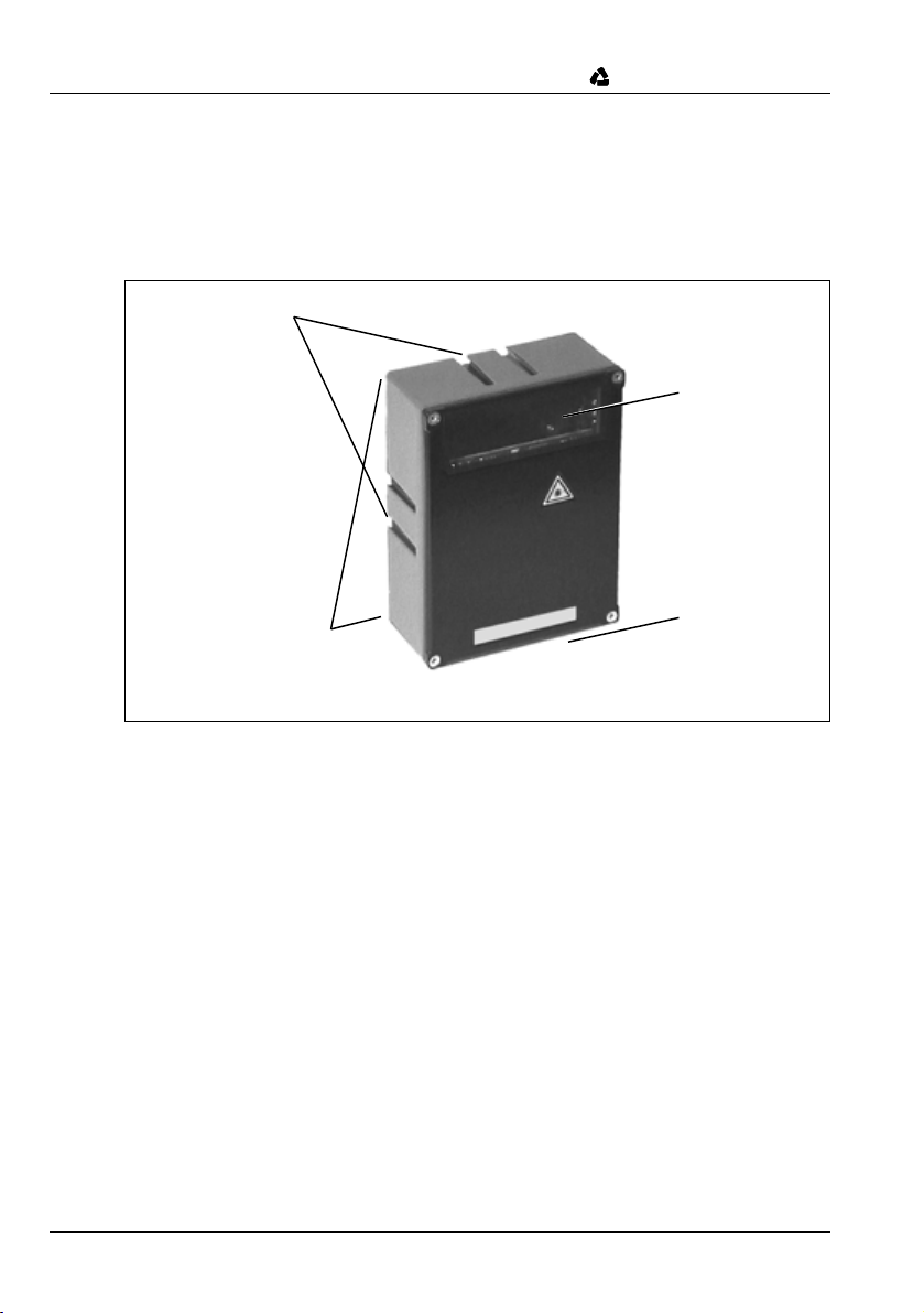
Figure 3.1: BPS 34 device construction ......................................................................................... 8
Table 4.1: General Specifications ............................................................................................... 11
Table 4.2: LED states MS 34 103 / MS 34 105 ........................................................................... 12
Figure 4.1: BPS 34 with MS 34 105 ............................................................................................. 12
Figure 4.2: Dimensioned drawing BPS 34.................................................................................... 13
Figure 4.3: Dimensioned drawing MS 34 103 / MS 34 105 ..........................................................13
Figure 4.4: Scanning curve BPS 34 ............................................................................................. 14
Table 5.1: Accessories / Order Designation................................................................................ 15
Figure 5.1: Modular Service Display MSD 1 101.......................................................................... 16
Figure 5.2: Mounting device BT 56............................................................................................... 17
Figure 6.1: Mounting example BPS 34......................................................................................... 19
Figure 6.2: Beam outlet on the BPS 34 ........................................................................................21
Figure 6.3: Application example ................................................................................................... 22
Figure 6.4: View of the inside of the MS 34.................................................................................. 23
Figure 6.5: Connection assignment of the BPS 34 with MS 34 103 / MS 34 105 ........................24
Figure 6.6: Connection diagram switching inputs and outputs BPS 34........................................ 26
Table 7.1: Overview of the project modules ................................................................................ 28
Table 7.2: Parameters for Module 1............................................................................................29
Table 7.3: Input data for Module 1 .............................................................................................. 29
Table 7.4: Parameters for Module 2............................................................................................30
Table 7.5: Parameters for Module 3............................................................................................30
Table 7.6: Output data for Module 4............................................................................................ 31
Table 7.7: Output data for Module 4............................................................................................ 31
Table 7.8: Parameters for Module 5............................................................................................32
Table 7.9: Parameters for Module 6............................................................................................32
Table 7.10: Parameters for Module 7............................................................................................33
Table 7.11: Input data for Module 7 ..............................................................................................34
Table 7.12: Parameters for Module 8............................................................................................35
Table 7.13: Output data for Module 8............................................................................................ 36
Table 7.14: Parameters for Module 9............................................................................................37
Table 7.15: Input data for Module 9 ..............................................................................................38
Table 7.16: Output data for Module 9............................................................................................ 38
Table 7.17: Parameters for Module 10..........................................................................................39
Table 7.18: Parameters for Module 11..........................................................................................40
Table 7.19: Output data for Module 11.......................................................................................... 40
Table 7.20: Input data for Module 12 ............................................................................................ 41
Table 7.21: Parameters for Module 13..........................................................................................42
Table 7.22: Input data for Module 13 ............................................................................................ 42
Table 7.23: Output data for Module 13.......................................................................................... 42
Table 7.24: Parameters for Module 14..........................................................................................43
Table 7.25: Parameters for Module 15..........................................................................................44
Table 7.26: Parameters for Module 16..........................................................................................45
Table 7.27: Output data for Module 16.......................................................................................... 45
Table 7.28: Parameters for Module 17..........................................................................................46
Table 7.29: Output data for Module 17.......................................................................................... 46