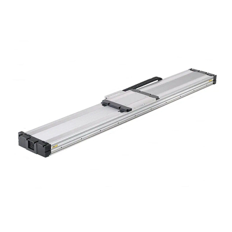
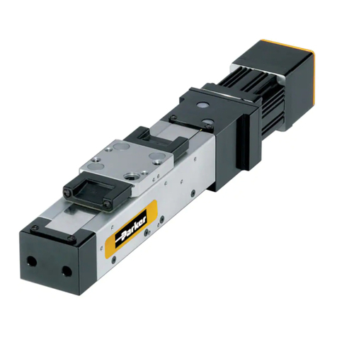
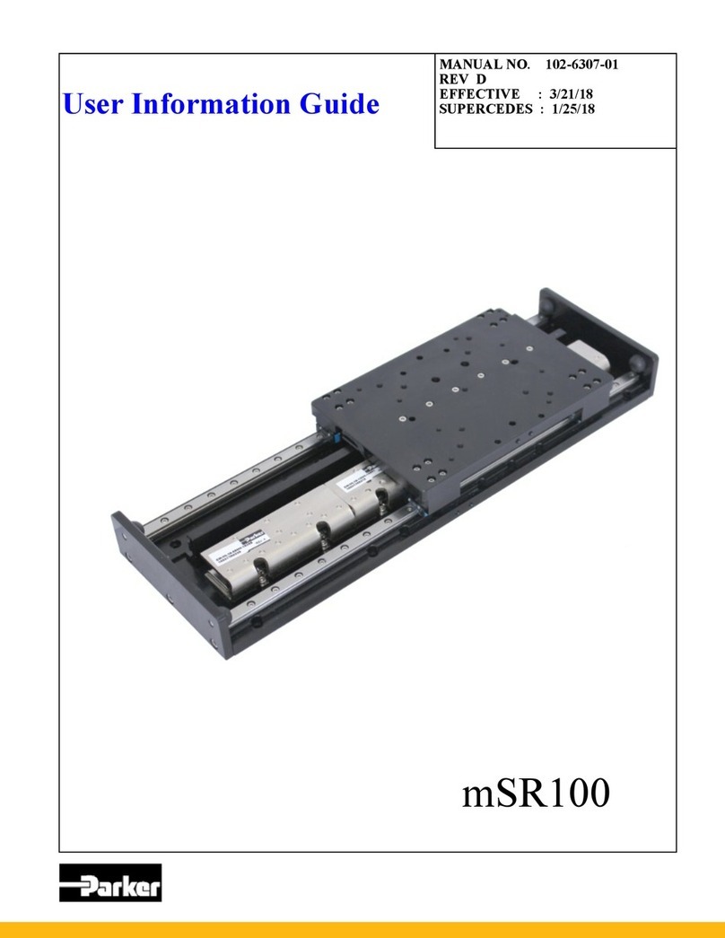
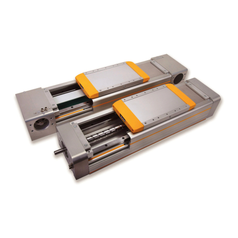
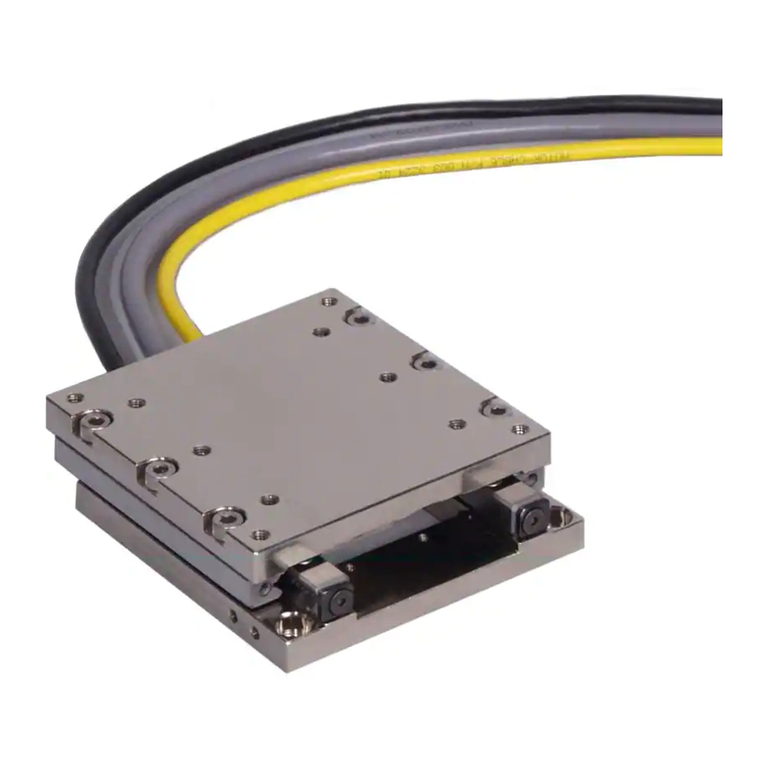
Parker Daedal 400LXR Series User manual

Manual No. 100-5319-01
Rev. 3
404LXR Series
Product Manual
Effective: April 11, 2003
Supersedes:
Electromechanical
Positioning Systems
Automation
Daedal

404LXR Series Product Manual
2
Important User Information
The information in the product manual, including any apparatus, methods, techniques, and concepts
described herein, are the proprietary property of Parker Hannifin Corporation, Daedal Division or its
licensors, and may not be copied, disclosed, or used for any purpose not expressly authorized by the
owner thereof.
Since Parker Hannifin Corporation, Daedal Division constantly strives to improve all of its products, we
reserve the right to change this product manual and equipment mentioned therein at any time without
notice.
For assistance contact:
Parker Hannifin Corporation
Daedal Division
1140 Sandy Hill Road
Irwin, PA 15642
Phone: 724/861-8200
800/245-6903
Fax: 724/861-3330
Web site: www.daedalpositioning.com

404LXR Series Product Manual
3
404LXR Series Product Manual
Table of Contents
REVISION NOTES.............................................................................................................................................................. 4
CHAPTER 1 - INTRODUCTION ......................................................................................................................................... 5
PRODUCT DESCRIPTION...................................................................................................................................................... 5
UNPACKING ....................................................................................................................................................................... 5
RETURN INFORMATION........................................................................................................................................................ 6
REPAIR INFORMATION ......................................................................................................................................................... 6
WARNINGS AND PRECAUTIONS ............................................................................................................................................ 6
SPECIFICATION CONDITIONS AND CONVERSIONS ................................................................................................................... 7
ASSEMBLY DIAGRAMS ........................................................................................................................................................ 8
Strip Seal Version............................................................................................................................................................................8
Hardcover Version...........................................................................................................................................................................9
CHAPTER 2 - 404LXR SERIES TABLE SPECIFICATIONS............................................................................................ 10
ORDER NUMBER NOMENCLATURE ..................................................................................................................................... 10
DIMENSIONAL DRAWINGS.................................................................................................................................................. 11
GENERAL TABLE SPECIFICATIONS...................................................................................................................................... 12
404LXR SERIES TECHNICAL DATA .................................................................................................................................... 17
Force/Speed Charts.......................................................................................................................................................................17
Clean Room Preparation ...............................................................................................................................................................18
ELECTRICAL SPECIFICATIONS ............................................................................................................................................ 19
CABLING AND WIRING DIAGRAMS....................................................................................................................................... 21
Connector Pin Out and Extension Cable Wire Color Codes ...........................................................................................................21
CHAPTER 3 - HOW TO USE THE 404LXR ..................................................................................................................... 24
MOUNTING SURFACE REQUIREMENTS ................................................................................................................................ 24
MOUNTING METHODS ....................................................................................................................................................... 24
SIDE AND INVERTED MOUNTING CONCERNS........................................................................................................................ 25
SETTING TRAVEL LIMIT SENSORS ...................................................................................................................................... 25
SETTING HOME SENSOR ................................................................................................................................................... 26
Z CHANNEL POSITION REFERENCE .................................................................................................................................... 26
GROUNDING / SHIELDING .................................................................................................................................................. 26
CABLING ......................................................................................................................................................................... 27
CHAPTER 4 - PERFORMANCE....................................................................................................................................... 28
ACCELERATION LIMITS ...................................................................................................................................................... 28
SPEED LIMITS .................................................................................................................................................................. 29
ENCODER ACCURACY AND SLOPE CORRECTION.................................................................................................................. 29
THERMAL EFFECTS ON ACCURACY..................................................................................................................................... 31
THERMAL EFFECTS ON REPEATABILITY............................................................................................................................... 32
CAUSES OF TEMPERATURE INCREASES .............................................................................................................................. 32
COMPENSATING FOR THERMAL EFFECTS ............................................................................................................................ 33
CHAPTER 5 - CONNECTING THE GEMINI AMPLIFIER................................................................................................. 34
CHAPTER 6 - MAINTENANCE AND LUBRICATION ...................................................................................................... 37
INTERNAL ACCESS PROCEDURE ........................................................................................................................................ 37
SQUARE RAIL BEARING LUBRICATION................................................................................................................................. 39
CABLE MANAGEMENT MODULE REPLACEMENT.................................................................................................................... 39
LIMIT AND HOME SENSOR MODULE ADJUSTMENT ................................................................................................................ 41
LIMIT AND HOME SENSOR MODULE REPLACEMENT.............................................................................................................. 42
APPENDIX A – UNDERSTANDING LINEAR MOTORS.................................................................................................. 43
THE LINEAR MOTOR CONCEPT .......................................................................................................................................... 43
LINEAR MOTOR BENEFITS ................................................................................................................................................. 43
SLOTLESS LINEAR MOTOR DESIGN .................................................................................................................................... 43
ADVANTAGES/DISADVANTAGES OF SLOTLESS LINEAR MOTORS ............................................................................................ 44
APPENDIX B - INTERNAL PROTECTION....................................................................................................................... 45
INDEX ............................................................................................................................................................................... 47

404LXR Series Product Manual Revision Notes
4
Revision Notes
Rev 3 April 11, 2003
Correction for Motor Wire 4 Pin Mat-N-Lok - p. 21
Limit and Home Sensor Module Adjustment Switch positions corrected. – p. 41

404LXR Series Product Manual Chapter 1 - Introduction
5
Chapter 1 - Introduction
Product Description
404LXR Positioner
The 404LXR is a slotless, brushless linear servo motor/square rail bearing positioner housed within
ahigh strength, extruded aluminum body with magnetically retained protective seals. The
positioner is powered by a single rail of high energy rare earth magnets. Load bearing members
provide heavy load and moment capacity, dynamic stiffness and precise straightness and flatness
of travel. The positioner’s integral linear encoder provides high precision, non-contact positional
feedback with selectable resolutions from 0.1 to 5.0 microns. The positioner is also offered with
inductive proximity limit & home sensors, a “Quick Connect”, extended life, and a cable transport
system.
Unpacking
Unpacking
Carefully remove the positioner from the shipping crate and inspect the unit for any evidence of
shipping damage. Report any damage immediately to your local authorized distributor. Please save
the shipping crate for damage inspection or future transportation.
Incorrect handling of the positioner may adversely affect the performance of the unit in its
application. Please observe the following guidelines for handling and mounting of your new
positioner.
•DO NOT allow the positioner to drop onto the mounting surface. Dropping the positioner can generate
impact loads that may result in flat spots on bearing surfaces or misalignment of drive components.
•DO NOT drill holes into the positioner. Drilling holes into the positioner can generate particles and
machining forces that may effect the operation of the positioner. Daedal will drill holes if necessary;
contact your local authorized distributor.
•DO NOT subject the unit to impact loads such as hammering, riveting, etc. Impacts loads generated by
hammering or riveting may result in flat spots on bearing surfaces or misalignment of drive components.
•DO NOT lift the positioner by cables or cable management system. Lifting postioner by cables or cable
management system may effect electrical connections and/or cable management assembly. The unit
should be lifted by the base structure only.
•DO NOT push in magnetically retained strip seals when removing positioner from shipping crate.
Damaging strip seals may create additional friction during travel and may jeopardize the ability of the
strip seals to protect the interior of the positioner.
•DO NOT submerge the positioner in liquids.
•DO NOT disassemble positioner. Unauthorized adjustments may alter the positioner’s specifications and
void the product warranty.

404LXR Series Product Manual Chapter 1 - Introduction
6
Return Information
Returns
All returns must reference a “Return Material Authorization”, (RMA),number. Please call your local
authorized distributor or Daedal Customer Service Department at 800-245-6903 to obtain a “RMA”
number. See Daedal Catalog #8080/USA, page D34, for additional information on returns and
warranty.
Repair Information
Out-of-Warranty Repair
Our Customer Service Department repairs Out-of-Warranty products. All returns must reference a
“RMA” number. Please call your local authorized distributor or Daedal Customer Service
Department at 800-245-6903 to obtain a “RMA” number. You will be notified of any cost prior to
making the repair.
Warnings and Precautions
Hot Surfaces
DO NOT touch ‘carriage forcer’, (see page 7, Assembly Diagram,for component location), after
high duty operation. Unit may be too HOT to handle.
Electrical Shock
DO NOT take apart or touch any internal components of the positioner while unit is plugged into an
electrical outlet. SHUT OFF power before replacing components to avoid electrical shock.
High Magnetic Field
Unit may be HAZARDOUS to people with Pace Makers or any other 'magnetically-sensitive'
medical devices. Unit may have an effect on 'magnetically-sensitive' applications.
Ferrous Materials
The positioner's 'protective seals' MAY NOT keep out all small ferrous materials in applications with
air born metallic particles. The customer must take additional precautions in these applications to
keep positioner free of these highly magnetic particles.
Vertical Operation
The 404LXR is NOT recommended for vertical operation. The carriage and customer's load will fall
in power loss situations potentially causing product damage or personal injury.
General Safety
Because linear motors can accelerate up to 5 g's, and sometimes positioners move without
warning, keep all personnel away form dynamic travel range of positioner.

404LXR Series Product Manual Chapter 1 - Introduction
7
Specification Conditions and Conversions
Specifications are Temperature Dependent
Catalog specifications are obtained and measured at 20 Degrees C. Specifications at any other
temperature may deviate from catalog specifications. Minimum to maximum continuous operating
temperature range (with NO guarantee of any specification except motion) of a standard unit before
failure is 5 - 40 Degrees C.
Specifications are Mounting Surface Dependent
Catalog specifications are obtained and measured when the positioner is fully supported,bolted
down (to eliminate any extrusion deviation), and is mounted to a work surface that has a maximum
flatness error of 0.013mm/300mm (0.0005”/ft).
Specifications are Point of Measurement Dependent
Catalog specifications and specifications in this manual are measured from the center of the
carriage, 38 mm above the carriage surface. All measurements taken at any other location may
deviate from these values.

404LXR Series Product Manual Chapter 1 - Introduction
8
Assembly Diagrams
Strip Seal Version

404LXR Series Product Manual Chapter 1 - Introduction
9
Hardcover Version

404LXR Series Product Manual Chapter 2 - 404LXR Series Table Specifications
10
Chapter 2 - 404LXR Series Table Specifications
Order Number Nomenclature

404LXR Series Product Manual Chapter 2 - 404LXR Series Table Specifications
11
Dimensional Drawings

404LXR Series Product Manual Chapter 2 - 404LXR Series Table Specifications
12
General Table Specifications
Specifications
Motor Model 8 Pole
Rated Load 45 kg
Maximum Acceleration 5 Gs
Maximum Velocity
Resolution: 0.1 um
0.5 um
1.0 um
5.0 um
0.3 m/sec
1.5 m/sec
3.0 m/sec
3.0 m/sec
Positional Repeatability
Resolution: 0.1 um
0.5 um
1.0 um
5.0 um
+/- 1.0 um
+/- 1.0 um
+/- 2.0 um
+/- 10.0 um
Maximum Force (Peak) 180 N
40 lb.
Maximum Force (Continuous) 50 N
11 lb.
Carriage Weight 1.4 kg
Travel Dependent Specifications
Accuracy*
Positional
Travel
(mm) 0.1, 0.5, 1.0
resolution (um)
5.0 resolution
(um)
Straightline
Accuracy*
(um)
Strip Seal
Version Unit
Weight (kg)
Hard Cover
Version Unit
Weight (kg)
50 6 16 6 4.4 4.4
100 7 17 7 4.8 4.9
150 8 18 9 5.2 5.4
200 10 20 11 5.6 5.8
250 12 22 14 6.0 6.3
300 14 24 17 6.4 6.7
350 16 26 19 6.8 7.2
400 18 28 22 7.2 7.6
500 21 31 26 8.0 8.6
600 25 35 31 8.9 9.5
700 28 38 35 9.7 10.5
800 31 41 39 10.6 11.4
900 33 44 43 11.5 12.5
1000 35 45 47 12.4 13.6
*Accuracy stated is at 20 degrees C, utilizing slope correction factor provided.

404LXR Series Product Manual Chapter 2 - 404LXR Series Table Specifications
13
404LXR Series Technical Data
The useful life of a linear table at full catalog specifications is dependent on the forces acting upon it. These forces include both
static components resulting from payload weight, and dynamic components due to acceleration/deceleration of the load. In
multi-axes applications, the primary positioner at the bottom of the stack usually establishes the load limits for the combined
axes. When determining load/life, it is critical to include the weight of all positioning elements that contribute to the load
supported by the primary axis. The life/load charts are used to establish the table life relative to the applied loads.
404LXR CARRIAGE LIFE VS LOAD
1000
10000
100000
1 3 5 7 9 11 13 15 17 19 21 23 25 28 30 32 34 36 38 40 42 44 46 48 50
LOAD (KG)
LIFE (KM)
NORMAL LOA D CONTINOUS 55 (N)
NORMA L L OA D CONTINUOS 28 ( N)
SIDE L OA D CONTINUOS 5 5( N)
SIDE LOA D CONTINUOUS 2 8 ( N)
BEARING LIFE NORM AL LOAD
1000
10000
100000
10 20 30 40 50 60 70 80 90 100 110 120 130 140 150
NORMAL LOAD PER BEARING (N)
BEARING LIFE (KM)
55(N) CONTINOUS
28 (N) CONTINUOS
Table Load Chart
The “Table Load” chart is
intended to provide a rough-
cut evaluation “life/load”
characteristics of the carriage
support bearings. This curve
is based on the applied load
being centered on the
carriage, normal to the
carriage mounting surface.
Bearing Load Chart
The “Bearing Load” chart
is to be used in conjunction
with the corresponding
formulas on the following
pages to establish the life/load
for each bearing (4 per table).
Several dimensions and the
load geometry are required
for these computations. The
dimensions are referenced
below.

404LXR Series Product Manual Chapter 2 - 404LXR Series Table Specifications
14
Note: 55 (N) continuous is the life rating if the table is operated with a motor thrust force of 55 Newtons
(RMS). The reason that continuous motor force effects bearing life is due to forces applied to the bearing
caused by thermal expansion of the carriage. The 28 (N) rating is the life if only 28 Newtons (RMS) is used.
d1 d2 da
Strip Seal Model 108.5 60.0 48.5
Hardcover
Model 108.5 60.0 53.5
BEARING LIFE SIDE LOAD
1000
10000
100000
10 20 30 40 50 60 70 80
SIDE LOAD PER BEARING (N)
LIFE PER BEARING (KM)
55( N) CONTINUOS"
28(N) CONTINOUS
Side Bearing Load
Chart
The “Side Bearing Load”
chart is to be used in
conjunction with the
corresponding formulas on
the following pages to
establish the life/load for each
bearing (4 per table). Several
dimensions and the load
geometry are required for
these computations. The
dimensions are referenced
below.

404LXR Series Product Manual Chapter 2 - 404LXR Series Table Specifications
15

404LXR Series Product Manual Chapter 2 - 404LXR Series Table Specifications
16
Table A – Linear Motion Guide Bearing Life/Load Computation
Positioner Loads Compute Evaluate Life On
Side & tension Ps > Pt
Side & tension Ps Pt
Pe = (0.5 x Pt) + Ps
Pe = (0.5 x Ps) + Pt
Side load chart
Tension chart
404LXR
Side & compression Ps > Pc
Side & compression Ps Pc
Pe = (0.5 x Pc) + Ps
Pe = (0.5 x Ps) + Pc
Side load chart
Compression chart
Example Computations
Page 14 shows this
configuration with dimensions
given here.
9.14
22
4
21 =
== d
d
L
PP (tension) Kgf
d1 = 108.5 mm
db = 130 mm
d2 = 60.0 mm
d3 = 50 mm
da = 48.5 mm
d4 = da + db = 178.5
9.14
22
4
43 =
== d
d
L
PP (compression) Kgf
8.4
24 1
3
31 =
+== d
d
LL
PP ss
2.0
24 1
3
42 =
== d
d
LL
PP ss
The normal and side force
components on each bearing
block are computed from the
equations as shown:
Life for each bearing needs to be evaluated
independently. For bearings with a side load,
refer to the combined equivalent loading factors
(Table A above).
Example:
Bearing 3 had P3=5.6 Kgf tension and P3s = 2.7
Kgf side load
KgfPcPsPePcPs 7) 5.0(
=
+
×
=
Refer to Bearing Life Normal Load (page 12)
Life @ 7 Kgf (69 Newtons) = 4200 km
Example 1
Horizontal Translation
with Side Loads, 404LXR-
8Pole Positioner
L = 10 Kgf
130 mm from
carriage surface;
50 mm from carriage
center.

404LXR Series Product Manual Chapter 2 - 404LXR Series Table Specifications
17
404LXR Series Technical Data
Force/Speed Charts
The chart on this page illustrates the characteristics of the 404LXR linear motor. The force/speed chart
shows the characteristics of the motor with either a 170 VDC or 340 VDC bus voltage.
Peak
Peak
Continuous
Continuous

404LXR Series Product Manual Chapter 2 - 404LXR Series Table Specifications
18
Clean Room Preparation
404LXR tables with clean room preparation were tested in Daedal’s vertical laminar flow work station which
utilizes ULPA filters to produce an environment having a cleanliness of class 1 prior to testing. Tables were
tested in a variety of orientations with sampling both below the table and at the carriage mounting surface.
Laminar flow rate is 0.65 inches W.C.
Standard Clean Room Preparation
Stringent cleaning and handling measures
Clean room rated lubricant
Strip seal replaced with hard shell cover

404LXR Series Product Manual Chapter 2 - 404LXR Series Table Specifications
19
Electrical Specifications
Parameter 8 Pole Units
Continuous Force 150 N
Continuous Current 1,4,8 2.3 Amps Peak
Continuous Current 1,7 2.0 Amps DC
Peak Force 6180 N
Peak Current 4,6,8 8.3 Amps Peak
Peak Current 6,7 7.2 Amps DC
Voltage Constant 3,4 25.15 Volt/m/sec
Force Constant 921.78 N/Amps Peak
Force Constant 3,4 25.15 N/Amps DC
Resistance 310.2 Ohms
Inductance 52.63 mH
Maximum Bus Voltage 340 Volts DC
Thermal Resist. Winding-Ambient 1 C/watt
Viscous Damping 6.3 N/m/s
Static Friction 1315 N
Intermit Force Duration 10 12 Seconds
Peak Force Duration 115Seconds
Magnetic Attraction 2280 N
Electrical Pitch 12 42 mm
Mass-Motor Carriage 1.5 Kg
Rated Winding Temp. 90 C/watt
Winding Class H -
1. @ 25oCambient, 90oCwinding temperature
2. Measured with a 0.70 mm gap
3. Measured line to line +/-10%
4. Value is measured peak of sine
5. +/-30% line to line, inductance bridge measurement @1Khz
6. Initial winding temperature must be 60oCor less before peak current is
applied
7. DC current through a pair of motor phases of a trapezoidal (six state)
commutated motor
8. Peak of the sinusoidal current in any phase for a sinusoidal commutated
motor
9. Total motor force per peak of the sinusoidal amps measured in any phase,
+/-10%
10. Maximum time duration with 2 times rated current applied with initial winding
temperature at 60oC
11. Maximum time duration with 3 times rated current applied with initial winding
temperature at 60oC
12. The distance from the leading edge of the north pole to the leading edge of
the next north pole
13. Average friction over total table travel
Encoder Specifications
Description Specification
Input Power 5 VDC +/-5% 150 mA
Output (Incremental) Square wave differential line driver (EIA RS422) 2 channels A and B in
quadrature (90) phase shift.
Reference (Z Channel) Synchronized pulse, duration equal to one resolution bit. Repeatability of
position is unidirectional moving toward positive direction.
Maximum Speed 5.0 micron resolution = 3.0 meters/sec
1.0 micron resolution = 3.0 meters/sec
0.5 micron resolution = 1.5 meters/sec
0.1 micron resolution = 0.3 meters/sec
Hall Effect Specification
Description Specifications
Input Power +5 to +24 VDC, 30 mA
Output Open collector, Current Sinking, 20 mA Max

404LXR Series Product Manual Chapter 2 - 404LXR Series Table Specifications
20
Gemini Drive Specifications
Description Specification
Drive Input Power
Voltage
Phase
Frequency
24V Keep Alive (Optional)
96-265 VAC
1Ø
50/60 Hz
24 VDC – 20%
Drive Output Power
Bus Voltage
Switching Frequency
Continuous Current
Peak Current
Commutation
170 or 340 VDC
8or 16 kHz
4.5 Amps
11.25 Amps
Sinusoidal
Command Inputs
Velocity and Torque
Position Mode
Encoder Track Mode
+/-10V
Step & Direction or CW & CCW
Allows post quadrature encoder to be used as command signals
Inputs
Enable (Required)
Reset
Pos/Neg Limits
User Faults
0-24 VDC
Outputs
Fault
At Limit
Position Error
Analog Monitors
Relay
Open collector, 300 mA sink capability
+/-10V scalable, 8 bit (not to be used as control functions)
Normally open, dry contact
Communications
Type
Baud Rate
Daisy Chain
RS232/RS485 (4 wire)
Fixed at 9600
Up to 98
Environmental
Temperature
Humidity
Shock/Vibration
Still air 32oF(0oC)-113oF(46oC), moving air: 32oF(0oC)-122oF(50oC)
0–95%, non-condensing
Shock: 15G half-sign @ 11 msec/vibration: 2G, 10-2000 Hz
Protection
Short Circuit
Brownout
Over Temperature
Phase-to-phase, phase-to-ground
AC drops below 85 VAC
Shutdown fault at 131oF(55oC)
Standards UL, cUL, CE (LVD), CE (EMC)
Limit and Home Sensor Specifications
Description Specification
Input Power +5 to +24 VDC 60 mA
Output Output form is selectable with product:
Normally Closed Current Sinking
Normally Open Current Sourcing
Normally Closed Current Sourcing
Normally Open Current Sourcing
All types Sink or Source maximum of 50 mA
Repeatability Limits: +/- 5 microns (unidirectional)
Home: See Z channel specifications
Table of contents
Other Parker Valve Positioner manuals

Parker
Parker 406LXR Series User manual

Parker
Parker MSR Series Owner's manual

Parker
Parker MSR Series Owner's manual

Parker
Parker MX80S Series User manual

Parker
Parker MX80L series User manual

Parker
Parker 404XE Series User manual

Parker
Parker 404 User manual

Parker
Parker 401XE Series User manual

Parker
Parker 401XR Series User manual

Parker
Parker 404LXR Series User manual
Popular Valve Positioner manuals by other brands

Dresser
Dresser Universal RAI Installation operation & maintenance

TLV
TLV CV10 instruction manual

AUMA
AUMA Matic Series Calibration Instruction

metso automation
metso automation IMO-596 Installation maintenance and operating instructions

GEM
GEM 533 operating instructions

Samson
Samson 4763 Mounting and operating instruction