LevelOne FVT-5000 User manual

FVT-5000
16-Slot Managed Converter Chassis
w/ Redundant Power Supply
User Manual
Ver 1.00 - 0701

Table of Contents
1. INTRODUCTION..................................................................................................................1
1.1. FEATURES .....................................................................................................................1
1.2. SOFTWARE FEATURE......................................................................................................2
1.3. MANAGEMENT METHODS................................................................................................3
1.3.1. Console and Telnet..................................................................................................3
1.3.2. Web-based ..............................................................................................................3
1.3.3. SNMP Network........................................................................................................3
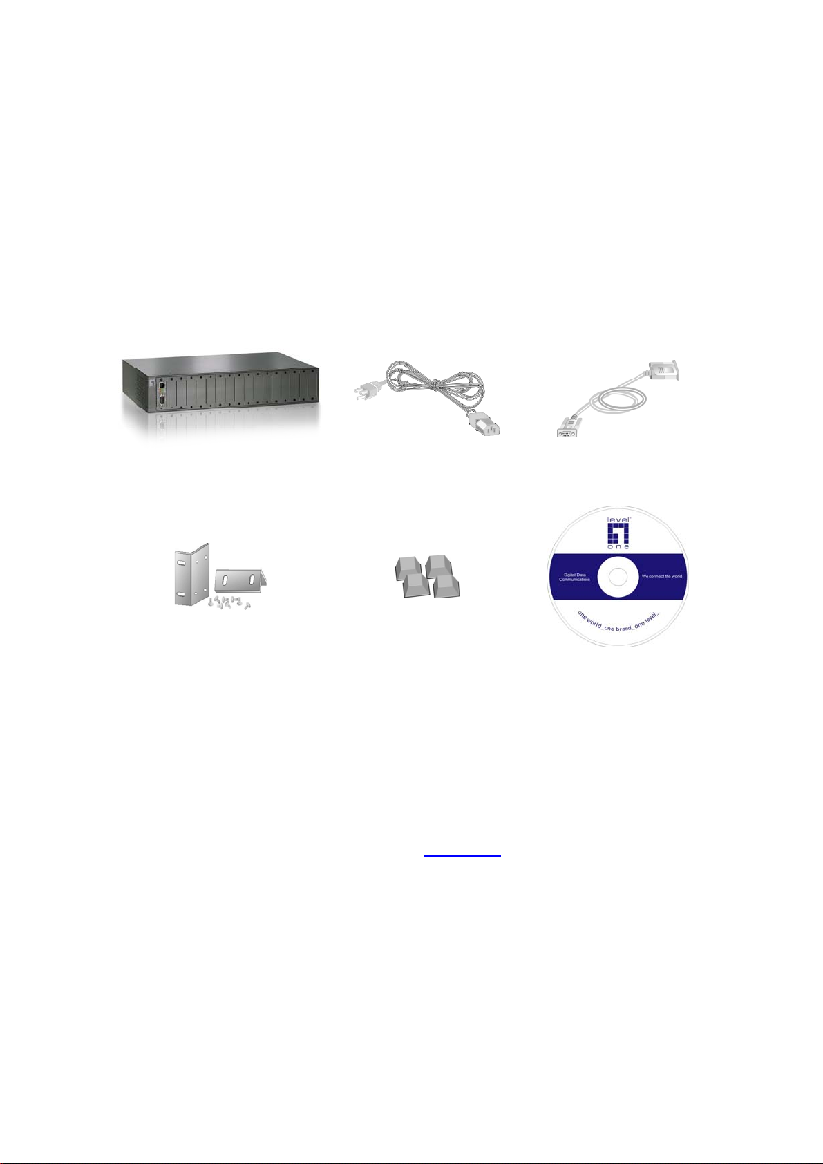
1.4. PACKAGE CONTENTS......................................................................................................4
2. HARDWARE DESCRIPTION...............................................................................................5
2.1. FRONT PANEL................................................................................................................5
2.2. REAR PANEL..................................................................................................................5
2.3. LED INDICATORS ...........................................................................................................6
3. CONNECTING TO THE NETWORK.................................................................................... 7
3.1. PRE-INSTALLATION REQUIREMENTS ................................................................................7
3.2. MOUNTING THE DEVICE ..................................................................................................8
3.2.1. Desktop Installation .................................................................................................8
3.2.2. Rack Mounting.........................................................................................................9
3.3. POWER ON..................................................................................................................10
3.4. DIAGNOSTIC TEST........................................................................................................10
3.4.1. Connecting the Device via Local console..............................................................10
3.4.2. Connecting the Device via Telnet..........................................................................12
3.4.3. Connecting the Device via Web Browser..............................................................13
4. CONSOLE MANAGEMENT...............................................................................................14
4.1. DEVICE SETTING ..........................................................................................................14
4.2. MODULES SETTINGS.....................................................................................................16
4.3. REDUNDANT POWER STATUS........................................................................................18
4.4. EVENTS LOG................................................................................................................18
4.5. SNMP TRAP................................................................................................................19
4.6. SECURE IP FOR TELNET,HTTP AND SNMP..................................................................19
4.7. PORT COUNTERS .........................................................................................................20
4.8. FAN STATUS ................................................................................................................20
4.9. SAVE CURRENT SETTINGS............................................................................................20
4.10. FACTORY DEFAULT SETTINGS &REBOOT SYSTEM.........................................................21
4.11. REBOOT SYSTEM .........................................................................................................21
4.12. TFTP CONFIGURATION.................................................................................................21
5. WEB-BASED MANAGEMENT ..........................................................................................22
5.1. HOME..........................................................................................................................23
5.2. MODULES SETTINGS.....................................................................................................25
5.2.1. Module...................................................................................................................25
5.2.2. TS-1000 setting: ....................................................................................................26
5.2.3. RJ-45 Port..............................................................................................................30
5.2.4. Fiber Port...............................................................................................................30
5.3. PORT COUNTER ...........................................................................................................31
5.4. IP CONFIG ...................................................................................................................32
5.5. SNMP.........................................................................................................................33
5.6. EVENT LOG..................................................................................................................34
5.7. MISC SETTINGS............................................................................................................35
5.8. SAVE AND REBOOT.......................................................................................................38
5.9. UPGRADE ....................................................................................................................39
5.10. HELP ...........................................................................................................................39
6. SNMP MANAGEMENT......................................................................................................40
7. SPECIFICATION................................................................................................................ 41
8. OPTIONAL MODULE.........................................................................................................42
8.1. MODULE (TS-1000) FOR FVT-5000 ONLY....................................................................42
8.2. CONVERTER (TS-1000) ...............................................................................................42

1
1. Introduction
The FVT-5000 16 Slots Managed Converter Chassis is a combination of 16-slot
host cabinet and optional several of media converter bracket modules. A
maximum 16-bracket module can be installed in the cabinet with two redundant
power supplies. The Power supply supports AC input type with load sharing
redundant feature. The converter supports TS-1000 standard that provides loop
back test to ensure the converter failure and remote configuration allows remote
set up the module of the converter or the converter.
With build-in Web-based Management, Managing and Configuring the 16 Slots
Managed Converter Chassis becomes easier. From cabinet management to
each bracket module, user can visually configure and manage your network via
Web Browser. The 16 Slots Managed Converter Chassis can also be managed
via Telnet, Console, or third-party SNMP Management.
1.1. Features
16 slots converter chassis
Redundant AC power supply
HTTP, Telnet security
IP address security for management station
Web and TFTP firmware upgrade
Link Lost Forwarding (LLF)
Back-door password supported
Module identification
Fiber Module hot-swappable
CPU module hot-swappable
SNMP, Web, Telnet, console management
Optional different converter modules
10/100TX to 100FX module
1000T to SFP fiber module
Support TS-1000 on 10/100TX to 100FX module
Event log and SNMP Trap supported
SNMP MIB II and private MIB supported
Support Simple Network Time Protocol (SNTP)
Power and Fan Detect
Loop Back Test
EIA RS-310C 19 “ standard

2
1.2. Software Feature
Management Telnet
Web
Console (RS-232)
Web/Telnet Can be enabled or disabled
MIBS RFC 1213 MIB II
Private MIB
SNMP Trap
Link down
Link up
Power module status change
Authorization Fail
Module plug in and plug out
Chassis configuration change
Module configuration change
Software Upgrade Firmware upgrade by Web interface and TFTP
Link Loose
Forward
Each module support LLF feature. It can be set by Web or CLI menu
LLF Mode TX →Fiber: UTP port link down,
the fiber port will be forced down
LLF Mode Fiber →UTP : Fiber port link down,
the UTP port will be forced down
Packet counter
UTP port: IN-good / In-bad packet counter
out-good /out-bad packet counter
collision counter
Fiber port: IN-good / In-bad packet counter
out-good /out-bad packet counter
SNMP Trap Node Up to 4 Trap node
IP security IP security for telnet
HTTP and SNMP access
Up to 4 IP nodes when security is enabled
Module Note Per module can added notice for allocate information and characters
which is up to 32
Back-door password Supports on CLI mode only
TS-1000 Loop back test, remote configuration
SNTP RFC2030 Simple Network Time Protocol
Events log Up to 4095 event records. It can be reviewed by CLI and Web
browser mode

3
1.3. Management Methods
The FVT-5000 Managed Converter Chassis supports following management
methods:
1.3.1. Console and Telnet
Console Management is done through the RS-232 Console Port that requires a
direct connection between PC and the Device. The Telnet management is
through the network. Once the Device is on the network, you can use Telnet
program to Log in and modify the configuration.
1.3.2. Web-based
The 16 Slots Managed Converter Chassis provides an embedded HTML web
program in flash memory. It offers advanced management features and allow
users to manage the 16 Slots Managed Converter Chassis from anywhere on
the network through any HTTP browser such as Microsoft Internet Explorer. For
more information, see Section 5 Web-Based Management.
1.3.3. SNMP Network
SNMP (Simple Network Management Protocol) provides a way to monitor and
control network device, such as configurations, statistic collection, performance,
and security.
Data is collected by SNMP agents, which are hardware & software processes
reporting activity in each network device. The agent reports information
contained in a MIB format (Management Information Base), which is a data
structure that defines what is obtainable from the device and what can be
controlled.

4
1.4. Package Contents
Unpack the carton of the 16 Slots Managed Converter Chassis and verify them
against the checklist below:
- FVT-5000
- Power Cord
- Console cable
- Rack-mount Kit
- Four Rubber Pads
- User Manual
FVT-5000 Power Cord Console cable
Rack-mount Kit Rubber Pads CD User Manual
Compare the contents of your 16 Slots Managed Converter Chassis package
with the standard checklist above. If any item is missing or damaged, please
contact the local dealer for service.
Note:
Modules are not included. Please refer to Chapter.8 for more information

5
2. Hardware Description
The 16 Slots Managed Converter Chassis is a modular unit that contains 16
slots and 2 power slots. All optional models come with the built-in CPU, and the
RS-232 port is used for Out-of-Band Management and one Ethernet RJ-45
connector is for In-band management that both in front panel. This section
mainly describes the hardware of the 16 Slots Managed Converter Chassis and
gives a physical and functional overview on certain module converter.
The physical dimensions of the 16 Slots Managed Converter Chassis is
448mm x 279mm x 89mm (Lx W x H)
2.1. Front Panel
The front panel of 16 Slots Managed Converter Chassis with the cabinet and
modules is shown as figure below:
Front Panel (within all modules)
2.2. Rear Panel
The 3-pronged power plug is located at the Rear Panel of the 16 Slots Managed
Converter Chassis as figure shown. The power is AC power in the range of
100-240VAC, 50-60Hz (AC power supply). System can install two units with
same power type. The factory default has two power module units installed.
Rear Panel
Power Slot B with AC Power Module Power Slot A with AC Power Module

6
2.3. LED Indicators
All LED status indicators are located on the front panel of the modules. They
display real-time indication of system and operational status.
CPU Panel
LED Description
LED Status Meaning
CPU Ready Blink (Green) System kernel is working correctly
PWR Green Power on
Green Power Module A Ready
Good A Off Power Module A Not Ready
Green Power Module B Ready
Good B Off Power Module B Not Ready
Orange Power Module A Fail
Fail A Off Power Module A Ready
Orange Power Module B Fail
Fail B Off Power Module B Ready
Green Ethernet port is connected with the device.
LK/ACT Blink The port is receiving or transmitting data
Yellow Ethernet is linked with Full Duplex mode
FDX Blink Collision of Packets occurs in the port.

7
3. Connecting to the Network
This chapter provides the installation procedure.
3.1. Pre-Installation Requirements
Before to start hardware installation, make sure the installation environment has
following items:
PCs with 10/100Base-TX Ethernet cards:
The PC must have a standard Ethernet interface to connect with the
Device.
UTP/STP cable with RJ-45 connector:
Check the cable and connectors work properly.
Fiber cable with SC/LC connector:
Check the cable and connector types are correct.
Power outlet:
100 to 240V AC at 50 to 60 Hz power. Make sure that the Device power is
accessible and cables can be connected easily.
Dedicated power supply:
Use dedicated power circuits or power conditioners to supply reliable
electrical power to the network devices.
A dry cool place:
Keep the device away from moisture. Avoid direct sunlight, heat source,
and high amount of electromagnetic interference around.
Mounting tools:
If user intends to mount the device on a rack, make sure have all the tools,
such as mounting brackets and screws.

8
3.2. Mounting the Device
The 16 Slots Managed Converter Chassis is suitable for an office environment
where it can be rack-mounted in standard EIA 19-inch racks or standalone.
3.2.1. Desktop Installation
Set the device on a sufficiently large flat space with a power outlet nearby. And,
the surface where user put the device should be clean, smooth, level, and sturdy.
Please make sure there is enough spacing around the device to allow attaching
of cables, power cord and air circulation.
Attaching Rubber Pads
Make sure mounting surface on the bottom of the device is grease and dust free
Remove adhesive backing from Rubber Pads
Apply the Rubber Pads to each corner on the bottom of the device. (These
footpads can prevent the device from shock/vibration.)
Attaching Rubber Pads to each corner of the Device’s bottom
Other manuals for FVT-5000
1
Table of contents
Other LevelOne Chassis manuals
Popular Chassis manuals by other brands

Supero
Supero SC846TQ-900B user manual

Supero
Supero SC742i user guide

IEI Technology
IEI Technology PAC-400AI Quick installation guide

National Instruments
National Instruments NI 9147 Getting started guide

National Instruments
National Instruments NI PXI-1006 installation guide

SilverStone
SilverStone SUGO series manual