INTERNAL JUMPER SELECTIONS
Caution: The following procedures should be performed by qualied personnel only.
Remove all power and remove the cover of the dimmer pack. Locate and change conguration DIP swutch
settings on the ring card as indicated in the following section.
Softstart
The Softstart mode of operation forces at least a 1/10th second delay between the output being full OFF to the
output being full ON to allow a more gradual warming of the lamp laments. Thermal shock and inrush currents
are reduced thereby increasing lamp life. Softstart should not be used when quick dimmer response is desired,
such as chasing.
To enable Softstart, remove the jumper block from the pin marked P13 on the ring card. Replacing the jumper
block will disable Softstart. Switch DIP 1 Off.
NOTE: The channels of the DDS 5600 congured for NON DIM operation will not be affected by Softstart.
NON DIM Channels (Relay Mode)
Any of the channels of the DDS 5600 may be congured as NON DIM channels. This will cause the output of the
channel to go to full ON whenever the input signal is over 15%. When the input signal drops to less than 10%,
the channel output goes to full OFF. This is the equivalent of a zero-crossing solid state relay.
To congure a channel for NON DIM operation simply switch the dip switches on the ring card as indicated
below. Moving the switch to ON will restore dimming operation.
AUTO SEQUENCING MODE
The DDS 5600 dimmers can be congured to perform stand alone Automatic Sequencing in place of Auto Lamp
Test. This is useful for lighting displays and show windows. The four channels will automatically fade from one
to another in a preprogrammed pattern and time selected by the front panel DIP switch whenever DIP switch #8
is down and no multiplex signal is detected. The analog control input will continue to operate while the dimmer
is sequencing. Patterns and time settings are set by external dip switches 1-6.
To enable Automatic Sequencing Mode switch DIP 2 Off.
NOTE: Auto sequence will not start unless internal DIP 2 and external DIP 8 are off and control signal
must be absent.
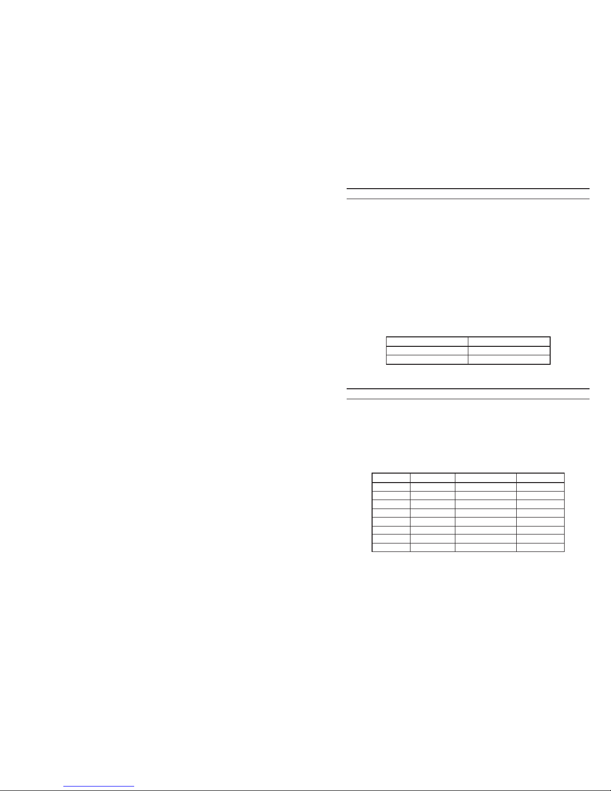
Dip Switch Settings
DIP switch #7 ON causes all above sequences to ping-pong.
Page 2
Table of Contents
INTRODUCTION..................................................................................................................................................... 3
SPECIFICATIONS................................................................................................................................................... 3
MOUNTING............................................................................................................................................................. 3
AC POWER CABLE ...............................................................................................................................................4
AC OUTPUT RECEPTACLES ................................................................................................................................ 4
MICROPLEX MULTIPLEX CONTROL WIRING..................................................................................................... 4
ANALOG 0-10 VDC CONTROL WIRING...............................................................................................................4
DMX512 MULTIPLEX CONTROL WIRING ............................................................................................................5
LED INDICATORS ..................................................................................................................................................5
AUTO LAMP TEST .................................................................................................................................................5
CHANNEL FUSES ..................................................................................................................................................5
INSTALLATION AND OPERATION TIPS............................................................................................................... 5
ADDRESSING.........................................................................................................................................................6
INTERNAL JUMPER SELECTION......................................................................................................................... 7
Softstart........................................................................................................................................................7
NON DIM Channels (Relay Mode) ..............................................................................................................7
AUTO SEQUENCING MODE .................................................................................................................................7
Page 7
STEP TIME SWITCH 1, 2, 3 PATTERN SWITCH 4, 5, 6
1 SECOND OFF, OFF, OFF 2 CHAN BUILD OFF, OFF, OFF
3 SECOND ON, OFF, OFF 3 CHAN SEQUENCE ON, OFF, OFF
5 SECOND OFF, ON, OFF 3 CHAN BUILD OFF, ON, OFF
10 SECOND ON, ON, OFF 2 & 4 CHAN ALT ON, ON, OFF
15 SECOND OFF, OFF, ON 4 CHAN SEQUENCE OFF, OFF, ON
30 SECOND ON, OFF, ON 4 CHAN BUILD ON, OFF, ON
45 SECOND OFF, ON, ON 4 CHAN BUILD + OFF, ON, ON
60 SECOND ON, ON, ON 4 CHAN RANDOM ON, ON, ON
CHANNEL DIP SWITCH CHANNEL DIP SWITCH
1 3 OFF 2 4 OFF
3 5 OFF 4 6 OFF