Leviton OPB15-DW User manual

WARNING: TO AVOID FIRE, SHOCK, OR DEATH; TURN
OFF POWER at circuit breaker or fuse and test that power is
off before wiring!
Preparing and connecting wires:
Make sure the wires from the wall box are straight (cut if
necessary). Remove insulation from each wall box wire and
Sensor Power Base as shown:
Occupancy Sensor Power Base
Cat. No. OPB15
15A @ 120V, 60Hz – Fluorescent/Incandescent
15A @ 277V, 60Hz – Fluorescent
3/4 hp @ 120V, 60Hz
2 hp @ 277V, 60Hz
For use with OSCxx Occupancy Sensors
INSTALLATION INSTRUCTIONS
Mount power base in desired electrical box
application:
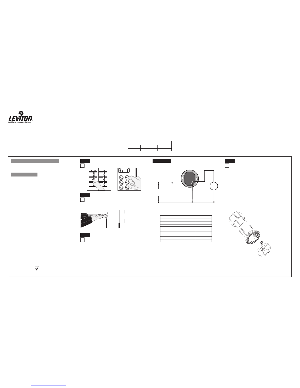
A. To mount inside 4" octagon 2.125" deep ceiling
electrical box, refer to Figure 1. Wire per Step 2.
• Dress line voltage wires to provide enough clearance in electrical
box when device is installed.
• Partially thread the two #8-32 screws provided into mounting
holes of the electrical box.
• Align the power base body so that it fits between the mounting
holes of the electrical box and insert over mounting screws.
• Turn counter clockwise until it reaches the stops.
• Tighten mounting screws firmly.
Tools needed to install your Sensor:
Slotted/Phillips Screwdriver
Pliers
Cutters
Parts Included List:
Sensor Base (1)
#8-32 x 3/4" Screw (2)
#6-32 x 13/16" Screw (2)
FEATURES
• Adapts OSCxx Sensors to line-voltage
• 24VDC Output
• Mounts inside a 2.125" deep octagon or 4" square
Electrical Box (w/mud ring)
DESCRIPTION
The OPB15 adapts Leviton low-voltage ceiling occupancy sensors
to operate on line-voltage electrical systems. Designed to control
up to 15 amps of lighting load from a single occupancy sensor. The
Power Base contains a power supply and a load switching relay. The
power supply provides Class II low-voltage power for OSCxx Series
Occupancy Sensors. The relay in the Power Base is controlled by the
occupancy sensors connected via the control input of the two-part
terminal connector. The Power Base includes zero cross switching
circuitry to minimize inrush current associated with electronic ballasts.
This reduces wear and tear on the relay contacts making the power
pack last longer.
Application Notes:
OPB15 works well where installation of a low-voltage wiring typical
with traditional power packs and sensors is difficult, inconvenient or
costly. It is ideal for existing buildings where access to wiring is limited
or for new construction with line-voltage circuiting only.
LOW-VOLTAGE CURRENT CAPACITY
OPB15 is designed for a single occupancy sensor with a maximum
current capacity of 40mA.
INSTALLING YOUR OCCUPANCY SENSOR POWER
BASE
NOTE: Use check boxes when Steps are completed.
Step 1
WARNINGS AND CAUTIONS:
• To be installed and/or used in accordance with appropriate electrical codes and regulations.
• If you are unsure about any part of these instructions, consult a qualified electrician.
• Sensors must be mounted on a vibration free surface.
5/8"
(1.6 cm)
Strip Gage (measure bare
wire here)
Step 3
Step 2
Figure 1
Ceiling Installation in a 4" Octagon 2.125" Electrical Box
DI-000-OPB15-00A-X3
CATALOG ITEMS
Catalog No.
OPB15-0DW
Power Input
120-277VAC, 60Hz
Power Output
24VDC, 40mA
• Input voltage tolerance 10%
• Output voltage tolerance 15%, Output voltage listed at nominal.
Wiring your Sensor Power Base (Line Voltage):
NOTE: This application is based on the wall box being
pre-installed.
Connect wires per WIRING DIAGRAM as follows: Twist
strands of each lead tightly together and, with circuit
conductors, push firmly into appropriate wire connector.
Screw connectors on clockwise making sure no bare
conductors show below the wire connectors.
Step 4
4" Octagon 2.125" Deep Electrical Box
8-32 Screws
Sensor Power Base
Two-Part Terminal
Connector
Ceiling
Sensor
Hot (Black)
Neutral (White)
Load
Black
White
Black
Blue
White
Line
120/277VAC
60Hz
Sensor Power
Base
All wires rated at 105° C. 600V insulation.
Class II wires are Teflon coated.
Signal Name Color Gauge
Line Voltage Wires
Line 120/277V Black 14AWG
Neutral White 14AWG
Load Blue 14AWG
Class II Two-Part Terminal
Common Black 22AWG
Power (+24VDC) Red 22AWG
Control (Occupancy Sensor) Blue or Gray 22AWG
WIRE DESIGNATIONS
Step 3 cont’d
WARNINGS AND CAUTIONS:
• All sensors must be mounted at least 6 feet away from air vents.
• Disconnect power when servicing fixture or changing lamps.
• Use this device only with copper or copper clad wire. With aluminum wire use
only devices marked CO/ALR or CU/AL.
Cut
(if necessary)

LIMITED FIVE YEAR WARRANTY AND EXCLUSIONS
Leviton warrants to the original consumer purchaser and not for the benefit of anyone else that this product at the time of its sale by Leviton is free of defects in materials and workmanship under normal and proper use for five years from the purchase date. Leviton’s only obligation is to correct such defects by repair or replacement, at its option, if within such
five year period the product is returned prepaid, with proof of purchase date, and a description of the problem to: Leviton Manufacturing Co., Inc., Att: Quality Assurance Department, 59-25 Little Neck Parkway, Little Neck, New York 11362-2591. This warranty excludes and there is disclaimed liability for labor for removal of this product or reinstallation. This
warranty is void if this product is installed improperly or in an improper environment, overloaded, misused, opened, abused, or altered in any manner, or is not used under normal operating conditions or not in accordance with any labels or instructions. There are no other or implied warranties of any kind, including merchantability and fitness of a
particular purpose, but if any implied warranty is required by the applicable jurisdiction, the duration of any such implied warranty, including merchantability and fitness for a particular purpose, is limited to five years. Leviton is not liable for incidental, indirect, special, or consequential damages, including without limitation, damage to, or loss of use
of, any equipment, lost sales or profits or delay or failure to perform this warranty obligation. The remedies provided herein are the exclusive remedies under this warranty, whether based on contract, tort or otherwise.
DI-000-OPB15-00A-X3
Step 6 Sensor Setup:
Refer to sensor Installation Instruction sheet for
complete details.
Step 7 Restore Power:
Restore power at circuit breaker or fuse. INSTALLATION IS
COMPLETE.
OPERATION
Close Relay: When the attached occupancy sensor detects motion, it will
apply +24V to the Occupancy wire causing the relay to close.
B. To mount inside 2.125"x 4"x 4" electrical box with
mud-ring, refer to Figure 2. Wire per Step 2.
• Ensure that conduit/cable entry clamp is located in corner of
electrical box.
• Dress line voltage wires to provide enough clearance in electrical
box when device is installed.
• Install a two-gang mud ring (not included) on electrical box.
• Partially thread the two #6-32 screws provided into the two-gang
mud ring, refer to Figure 2.
• Align the Power Base body so that it fits between the mounting
holes of the electrical box and insert over mounting screws.
• Turn counter clockwise until it reaches the stops.
• Tighten mounting screws firmly.
Mount power base in desired
electrical box application:
Step 4 cont’d
Figure 2
Ceiling Installation in a
2.125"x 4"x 4" Electrical Box
2.125"x4"x4" Electrical Box
8-32 Screws
4" Mud-ring
(2-Gang)
6-32 Screws
Sensor Power
Base
Two-Part Terminal
Connector
Ceiling
Sensor
Ceiling Mounted Sensors:
NOTE: Refer to sensor installation sheet.
• Remove ceiling mount sensor mounting base by aligning arrows and
pulling apart. Refer to sensor Installation Instructions for full
details.
• Remove two-part terminal connector from Sensor Power Base and
wire per sensor Installation Instructions. Refer to Figure 1 and 2.
NOTE: Low-voltage wires should be trimmed approximately in half so the
length can fit in mounting cavity between sensor and Power Base and no
bare wire is exposed at the connectors.
• Plug the two-part terminal connector into the Power Base with the
screws facing up.
• Align mounting indicator arrows on the Power Base and the sensor
body and push on to Power Base and turn clockwise a quarter turn to
secure.
Step 5
NOTE: For existing 1.50" deep electrical boxes, an extension ring
in the same shape and size can be added to allow Sensor Power
Base to fit.
NOTES
Mount Ceiling Sensor to Power Base:
• Lights Flickering
- Lamp has a bad connection.
- Wires not secured firmly with wire connectors.
• Lights do not turn ON
- Circuit breaker or fuse has tripped.
- Lamp is burned out.
- Lamp Neutral connection is not wired.
- Low-voltage miswired. Verify wiring connections per appropriate
Wiring Diagrams.
- Line voltage miswired. Verify wiring connections per appropriate
Wiring Diagrams.
• Light turns ON
- Constant motion. To Test: Adjust sensor; remove motion source. If
unsatisfactory, move sensor.
• Light turns ON too long
- Adjust sensor.
TROUBLESHOOTING
• For technical assistance call us at: 1-800-824-3005
• Visit our website at www.leviton.com
U.S. & Foreign Patents Pending
Copyright© 2006 Leviton Manufacturing Co., Inc.
All Rights Including Trade Dress Rights Reserved
PRODUCT INFORMATION
This equipment has been tested and found to comply with the
limits for a Class A digital device, pursuant to part 15 of the
FCC Rules. These limits are designed to provide reasonable
protection against harmful interference when the equipment
is operated in a commercial environment. This equipment
generates, uses, and can radiate radio frequency energy and, if
not installed and used in accordance with the instruction manual,
may cause harmful interference to radio communications.
Operation of this equipment in a residential area is likely to
cause harmful interference in which case the user will be
required to correct the interference at his own expense.
FCC COMPLIANCE STATEMENT
This manual suits for next models
2
Other Leviton Power Pack manuals