WARNING AND CAUTIONS
• WARNING: TO AVOID DEATH OR SERIOUS PERSONAL INJURY never
push objects of any kind into this product through openings, as they may touch
dangerous voltages.
• WARNING: TO AVOID DEATH OR SERIOUS PERSONAL INJURY never touch
uninsulated wires or terminals unless the wiring has been disconnected at the
network interface.
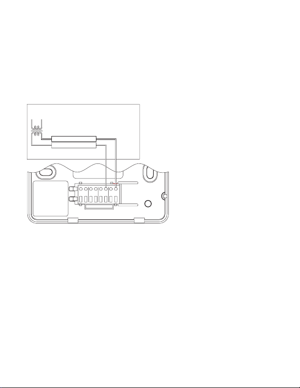
• WARNING: TO AVOID DEATH OR SERIOUS PERSONAL INJURY, be sure
to disconnect the power to the control transformer before removing or installing
thermostat.
• Read and understand all instructions. Follow all warnings and instructions marked
on the product.
• Do not use this product near water - e.g., near a tub, wash basin, kitchen sink or
laundry tub, in a wet basement, or near a swimming pool.
• Never install communications wiring or components during a lightning storm.
• Never install communications components in wet locations unless the components
are designed specifically for use in wet locations.
• Use caution when installing or modifying communications wiring or components.
• SAVE THESE INSTRUCTIONS.
CAUTION:
• Do not short gas valve, fan, heat relay, or cool relay...even momentarily.
• Do not attempt to hook up to live circuits. An accidental connection to a component
on the thermostat circuit board could cause damage to the thermostat.
The following requirements must be observed for installation in Europe: CE
1. This equipment must be installed in accordance with National wiring rules for the
country in which it is installed.
2. All product labels, instructions and markings relating to safety must be translated
to a language, which is acceptable in the country in which this equipment is to be
installed.
1
DESCRIPTION
The RC500-2EW is a precision digital thermostat designed for 24 VAC heating
and cooling systems.
The RC500-2EW will support the following systems:
• Single Stage Heat/Cool Conventional
• Two Stage Conventional (2 Stage Heat / 2 Stage Cool)
• Heat Pump (2 Stage Heat / 1 Stage Cool)
• Two Speed Heat Pump (3 Stage Heat / 2 Stage Cool)
• 2-Pipe and 4-Pipe