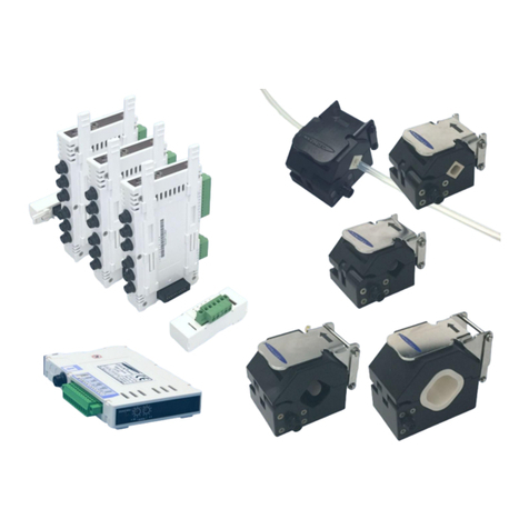
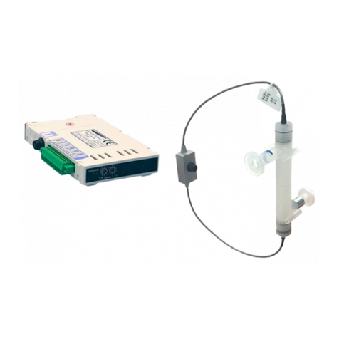
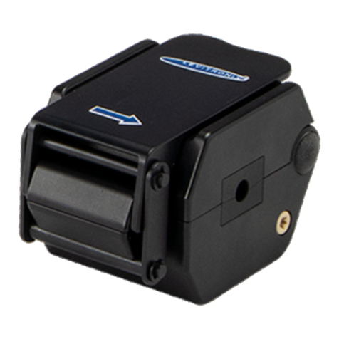
Levitronix LEVIFLOW LFS Series User manual

User Manual for LEVIFLOW®LFS Flowmeters
www.levitronix.com
PL-4502-00, Rev11, DCO# 18-107
First Release: 29-May-09
Last Update: 30-Jul-18
LEVIFLOW®LFS FLOWMETERS
USER MANUAL
LEVIFLOW®Sensors: LFS-04(H), -08(H), -20(H), -50(H), -80(H) (LFS-Series)
LFS-008 (Low-Flow Sensor)
LEVIFLOW®Converters: LFC-1C (single channel, LFS-Series without LFS-008)
LFC-1C-F4 (single channel, LFS-008 only)
LFC-6C (6-channel, LFS-Series without LFS-008)
LFC-6CIO (6-channel, I/O interface, LFS-Series)
This manual contains information necessary for the safe and proper use of the LEVIFLOW®LFS flowmeter series.
Included are specifications for the standard configuration, components, and instructions regarding its use, installation,
operation, adjustment, inspection and maintenance. For special configuration of the LEVIFLOW®flowmeters refer to
accompanying information. If the flowmeters have to be configured for other parameter settings then the LEVIFLOW®
Configuration Software (see relevant manual Levitronix
Doc.# PL-4501-00) is necessary. Please familiarize yourself
with the contents of this manual to ensure the safe and effective use of this product. After reading, please store the
manual where the personnel responsible for operating can readily refer to it at any time.

User Manual for LEVIFLOW®LFS Flowmeters
www.levitronix.com
PL-4502-00, Rev11, DCO# 18-107
2
Table of Contents
1SAFETY PRECAUTIONS ..........................................................................................................................................3
2SPECIFICATIONS .....................................................................................................................................................4
2.1 Component Overview........................................................................................................................................4
2.2 Standard System Configurations.......................................................................................................................6
2.2.1 Single Channel Configuration –LFS-Series .....................................................................................................................6
2.2.2 Multi-Channel Configuration –LFS-Series........................................................................................................................6
2.3 Specifications of Sensors ..................................................................................................................................8
2.4 Specifications of Converters..............................................................................................................................9
2.4.1 General Specifications .....................................................................................................................................................9
2.4.2 Overview of Parameter Configuration.............................................................................................................................10
2.5 Basic Dimensions of Main Components..........................................................................................................11
2.5.1 Dimensions of Sensors ..................................................................................................................................................11
2.5.2 Dimensions of Converters..............................................................................................................................................12
2.5.3 Dimensions of Adaptor Cables.......................................................................................................................................13
3INSTALLATION.......................................................................................................................................................14
3.1 Installation of Converters LFC-1C and LFC-1C-F4..........................................................................................14
3.1.1 Overview and Preparation..............................................................................................................................................14
3.1.2 Instructions for Electrical Installation...............................................................................................................................15
3.1.3 Configuration of Sensor Specific Data............................................................................................................................15
3.1.4 Instructions for Mechanical Installation...........................................................................................................................16
3.2 Installation of Converters LFC-6C and LFC-6CIO ...........................................................................................17
3.2.1 Overview and Preparation..............................................................................................................................................17
3.2.2 Instructions for Electrical Installation...............................................................................................................................19
3.2.3 Configuration of Sensor Specific Data............................................................................................................................19
3.2.4 Instructions for Mechanical Installation...........................................................................................................................20
3.3 Installation of Sensors .....................................................................................................................................21
3.3.1 Overview and Preparation..............................................................................................................................................21
3.3.2 Instructions for Electrical Installation...............................................................................................................................21
3.3.3 Instructions for Mechanical and Hydraulic Installation.....................................................................................................22
4OPERATION............................................................................................................................................................23
4.1 General Timing Specifications.........................................................................................................................23
4.1.1 Startup Time ..................................................................................................................................................................23
4.1.2 Thermal Stability Time....................................................................................................................................................23
4.1.3 Zero Adjustment Activation Time....................................................................................................................................23
4.1.4 Automatic Zero Adjustment duration...............................................................................................................................23
4.2 System Operation with LFC-1C / LFC-1C-F4..................................................................................................24
4.2.1 Standard Operation with PLC Interface ..........................................................................................................................24
4.2.2 Typical Setups Using the PLC Interface .........................................................................................................................24
4.2.3 Operation with RS485....................................................................................................................................................25
4.2.4 Standalone Operation with Display.................................................................................................................................25
4.2.5 Display Messages..........................................................................................................................................................26
4.3 System Operation with Converter LFC-6C and LFC-6CIO..............................................................................27
4.3.1 Standard Operation with PLC Interface (LFC-6CIO only)................................................................................................27
4.3.2 Operation with RS485....................................................................................................................................................27
4.3.3 Standalone Operation with Display.................................................................................................................................27
4.3.4 Display Messages..........................................................................................................................................................27
4.4 Operation with LEVIFLOW®Configuration Software .......................................................................................27
5INSPECTION AND MAINTENANCE .......................................................................................................................28
6TROUBLESHOOTING.............................................................................................................................................29
6.1 Common Troubles...........................................................................................................................................29
6.2 Troubleshooting with LEVIFLOW®Configuration Software..............................................................................29
7TECHNICAL SUPPORT ..........................................................................................................................................29
8APPENDIX...............................................................................................................................................................30
8.1 Regulatory Status............................................................................................................................................30
8.1.1 CE Marking....................................................................................................................................................................30
8.2 Symbols and Signal Words..............................................................................................................................31

User Manual for LEVIFLOW®LFS Flowmeters
www.levitronix.com
PL-4502-00, Rev11, DCO# 18-107
3
1 Safety Precautions
CAUTION
Do not under any circumstances open the converter or sensor housing.
Levitronix does not assume responsibility for any damage, which
occurs under such circumstances.
!
WARNING
Hazardous voltage may be present.
In case of the usage of an inadequate AC/DC power supply, mains
voltages may be present (even if the system is designed for 24VDC).
The converter must be placed in a spill protected environment. Do not
under any circumstances open the powered converter.
The usage of galvanic separated 3rd party tested (like CE and/or UL)
AC/DC supply is highly recommended.
!
WARNING
Toxic chemicals may be present.
When using the flowmeter to measure chemicals skin contact and toxic
gases may be hazardous to your health. Wear safety gloves and other
appropriate safety equipment.

User Manual for LEVIFLOW®LFS Flowmeters
www.levitronix.com
PL-4502-00, Rev11, DCO# 18-107
4
2 Specifications
2.1 Component Overview
Figure 1: Standard LEVIFLOW®LFS flow sensors
Figure 2: Standard LEVIFLOW®LFC converters
Figure 3: LEVIFLOW®accessories
2
1c
3
5
1e
1g
1i
1k
9a
6b
7a
7b
3
4
2
2c
7a
7b
4a
4b
8
1d
1f
6a
9b
9c

User Manual for LEVIFLOW®LFS Flowmeters
www.levitronix.com
PL-4502-00, Rev11, DCO# 18-107
5
Pos.
Part Name
Part #
Shape
Flow
Fitting
(Tube)
Max. Liquid
Temperat.
Cable
Connector
Note
1a
LFS-008-Z / LFS-008-U
100-30323 / 100-30324
Z / U
0 –0.8 lpm
1/4”
90 °C
FEP
0.5 m
PVDF male
connector
cover
Sensor specific
parameter for
converter calibration
are delivered on a tag
attached to the
flowsensor.
1b
LFS-04-Z-T025 / LFS-04-U-T025
100-30321 / 100-30322
Z / U
0 –4 lpm
1/4”
90 °C
1c
1d
LFS-04-Z / LFS-04-U
LFS-04H-Z / LFS-04H-U
100-30304 / 100-30305
100-30330 / 100-30331
Z / U
0 –4 lpm
3/8”
90 °C
180 °C
1e
1f
LFS-08-Z / LFS-08-U
LFS-08H-Z / LFS-08H-U
100-30306 / 100-30307
100-30332 / 100-30333
Z / U
0 –8 lpm
3/8”
90 °C
180 °C
1g
1h
LFS-20-Z / LFS-20-U
LFS-20H-Z / LFSH-20-U
100-30308 / 100-30309
100-30372 / 100-30373
Z / U
0 –20 lpm
1/2”
90 °C
180 °C
1i
1j
LFS-50-Z / LFS-50-U
LFS-50H-Z / LFS-50H-U
100-30310 / 100-30311
100-30340 / 100-30341
Z / U
0 –50 lpm
3/4”
90 °C
180 °C
1k
1l
LFS-80-Z / LFS-80-U
LFS-80H-Z / LFS-80H-U
100-30312 / 100-30313
100-30342 / 100-30343
Z / U
0 –80 lpm
1”
90 °C
180 °C
Table 1: Standard flow sensor models
Pos.
Article Name
Part #
Description
Interfaces
2a
(with 2c)
LFC-1C
100-30314
Single Channel Converter
(Interface connector 2c included)
Analog Output (4 –20 mA), 2x Digital Output, 1x Digital Input, RS485 (MODBUS)
Note: LFC-1C-F4 works with LFS-008 only.
2b
(with 2c)
LFC-1C-F4
100-30325
3
LFC-6C
100-30315
6-Channel Converter
- RS485 (MODBUS)
- Order Bus Conn. (7a) and Terminat. Box (7b) as separate article (see Table 3)
Note: Does not work with LFS-008 sensor.
4
(with 4a
and 4b)
LFC-6CIO
100-30337
6-Channel Converter
with I/O Interfaces
(Digital I/O connector 4a and analog output
connector 4b included)
- RS485 (MODBUS) protocol
- 6 analog outputs (4 –20 mA), 6 digital inputs, 6 digital outputs
- Order Bus Conn. (7a) and Terminat. Box (7b) as separate article (see Table 3)
- EMI ferrite (8) to be ordered as separate article (see Table 3)
Table 2: Standard converters
Pos.
Article Name
Part #
Features
Special Feature
5a
LFE-A.1-10
LFE-A.1-30
LFE-A.1-60
190-10162
190-10163
190-10164
Cable length: 1 m, PVC
Cable length: 3 m, PVC
Cable length: 6 m, PVC
- PP female connector cover for IP-65 chemical protection
- Flame retardant PVC white (UL VW-1 corresponds to EN-60332-1-2)
5b
LFE-A.2-10
LFE-A.2-30
LFE-A.2-60
190-10165
190-10166
190-10167
Cable length 1 m, FEP
Cable length 3 m, FEP
Cable length 6 m, FEP
- PP female connector cover for IP-65 chemical protection
6a
LFE-D.1-10
LFE-D.1-30
LFE-D.1-60
190-10296
190-10297
190-10298
Y cable, 1 m, PVC, cover
Y cable, 3 m, PVC, cover
Y cable, 6 m, PVC, cover
For lFC-6CIO with protective SMB connector PP cover.
6b
LFA-A.1
190-10268
Y adaptor cable, PVC
For LFC-6CIO
7a
Connector Box for LFC-6C
100-30316
COMBICON connector
For wiring RS485 and supply of stacks of LFC-6C and LFC-6CIO converters.
7b
Termination Box for LFC-6C
100-30317
--
For termination of RS485 bus of LFC-6C and LFC-6CIO.
8
LeviFlow Splitting Ferrite
100-30353
EMI filtering of DC supply
For LFC-6CIO supply needed.
9
USB to RS485 Adaptor-TR
Isolated YN-485I-TR
100-30392
Structure/Design
USB connector (9a) with termination resistor and cable with connector pair (9b
and 9c) for external RS485 wire connection. Isolated. Cable length is 2m.
Purpose
Communication over fieldbus of driver with PC
Table 3: Accessories
Pos.
Part Name
Part #
Flow
Range
Fitting
(Tube)
Max. Liquid
Temperat.
Cable
Note
9a
LFS-008-Z + LFC-1C-F4
LFS-008-U + LFC-1C-F4
100-90625
100-90626
0 –0.8 lpm
1/4"
90 °C
FEP
0.5m
Converter is delivered with sensor
specific parameters already stored.
Extension cables to be ordered as
separate article with specified length
(see Table 3).
9b
LFS-04-Z-T025+LFC-1C
LFS-04-U-T025+LFC-1C
100-90627
100-90628
0 –4 lpm
1/4"
90 °C
9c
LFS-04-Z+LFC-1C
LFS-04-U+LFC-1C
LFS-04H-Z+LFC-1C
LFS-04H-U+LFC-1C
100-90604
100-90605
100-90630
100-90631
0 –4 lpm
3/8”
90 °C
90 °C
180 °C
180 °C
9d
LFS-08-Z+LFC-1C
LFS-08-U+LFC-1C
LFS-08H-Z+LFC-1C
LFS-08H-U+LFC-1C
100-90606
100-90607
100-90812
100-90813
0 –8 lpm
3/8”
90 °C
90 °C
180 °C
180 °C
9e
LFS-20-Z+LFC-1C
LFS-20-U+LFC-1C
LFS-20H-Z+LFC-1C
LFS-20H-U+LFC-1C
100-90608
100-90609
100-90835
100-90836
0 –20 lpm
1/2”
90 °C
90 °C
180 °C
180 °C
9f
LFS-50-Z+LFC-1C
LFS-50-U+LFC-1C
LFS-50H-Z+LFC-1C
LFS-50H-U+LFC-1C
100-90621
100-90622
100-90802
100-90714
0 –50 lpm
3/4”
90 °C
90 °C
180 °C
180 °C
9g
LFS-80-Z+LFC-1C
LFS-80-U+LFC-1C
LFS-80-Z+LFC-1C
LFS-80-U+LFC-1C
100-90623
100-90624
100-90715
100-90716
0 –80 lpm
1”
90 °C
90 °C
180 °C
180 °C
Table 4: Flowmeter sets –flowsensor with single channel converter LFC-1C/LFC-1C-F4

User Manual for LEVIFLOW®LFS Flowmeters
www.levitronix.com
PL-4502-00, Rev11, DCO# 18-107
6
2.2 Standard System Configurations
2.2.1 Single Channel Configuration –LFS-Series
Figure 4: Flowmeter configuration with LFC-1C single channel converter
(For LFS-008 flow sensor special LFC-1C-F4 converter is necessary)
2.2.2 Multi-Channel Configuration –LFS-Series
Figure 5: Flowmeter configuration with LFC-6C converter (6 channel)
(Does not work with LFS-008 flow sensor)
LEVIFLOW® Converter LFC-1C
(Single Channel)
4-Digit Display
Zero Adjustment
Adress Setting for RS485
Piezo Transducers
In-/Output
IN OUT Electrical Interface
Power Supply: 24 VDC
RS485 (MODBUS)
- Configuration with PC Software
- Data Reading
- Fieldbus Array of Multiple Sensors
Analog and Digital Outputs
- 1x Analog Output
- 2x Digital Outputs
- 1x Digital Input
LEVIFLOW® Sensor LFS-xx
Flow In
Flow Out
Extension
Cables LFE
Digital
Signal Processor
DSP
LEVIFLOW® Converter LFC-6C
(6-Channel)
4-Digit Display
Zero Adjustment
Address Setting for RS485
Piezo Transducers In-/Output
Signal/Power Bus Connector
Power Supply: 24 VDC
RS485 (MODBUS)
- Configuration with PC Software
- Data Reading
Digital
Signal Processor
DSP
Flowsensor LFS
Flowsensor LFS
Flowsensor LFS
Flowsensor LFS
Flowsensor LFS
Flowsensor LFS
2
1
3
1
5
5

User Manual for LEVIFLOW®LFS Flowmeters
www.levitronix.com
PL-4502-00, Rev11, DCO# 18-107
7
Figure 6: Flowmeter configuration with LFC-6CIO converter (6 channel with I/O interfaces)
LEVIFLOW® Converter LFC-6CIO
(6-Channel with I/O Signals)
4-Digit Display
Zero Adjustment
Address Setting for RS485
Piezo Transducers In-/Output
Signal/Power Bus Connector
Power Supply: 24 VDC
RS485 (MODBUS)
- Configuration with PC Software
- Data Reading
Digital
Signal Processor
DSP
Flowsensor LFS
Flowsensor LFS
Flowsensor LFS
Flowsensor LFS
Flowsensor LFS
Flowsensor LFS
Analog Output
Connector
Digital I/O
Connector
Analog Outputs:
6 Channels
Digital Outputs:
6 Channels
Digital Inputs:
6 Channels
EMI
Ferrite
4
8
1
5
6
4b
4a

User Manual for LEVIFLOW®LFS Flowmeters
www.levitronix.com
PL-4502-00, Rev11, DCO# 18-107
8
2.3 Specifications of Sensors
Sensor Type
Characteristics
LFS-008
LFS-04(H)
LFS-08(H)
LFS-20(H)
LFS-50(H)
LFS-80(H)
Flow Range [lpm]
0 –0.8
0 –4
0 –8
0 –20
0 –50
0 –80
Fitting Tube Size (OD)
1/4”
1/4” or 3/8”
3/8”
1/2”
3/4”
1”
Measurement Path ID in [mm]
2.5
4
6
10
15
20
Accuracy
Flow Velocity < 1 m/s
Flow Range [lpm]
0 –0.035
0 –0.8
0 –1.7
0 –4.7
0 –10.6
0 –18.8
Accuracy [lpm]
see Figure 7
± 0.008
± 0 –0.017
± 0.047
± 0.106
± 0.188
Repeatability [lpm]
see Figure 7
< 0.004
< 0.009
< 0.024
< 0.053
< 0.094
Accuracy
Flow Velocity > 1 m/s
Flow Range [lpm]
0.035 –0.8
0.8 –4
1.7 –8
4.7 –20
10.6 –50
18.8 –80
Accuracy of Reading
± 1%
± 1%
± 1%
± 1%
± 1%
± 1%
Repeatability of Read.
< 0.5%
< 0.5%
< 0.5%
± 0.5%
± 0.5%
± 0.5%
Wetted Surface Area [cm2]
38.3
59.0 (for 3/8”)
61.7
87.5
155.9
233.1
Weight [g]
97
97
95
115
150
180
Pressure Drop Coefficient C
P = C x Q2 ,
Q = Flow [lpm],
P = Press. Drop [kPa]
16.8
1.80 for 3/8”
5.41 for 1/4”
0.88
0.06
0.01
0.003
Maximum Fluid Pressure at 20 / 90 °C in [bar]
5 / 5
5 / 5
5 / 4.1
5 / 4.1
5 / 4.1
5 / 4.1
Fluid Temperature
Normal range: 10 –90 0C ( 50 –194 0F )
For LFS-xxH (high-temp version): 10 - 180 0C (50 - 356 0F)
Ambient Temperature
0 –60 0C (32 - 140 0F)
Kinematic Viscosity
0.8 –40 mm2/s (0.8 –40 cSt)
Sound Speed
1000 –2200 m/s
Wet Materials
PFA
Sensor Enclosure Classification
IP-65
Cable Jacket Material
FEP (PVC on request and at minimum order quantities)
Standard Cable Length
0.5m with extension cables for length variation
(other length on request and at minimum order quantities)
Electrical Connectors
SMB with protective PVDF cover (male with O-Ring, IP-65 protection)
Table 5: Specifications of sensors
(All data based on water at 20 oC)
Figure 7: Repeatability and accuracy specification for LFS-008 sensor
0%
1%
2%
3%
4%
5%
6%
7%
8%
9%
10%
110 100 1000
[mlpm]
Accuracy of Reading
Repeatability of Reading for LFS-008
Full Scale Change Line
Full Scale = 35 mlpm
Full Scale = 800 mlpm

User Manual for LEVIFLOW®LFS Flowmeters
www.levitronix.com
PL-4502-00, Rev11, DCO# 18-107
9
2.4 Specifications of Converters
2.4.1 General Specifications
Characteristics
Single Channel Converter Types LFC-1C and LFC-1C-F4
Power Supply Voltage / Current / Inrush Current
24 VDC ± 10% / 150 mA / Peak 1.8 A within 100 µs
Ambient Temp / Humidity Range
0 –50 °C (32 –122 °F) / 30 - 85% R.H. (no condensation)
Enclosure Classification and Material
IP-20 (indoor use), ABS
Interfaces
(see Figure 10 for detailed PIN designation and electrical
specification)
- RS485 -> MODBUS protocol -> max. array of 99 channels
- 1x Analog Output: 4 –20mA (0 –20mA configurable)
- 2x Digital Outputs: Flow Alarm, Measurement Error, Volume Counter Pulse, Volume Counter
Alarm, Flow as Frequency or Bubble Detection, Custom Output (default: normally open)
- 1x Digital Input: Volume Counter Reset or Zero Adjust
- 4 Digit display (flow rate, volume counter, error codes), re-zero button
- Address potentiometers for RS485 address setting
Configuration Parameters
(Available and configurable with RS485/USB converter and
configuration software)
- Viscosity
- Low Cutoff,
- Dampening time (filter)
- Full scale setting,
- Linearization (15 points)
- Alarm Outputs (High and Low Alarm)
- Volume Counter and Volume Counter Alarm Settings
Weight / Dimensions / Mounting
130 g / 123 x 75 x 17.5 mm / DIN rail
Duration for Activation of Manual and Digital Zeroing
3 sec
Duration of Zeroing Procedure
LFC-1C: normal 6 sec , maximum 15 sec
LFC-1C-F4: normal 26 sec, maximum 60 sec.
Duration of Measurement Ready after Power-On
Warm-Up Time for Full Performance Measurements
10 sec.
30 min.
Table 6: Specifications for single-channel converters LFC-1C and LFC-1C-F4
Characteristics
6-Channel Converter Types LFC-6C and LFC-6CIO
Power Supply Voltage / Current / Inrush Current
LFC-6C : 24 VDC ± 10% / 150 mA / Peak 1.7 within 120 µs
LFC-6CIO : 24 VDC ± 10% / 270 mA / Peak 4.9 within 180 µs
Ambient Temp / Humidity Range
0 –50 °C (32 –122 °F) / 30 - 85% R.H. (no condensation)
Enclosure Classification and Material
IP-20 (indoor use), ABS
Interfaces
(see Table 11 for LFC-6C and Table 11/Table 12/Table 13 for
LFC-6CIO for detailed PIN designation and electrical
specification)
- RS485 -> MODBUS protocol -> max. array of 99 ch.
- Stacking of max. 16 converters -> 5 ms DSP process/time per channel
- 4 Digit display (flow rate, volume counter, error codes), re-zero button
- Address potentiometers for RS485 address setting
For LFC-6CIO only:
- 6x Analog Outputs: 4 –20mA (0 –20mA configurable)
- 6x Digital Outputs: Flow Alarm, Measurement Error, Volume Counter Pulse, Volume Counter
Alarm, Flow as Frequency or Bubble Detection, Custom Output (default: normally open)
- 6x Digital Input: Volume Counter Reset or Zero Adjust
Configuration Parameters
(Available and configurable with RS485/USB converter and
configuration software)
- Viscosity
- Low Cutoff
- Dampening constant (filter)
- Full scale setting
- Linearization (15 points)
- Alarm Outputs (High and Low Alarm)
- Volume Counter and Volume Counter Alarm Settings
Weight / Dimensions / Mounting
LFC-6C: 170 g / 139 x 77 x 17.5 mm / DIN rail
LFC-6CIO: 182 g / 139 x 77 x 18.5 mm / DIN rail
Duration for Activation of Manual and Digital Zeroing
3 sec
Duration of Zeroing Procedure
LFC-6C: normal 15 sec, maximum 30 sec.
LFC-6CIO: normal 26 sec, maximum 60 sec.
Duration of Measurement Ready after Power-On
Warm-Up Time for Full Performance Measurements
10 sec.
30 min.
Table 7: Specifications for multi-channel converters LFC-6C and LFC-6CIO

User Manual for LEVIFLOW®LFS Flowmeters
www.levitronix.com
PL-4502-00, Rev11, DCO# 18-107
10
2.4.2 Overview of Parameter Configuration
Table 8 shows the standard (“Default”) and possible parameter configurations of the flowmeters. This user
manual is dealing with the standard configuration. For setting up other configurations the LEVIFLOW®
Configuration Software is needed. Consult the “Configuration-SW User Manual” (Levitronix
Doc.# PL-4501-
00) for more detailed description.
Block
Parameter
Option/Range
Default
Note
Basic
Sensor size
LFS-xx
xx = 04, 08, 20, 50, 80, 008
xx = 008,4,8,20,50,80
(accord. Sensor size)
--
Full scale
0.01 –100 L/min
(accord. Sensor size)
Default Values:
LFS-008 = 0.8 L/min, LFS-04 = 4 L/min, LFS-08 = 8 L/min
LFS-20 = 20 L/min, LFS-50 = 50 L/min, LFS-80 = 80 L/min
Damping time
0 –25 s
2 s
Low-pass filter with
T
fdB
=
21
3
Low cutoff
0.0 –25.0 %
2 %
Flow cut to 0 below this percentage of full-scale
If cutoff 0% is chosen, negative flow becomes visible
Kinematic Viscosity
0.00 –99.99 cSt
1 cSt
Kinematic Visc. = Dynamic Visc. / Density
Display Settings
Displayed Parameter
Flow Value in L/min
Flow Value in mL/min
Volume Counter Value
Flow Value in L/min
Parameter shown in converter display
Measurement Resolution
0 digits (#.)
1 digits (#.#)
2 digits (#.##)
3 digits (#.###)
3 digits (#.###)
Analog output
settings
(Not applicable for
LFC-6C)
Analog output setting
4 –20 mA or
0 –20 mA
4 –20 mA
--
Digital input
settings
(Not applicable for
LFC-6C)
Digital input
Volume counter reset
Zero adjust
Set Volume Counter to zero
Zero adjust
Automates zeroing, when liquid type changes
Digital output
settings
(Not applicable for
LFC-6C)
Digital output 1
Flow alarm High
Flow alarm Low
Vol. counter alarm H
Vol. counter alarm HH
Vol. counter Pulse
Measurement Error
Flow as Frequency
Bubble detect
Custom Output
Flow alarm High
- Upper flow limit detection
- Lower flow limit detection
- Flow volume detection first value (one-time)
- Flow volume detection second value
- Pulse per volume
- Error signal (empty sensor etc.)
- Flow as Frequency output (100% of full-scale = 1 kHz)
- Bubble detected signal
- Bits of equipment status can be OR-ed on the output
Digital output 2
Flow alarm Low
Flow alarm
Hysteresis (Flow alarm)
0 –20 %
0 %
Can be used to get tolerance to noise.
Alarm high
0 –125 %
105 %
Alarm setting In percentage of full-scale.
Contact type
N.O. = normally open
N.C. = normally closed
N.O. = norm. open
For digital outputs of LFC-1C, LFC-1C-F4, LFC-6CIO.
Alarm low
-10 –125 %
-5 %
Alarm setting In percentage of full-scale.
Contact type
N.O. = normally open
N.C. = normally closed
N.O. = norm. open
For digital outputs of LFC-1C, LFC-1C-F4, LFC-6CIO.
Volume counter
settings
Volume counter enable
(activation box)
activated, not activated
not activated
These are settings for volume detection (integration of
flow).
Has to be active for the options “ Vol. Counter Alarm H”,
“Vol. Counter Alarm HH” and “Vol. Counter Pulse”.
Volume counter base unit
1 mL, 1 L, 1 m3
1 mL
Multiplier factor
0.01, 0.1, 10, 100, 1000
0.1
Volume counter pulse length
0.5, 50, 100ms
0.5 ms
Volume counter alarm enable
(activation box)
activated, not activated
not active
-> Settings for one-time volume detection.
-> Volume = “Volume unit” x “Multiplier factor” x “Vol.
Counter Alarm H“ value”
-> Has to be active for the options “Vol. Counter Alarm
H”, “Vol. Counter Alarm HH”.
Value
(Volume counter alarm H)
0 –999999
--
Contact type (H)
N.O. = normally open
N.C. = normally closed
N.O. = norm. open
Value
(Volume counter alarm HH)
0 –999999
--
Contact type (HH)
N.O. = normally open
N.C. = normally closed
N.O. = norm. open
Measurement
Error Settings
Instant Measurement Error
Ignore Time
0-99 s
10s
During this time instant measurement errors are ignored.
If an instant measurement error stays active for longer
time than this time, measurement error arises.
Flow Level on Measurement
Error
0%, -25, 125%
Hold
0 %
Signal level of analog output and flow, when
measurement error arises
Bubble Detection
Settings
Bubble Detect Hold Time
0 –99 s
0 s
For bubble or particle detection in the process
Table 8: Overview of parameters

User Manual for LEVIFLOW®LFS Flowmeters
www.levitronix.com
PL-4502-00, Rev11, DCO# 18-107
11
2.5 Basic Dimensions of Main Components
2.5.1 Dimensions of Sensors
Figure 8: Dimension legend for LFS-04 and LFS-08 sensors
(left: U-shape, right: Z-shape)
Figure 9: Dimension legend for flowsensors LFS-20, LFS-50 and LFS-80
(left: U-shape, right: Z-shape)
Sensor
Type
Tube
Size
Dimensions in [mm]
A
B
C
D
d
E
F
G
H
L
LFS-008
1/4"
80 ±1
96 ±1
134 ±1
6.35
4.35
120
20
4
--
500
LFS-04(H)
3/8”
1/4"
80 ±1
98.5 ±1 (99 ±1)
96 ±1
136 ±1
134 ±1
9.53
6.35
6.33
4.35
120
20
4
--
500
LFS-08(H)
3/8”
80 ±1
98.5 ±1 (100 ±1)
136 ±1 (137 ±1)
9.53
6.33
120
20
4
--
500
LFS-20(H)
1/2"
80 ±1
80 ±1
136 ±1
12.7
9.5
120
(117.7)
30
(
25.4)
M4 x 31 -> U-shape
M4 x 30 -> Z-shape
Max. Torque: 0.3 Nm
25
500
LFS-50(H)
3/4"
80 ±1
80 ±1
141.8 ±1
(143.8 ±1)
19
15.8
130
(127.7)
30
(
25.4)
M5 x 31 -> U-shape
M5 x 30 -> Z-shape
Max. Torque: 0.5 Nm
30
500
LFS-80(H)
1”
80 ±1
80 ±1
148 ±1
25.4
22.2
140
(137.7)
30
(
25.4)
M4 x 34 -> U-shape
M4 x 30 -> Z-shape
Max. Torque: 0.3 Nm
35
500
Table 9: Sensor dimensions
48
IN
To Converter Female Cover
Extension Cable Concept
with IP-65 Connector Protection
Æ12
Z-Shape
U-Shape
Tag with Calibration Data

User Manual for LEVIFLOW®LFS Flowmeters
www.levitronix.com
PL-4502-00, Rev11, DCO# 18-107
12
2.5.2 Dimensions of Converters
Figure 10: Dimensions and layout of interfaces of single channel converter LFC-1C / LFC-1C-F4
Figure 11: Dimensions, mounting and stacking concept for LFC-6C
Connector Box
(RS485 and Supply Bus)
Termination Box
(for RS485)
Bus Connector
Re-Zeroing
Botton
Display
Select
Address Setting
for RS485
4 Digit LED
Display
DIN Rail
Interface
Status LED
Channel #1-6

User Manual for LEVIFLOW®LFS Flowmeters
www.levitronix.com
PL-4502-00, Rev11, DCO# 18-107
13
Figure 12: Dimensions, mounting and stacking concept of LFC-6CIO
2.5.3 Dimensions of Adaptor Cables
Figure 13: Adaptor cable LFE-A.1 (delivered pairs for “IN” and “OUT” cable of sensors)
Figure 14: Y-shape adaptor cables LFA-A.1 (left) and LFE-D.1-yy (for LFC-6CIO)
Connector Box
(RS485 and Supply Bus)
Termination Box
(for RS485)
Bus Connector
EMI Ferrite
(for supply)
Connector
Analog Output
Connector
Digital I/O
Sensor Connector
(Bipolar Audio Type)
Maximum distance from
connector box is 15 cm.
Re-Zeroing
Botton
Display Select
Address Setting
for RS485
4 Digit LED
Display
Status LED
Channel #1-6
DIN Rail
Interface
Connector Protection
Male Bushing
SMB Connector
to Converter
SMB Connector
to Sensor
SMB Connectors
to Sensor
Connector to Converter
(With Snap Feature
Snap Feature
PP Cover for
SMB Connector

User Manual for LEVIFLOW®LFS Flowmeters
www.levitronix.com
PL-4502-00, Rev11, DCO# 18-107
14
3 Installation
3.1 Installation of Converters LFC-1C and LFC-1C-F4
3.1.1 Overview and Preparation
Figure 15: Single channel converters LFC-1C / LFC-1C-F4
Pin #
Designation
Specification
Standard Configuration
Description
1
DC24V+
Voltage: 24 VDC ±10%
Current: 150 mA
Start Current: 4.4 A 2ms
--
Supply voltage
2
DC24V-
3
FG
Field Ground
See note in installation Section 3.1.2
Field ground
4
Analog Out +
4-20 mA or 0-20mA configurable
Load resistance < 600
Flow reading with 4-20 mA. Standard full
scale flow range of each sensor model.
Flow rate signal.
Update rate is 10ms.
5
Analog Out -
6
Digital Out1 +
Max. rating 30 V DC, 20 mA
Open collector
Configurable as Alarm High, Alarm
Low, Measurement Error, Volume
Counter Pulse, Volume Counter
Alarm, Flow as Frequency, Bubble
Detect
- Parameter: Flow Alarm High
- Setting: 105% of full scale
- Normally opened
Contact is made, when 105% of full scale flow
rate is exceeded.
7
Digital Out2 +
- Parameter: Flow Alarm Low
- Setting: -5% of full scale
- Normally opened
Contact is made, when -5% of full scale flow rate
is reached.
8
COM
-
Common Digital Out ground.
9
Digital In +
No-voltage contact or transistor open
collector
Zero Adjustment
Is needed, if zero adjustment wants to be
triggered by PLC or when volume counter
function is used (integration of flow with volume
detection)
10
Digital In -
11
RS485 +
RS485
MODBUS Protocol
Digital communication in a sensor array.
or configuration with configuration SW.
12
RS485 -
Table 10: Standard configuration of interface connector (PLC) for LFC-1C and LFC-1C-F4
a
Sensor Specific Label
DIN Rail Mounting
Sensor Connectors
Interface Connector
Pin 12
Re-Zero Button
b
c
High ADRS
LOW ADRS
4 Digit Display
Pin 1

User Manual for LEVIFLOW®LFS Flowmeters
www.levitronix.com
PL-4502-00, Rev11, DCO# 18-107
15
1. Check if the Sensor S/N (serial number) and the Sensor Type on the sensor specific label on the
converter back side (see Figure 15b) corresponds to the data of the used sensor. If no sensor
specific label is applied on the converter the LEVIFLOW®Configuration Software (see Section 4.4)
has to be used to load the sensor specific calibration data (available on the sensor tag, see Figure
9) to the converter. Consult the configuration “Configuration-SW User Manual” (Levitronix
Doc.#
PL-4501-00) for handling with the LEVIFLOW®configuration software
Note: If the converter and the flow sensor are ordered and delivered as a set (see Table 4), the
sensor specific data is already stored in the converter and the according label is applied on the
converter back side.
2. If communication over the RS485 bus is used, check the address settings of the potentiometers on
the front panel of the converter (see Figure 15c). The total address is:
“High ADRS” x 10 + “Low ADRS” x 1
3. The LEVIFLOW®Configuration Software can be used to debug and configure the flowmeter over
the RS485. For communication with RS485 the MODBUS protocol can be requested at Levitronix
.
3.1.2 Instructions for Electrical Installation
1. Remove the DC power from the converter.
2. Remove the interface connector (see Figure 15a) from the converter
3. Attach the necessary wires (AWG 14-26) according to the pin specifications in Table 10. Strip the
sheath approximately 3mm from the wires end. Insert core into terminal to the end and tighten the
screw. Confirm that the wires are securely fixed by pulling it gently by hand.
4. Note: The Field Ground (FG) represents an additional ground potential, which is connected
internally to the signal ports of the converter via varistors. Depending on the specific setup, it
might be advantageous from an EMC perspective to connect the FG to the PE. However, in case
the FG is connected to PE the entire grounding concept of the field installation has to be
considered in order to avoid stray and compensating currents triggered by electrical potential
differences. If compensating currents between PE and Ground may occur, the FG should not be
connected.
5. For usage of a fuse at the power input (24 VDC) a 200 mA slow-blow type is recommended. The
peak current after power on of the converter is 4.4 A during 2 ms, which has to be considered,
when choosing the fuse type and the AC/DC power supply.
6. Mount the interface connector to the converter and tighten the 2 connector screws.
7. Attach the SMB connectors of the sensor extension cable and assure the “IN” and “OUT” labels
of the converter fit with the labels of the extension cable.
8. Do not pull directly on the cable when disconnecting it from the converter. Use the end of the
SMB connector to pull it.
9. Before powering on check again all wiring connections. Confirm that the terminals are securely
fastened and that there is no possibility of short circuit.
3.1.3 Configuration of Sensor Specific Data
If the single channel converters are ordered in a package with the sensor (see Table 4) the converter comes
configured with the sensor specific data included the calibration data. If converter and sensor are ordered
separately the K-Factor and the Calibration Values of each sensor have to be stored to the converter with the
LEVIFLOW®configuration software. The K-Factor and the 5 Calibration Values (5 calibration and 6 linearizer
values for LFS-008) are available on the sensor tag and on a calibration sheet delivered with each sensor.
Consult the configuration “Configuration-SW User Manual” (Levitronix
Doc.# PL-4501-00) for handling with
the LEVIFLOW®configuration software.
Note: The LFS-008 sensor with converter LFC-1C-F4 needs configuration software version V1.18 or higher.
The LFC-6CIO needs configuration software version V1.25 or higher.

User Manual for LEVIFLOW®LFS Flowmeters
www.levitronix.com
PL-4502-00, Rev11, DCO# 18-107
16
3.1.4 Instructions for Mechanical Installation
!
WARNING
Hazardous voltage may be present.
In order to avoiding fluid spills shorting voltages within the converter,
place it in a spill protected environment (for example protected
electronic cabinets).
If explosive flammable gases are present, place the converter in an
explosion-proof cabinet.
1. The converter shall be installed in a spill protected cabinet.
2. Assure that sufficient ventilation is provided in order to avoid exceeding the allowed ambient
temperature and humidity range:
➔Temperature range: 0 –50 °C (32 –122 °F)
➔Humidity range: 30 - 85% R.H. (no condensation)
3. Mount the converter on a DIN rail according to the following steps:
Step 1: Align first the Snap-Pin side of the converter
with the DIN rail corner (picture a). If the rigid
side is aligned first (see picture b) than some of
the DIN rail parts of the converter housing might
be damaged.
Step 2: Press in the converter on the spring-pin side
(see picture c).
Step 3: Press in the fix side of the DIN rail recess of the
converter housing (see picture d)
Step 4: Relax the converter and let the snap-pin fix it
(see picture e).
Figure 16: Din Rail mounting steps for converter LFC-1C
(For dis-mounting follow the steps in reverse order)
a
b
c
d
e
Snap Pin

User Manual for LEVIFLOW®LFS Flowmeters
www.levitronix.com
PL-4502-00, Rev11, DCO# 18-107
17
3.2 Installation of Converters LFC-6C and LFC-6CIO
3.2.1 Overview and Preparation
Figure 17: 6-channel controller LFC-6C
Figure 18: 6-channel controller LFC-6CIO (with I/O PLC interfaces)
(Same display and stacking concept as LFC-6C)
Re-Zero
Button
High ADRS
Low ADRS
4 Digit Display
Channel
Indication
a
b
c
d
Channel
Selection
DIN Rail Mounting
Sensor Connectors
Connector
Box
Pin 1
Termination
Box
Converter
Multi-Converter
Array
Channel 6
Fixation Bars
Fixation
Bar
Connector Box
(RS485, Supply)
Termination
Box (RS485)
Sensor
Connectors
Pin 23
Pin 24
Pin 1
Pin 2
Pin 1
Pin 2
Pin 12
Pin 11
Connector for
Digital I/O
Connector for
Analog Outputs

User Manual for LEVIFLOW®LFS Flowmeters
www.levitronix.com
PL-4502-00, Rev11, DCO# 18-107
18
Pin #
Designation
Specification
1
+24 V
24 VDC ± 10%
(See Table 7 for current specifications)
2
0 V
3
FG
Field Ground. See note in installation Section 3.2.2
4
TRX+
RS485 with MODBUS protocol
Digital communication in a sensor array or configuration with configuration SW.
5
TRX-
Table 11: Standard configuration of bus connector for LFC-6C and LFC-6CIO
Pin
Designation
Pin #
Designation
Specification
Standard Configuration
1
Analog Out CH1+
7
Analog Out CH4+
4 - 20 mA
(0 –20 mA configurable)
Load resistance < 600 Ohm
Flow reading with 4-20 mA. Standard full scale
flow range of each sensor model.
Flow rate signal.
Update rate is 5 ms per channel.
2
Analog Out CH1-
8
Analog Out CH4-
3
Analog Out CH2+
9
Analog Out CH5+
4
Analog Out CH2-
10
Analog Out CH5-
5
Analog Out CH3+
11
Analog Out CH6+
6
Analog Out CH3-
12
Analog Out CH6-
Table 12: Standard configuration of analog output connector for LFC-6CIO
Digital Outputs
Digital Inputs
Pin
Designation
Specification
Standard Configuration
Pin
Designation
Specification
Standard Configuration
1
Digital Out CH1+
Maximum rating:
30 VDC, 20 mA
(open collector)
- Parameter: Flow Alarm High
- Setting: 105% of full scale
- Normally opened
Contact is made, when 105% of
full scale flow rate is exceeded.
13
Digital In CH1+
No-voltage
contact or
transistor open
collector.
Zero Adjustment
Is needed, if zero adjustment
wants to be triggered by PLC or
when volume counter function is
used (integration of flow with
volume detection)
2
Digital Out CH1-
14
Digital In CH1-
3
Digital Out CH2+
15
Digital In CH2+
4
Digital Out CH2-
16
Digital In CH2-
5
Digital Out CH3+
17
Digital In CH3+
6
Digital Out CH3-
18
Digital In CH3-
7
Digital Out CH4+
19
Digital In CH4+
8
Digital Out CH4-
20
Digital In CH4-
9
Digital Out CH5+
21
Digital In CH5+
10
Digital Out CH5-
22
Digital In CH5-
11
Digital Out CH6+
23
Digital In CH6+
12
Digital Out CH6-
24
Digital In CH6-
Table 13: Standard configuration of digital in/output connector for LFC-6CIO
1. Check if all parts are delivered as shown in Figure 17. For every configuration (single
converter as shown in Figure 17aand multi converter array as in Figure 17b) a termination
box (resistance to terminate the RS485) and a connector box (wiring) is needed.
2. For communication with RS485 check the address settings of the potentiometers on the front
panel of the converter (see Figure 17d). The total address of the first channel is:
“High ADRS” x 10 + “Low ADRS” x 1
3. The LEVIFLOW®Configuration Software can be used to debug and configure the flowmeter
over the RS485. For communication with RS485 the MODBUS protocol can be requested at
Levitronix
.

User Manual for LEVIFLOW®LFS Flowmeters
www.levitronix.com
PL-4502-00, Rev11, DCO# 18-107
19
3.2.2 Instructions for Electrical Installation
1. Remove the DC power from the converter.
2. Remove the interface connector on the connector box (see Figure 17b)
3. Attach the necessary wires (AWG 14-26) according to the pin specifications in Table 11, Table
12 or Table 13. Strip the sheath approximately 3mm from the wires end. Insert the core into
the connector up to the end and tighten the screw. Confirm that the wires are securely fixed
by pulling it by hand.
4. Note: The Field Ground (FG) represents an additional ground potential, which is connected
internally to the signal ports of the converter via varistors. Depending on the specific setup, it
might be advantageous from an EMC perspective to connect the FG to the PE. However, in
case the FG is connected to PE the entire grounding concept of the field installation has to be
considered in order to avoid stray and compensating currents triggered by electrical potential
differences. If compensating currents between PE and Ground may occur, the FG should not
be connected.
5. For usage of a fuse at the power input slow-blow type with a current rating of the converters
(see Table 7) and 25% additional margin is recommended. Consider the inrush current of the
converters (see Table 7) during power start-up, when choosing the fuse type and the AC/DC
power supply.
6. Mount the interface connector to the converter and tighten the 2 connector screws.
7. Before powering on, check again all wiring connections. Confirm that the terminals are
securely fastened and that there is no possibility of short circuit.
8. For proper EMI behavior of the LFC-6CIO a DC supply ferrite is needed. This can be ordered
according to Table 3 and assembled according to Figure 19. One winding turn shall be
applied and the ferrite shall be placed at a distance not longer than 15 cm from the connector
box of the converter (see also Figure 12).
Figure 19: Mounting of DC supply EMI ferrite for LFC-6CIO
(See Table 3 for order information)
3.2.3 Configuration of Sensor Specific Data
In his standard configuration the multi-channel converters LFC-6C and LFC-6CIO come shipped without
sensor specific data stored. The K-Factor and the Calibration Values of each sensor have to be stored to the
converter with the LEVIFLOW®configuration software. The K-Factor and the 5 Calibration Values (11 for
LFS-008) are available on the sensor tag and on a calibration sheet delivered with each sensor.
Consult the configuration “Configuration-SW User Manual” (Levitronix
Doc.# PL-4501-00) for handling with
the LEVIFLOW®configuration software.

User Manual for LEVIFLOW®LFS Flowmeters
www.levitronix.com
PL-4502-00, Rev11, DCO# 18-107
20
3.2.4 Instructions for Mechanical Installation
!
WARNING
Hazardous voltage may be present.
In order to avoiding fluid spills shorting voltages within the converter,
place it in a spill protected environment (for example protected
electronic cabinets).
If explosive flammable gases are present, place the converter in an
explosion-proof cabinet.
1. The converter shall be installed in a spill protected cabinet.
2. Assure that sufficient ventilation is provided in order to avoid exceeding the allowed ambient
temperature and humidity range:
➔Temperature range: 0 –50 °C (32 –122 °F)
➔Humidity range: 30 - 85% R.H. (no condensation)
3. Bring the fixation bars in to un-lock position (see Figure 11).
4. If multiple converters are used (see Figure 17b) stack them together.
5. Attach the connector box (see Figure 17a)
6. Attach the termination box (Figure 17a) and fix it by pushing the fixation bars of the
termination box (see Figure 17b and Figure 11) to the inside.
7. Bring the fixation bars into the locked position (see Figure 11 and Figure 17b)
8. Mount the whole stack on a DIN rail following the same steps as described in Figure 16 for
the single channel converter LFC-1C.
This manual suits for next models
15
Table of contents
Other Levitronix Measuring Instrument manuals
Popular Measuring Instrument manuals by other brands

DNT
DNT Video-Digitizer Grabstar PRO user manual

PCE Instruments
PCE Instruments PCE-PFG Series user manual

Hanna Instruments
Hanna Instruments HI 8014 instruction manual

Hach
Hach IntelliCAL ISENH3181 Series user manual

Link electronics
Link electronics System Timing and SC Phase Instrument... Specification sheet

KABELKOM
KABELKOM AMS 2010 quick start guide