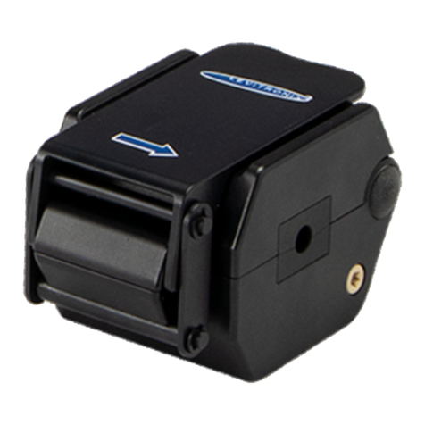
Levitronix LEVIFLOW LFSC-D Series User manual

User Manual for LEVIFLOW®LFSC-D Flowmeters
www.levitronix.com
PL-4507-00, Rev08, DCO# 20-024
First Release: 18-Dec-14
Last Update: 29-Jan-20
LEVIFLOW®CLAMP-ON
FLOWMETERS FOR FLEXIBLE TUBING
USER MANUAL
LEVIFLOW®Sensors: LFSC-05D (1 l/min), LFSC-08D (4 l/min)
LFSC-12D (20 l/min), LFSC-22D (80 l/min),
LFSC-30D (160 l/min)
LEVIFLOW®Converter: Single-Channel LFC-1C-PC
Multi-Channel LFC-6CIO-PC
This manual contains information necessary for the safe and proper use of the LEVIFLOW®clamp-on flowmeter
series. Included are specifications for the standard configuration, components, and instructions regarding its use,
installation, operation, adjustment, inspection and maintenance. For special configuration of the LEVIFLOW®
flowmeters refer to accompanying information. If the flowmeters must be configured for other parameter settings, then
the Levitronix®Service Software (with according manual Levitronix
Doc.# PL-4048-00) is necessary. For the multi-
channel converter LFC-6CIO-PC the Levitronix®Service Software version V2.0.5.0 or higher is needed. Please
familiarize yourself with the contents of this manual to ensure the safe and effective use of this product. After reading,
please store the manual where the personnel responsible for operating can readily refer to it at any time.

User Manual for LEVIFLOW®LFSC-D Flowmeters
www.levitronix.com
PL-4507-00, Rev08, DCO# 20-024
2
Table of Contents
1SAFETY PRECAUTIONS ..........................................................................................................................................3
2SPECIFICATIONS .....................................................................................................................................................4
2.1 Component Overview........................................................................................................................................4
2.2 Standard System Configuration.........................................................................................................................6
2.2.1 Multi-Channel Converter LFC-6CIO-PC............................................................................................................................6
2.3 Specifications of Flow Sensors..........................................................................................................................7
2.4 Specifications of Converters..............................................................................................................................7
2.5 Overview of Parameter Configuration................................................................................................................8
2.6 Basic Dimensions of Main Components............................................................................................................9
2.6.1 Dimensions of Clamp-On Sensors....................................................................................................................................9
2.6.2 Dimensions of Converter..................................................................................................................................................9
2.6.3 Dimensions of Adaptor Cables.......................................................................................................................................10
3INSTALLATION.......................................................................................................................................................12
3.1 Installation of Converter LFC-1C-PC...............................................................................................................12
3.1.1 Overview and Preparation..............................................................................................................................................12
3.1.2 Instructions for Electrical Installation...............................................................................................................................13
3.1.3 Instructions for Mechanical Installation...........................................................................................................................14
3.2 Installation of Converter LFC-6CIO-PC ...........................................................................................................15
3.2.1 Overview and Preparation..............................................................................................................................................15
3.2.2 Instructions for Electrical Installation...............................................................................................................................17
3.2.3 Instructions for Mechanical Installation...........................................................................................................................18
3.3 Installation of Sensors .....................................................................................................................................19
3.3.1 Overview and Preparation..............................................................................................................................................19
3.3.2 Instructions for Electrical Installation...............................................................................................................................19
3.3.3 Mechanical and Hydraulic Installation.............................................................................................................................20
3.3.4 Instructions for Tube Mounting.......................................................................................................................................21
4OPERATION............................................................................................................................................................23
4.1 General Timing Specifications.........................................................................................................................23
4.1.1 Startup Time ..................................................................................................................................................................23
4.1.2 Thermal Stability Time....................................................................................................................................................23
4.1.3 Zero Adjustment.............................................................................................................................................................23
4.2 System Operation with LFC-1C-PC.................................................................................................................23
4.2.1 Standalone Operation with Display.................................................................................................................................23
4.2.2 Operation with PLC Interface..........................................................................................................................................24
4.2.3 Operation with Levitronix®Service Software...................................................................................................................25
4.3 Operation with RS485......................................................................................................................................25
4.4 System Operation with LFC-6CIO-PC.............................................................................................................26
4.4.1 Standard Operation with PLC Interface ..........................................................................................................................26
4.4.2 Operation with RS485....................................................................................................................................................26
4.4.3 Standalone Operation with Display.................................................................................................................................26
4.4.4 Operation with Levitronix®Service Software...................................................................................................................26
5INSPECTION AND MAINTENANCE .......................................................................................................................27
6TROUBLESHOOTING.............................................................................................................................................27
6.1 Common Troubles...........................................................................................................................................27
6.2 Troubleshooting with Levitronix®Service Software..........................................................................................27
7TECHNICAL SUPPORT ..........................................................................................................................................28
8APPENDIX...............................................................................................................................................................29
8.1 Regulatory Status............................................................................................................................................29
8.1.1 CE Marking....................................................................................................................................................................29
8.1.2 Disposal of Equipment –WEEE Directive 2012/19/EU...................................................................................................29
8.2 Symbols and Signal Words..............................................................................................................................30

User Manual for LEVIFLOW®LFSC-D Flowmeters
www.levitronix.com
PL-4507-00, Rev08, DCO# 20-024
3
1 Safety Precautions
CAUTION
Do not under any circumstances open the converter or sensor housing.
Levitronix does not assume responsibility for any damage, which
occurs under such circumstances.
!
WARNING
Hazardous voltage may be present.
In case of the usage of an inadequate AC/DC power supply, mains
voltages may be present (even if the system is designed for 24VDC).
The converter must be placed in a spill protected environment. Do not
under any circumstances open the powered converter.
The usage of galvanic separated AC/DC supply is highly recom-
mended (preferable with UL 1950, UL 508C and/or IEC/EN60950).
!
WARNING
TOXIC CHEMICALS may be present.
When using the flowmeter to measure chemicals skin contact and toxic
gases may be hazardous to your health. Wear safety gloves and other
appropriate safety equipment.

User Manual for LEVIFLOW®LFSC-D Flowmeters
www.levitronix.com
PL-4507-00, Rev08, DCO# 20-024
4
2 Specifications
2.1 Component Overview
Figure 1: LEVIFLOW®flowmeter components
Figure 2: Accessories
Figure 3: Converter starter kit (see Table 2 Position 3) with components
Single-Channel Converter LFC-1C-PC
4-Digit Display
Zero Adjustment
Adress Setting for RS485
Piezo Transducers
In-/Output Electrical Interface
Digital
Signal Processor
DSP
LEVIFLOW®
Configuration Software
Interconnect Cable.
Flow Out
LEVIFLOW®
Life Science
Flow Sensor
Clamp-On
and
Single-Use
Series
Flow In
EMI Ferrite
LEVIFLOW®
Starter-Kit USB Stick
USB to RS485
Converter with Cable
Desktop AC/DC
Power Supply
AC Input AC Cable
Converter
Connection Cable
AC Mains Adaptor Set
(for various countries)
2
3
7
A
B
1c
1d
1b
6b
6a
A
5a
1e
5b
8
A
B
C
D
1a

User Manual for LEVIFLOW®LFSC-D Flowmeters
www.levitronix.com
PL-4507-00, Rev08, DCO# 20-024
5
Pos.
Part Name
Article #
Tube: ID x OD
Flow Range
Connector
Calibration Set
Note
1a
LFSC-05D-001
100-30407
ID = 1/8”= 3.2 mm
OD = 1/4”= 6.4 mm
1 lpm
Circular
Hirose
Water @ 20°C and
37°C
Silicone and C-Flex®
Default activated calibration
set is Silicone at 37°C
water temperature.
Other parameter sets can
be chosen with Levitronix®
Service Software.
1b
LFSC-08D-001
100-30396
ID = 1/4”= 6.4 mm
OD = 3/8”= 9.6 mm
4 lpm
1c
LFSC-12D-007
100-30390
ID = 3/8”=9.5 mm
OD = 9/16”=14.7 mm
20 lpm
1d
LFSC-22D-005
100-30391
ID = 3/4”=19.05 mm
OD = 1”=25.4 mm
80 lpm
1e
LFSC-30D-001
100-30414
ID = 1”=25.4 mm
OD = 13/8”=34.9 mm
160 lpm
Table 1: Standard flow sensor configurations
1: C-Flex®is a registered trademark of Saint Gobain Performance Plastics, 2015. All rights reserved.
Pos.
Part Name
Article #
Description
Interfaces
2
(A+6)
LFC-1C-PC
100-30374
Single Channel Converter
Analog Output (4 –20 mA), 2x Digital Output, 1x Digital Input,
RS485 (MODBUS) protocol
Note: EMI ferrite (7) for flow sensor cable and signal connector (A) included in
converter package.
3
(A+B)
LFC-6CIO-PC
100-30446
6-Channel Converter
with I/O Interfaces
(Digital I/O connector A and analog
output connector B included)
RS485 (MODBUS) protocol
6 analog outputs (4 –20 mA), 6 digital inputs, 6 digital outputs
Order Bus Conn. (6a) and Termination Box (6b) as separate article
Note 1: EMI ferrite (7) for supply/bus connection to be ordered as separate article.
When stacking multiple converters the EMI ferrite is needed on every sensor cable.
Note 2: Firmware version 08 or higher is necessary for the LFSC-D sensors.
4
(A-H)
LFC-1C-PC-SK
100-91072
Converter Starter Kit
Flow converter LFC-1C-PC (A) with Ferrite (B), AC/DC desktop supply
(C) with international AC mains inserts, sensor cable LFI-C.1-30 (D),
converter connection cable LFI-D.1 (E), RS485/USB cable YN-485I-TR
(F), USB stick with Levitronix Service Softw. and product Literature (G).
Table 2: LEVIFLOW®converters for clamp-on sensor
Pos.
Part Name
Article #
Features
Special Feature / Description
5a
LFI-C.1-10
LFI-C.1-30
LFI-C.1-60
190-10307
190-10308
190-10309
Cable length: 1 m, PVC
Cable length: 3 m, PVC
Cable length: 6 m, PVC
Interconnect cable for connection between sensor and converter.
5b
LFE-C.2-10
LFE-C.2-30
LFE-C.2-60
190-10310
190-10311
190-10312
Cable length: 1 m, PVC
Cable length: 3 m, PVC
Cable length: 6 m, PVC
Extension cable with wall-mountable connector for cabinet mounting.
Delivered with protective dust cap on wall-mountable connector side.
6a
Connector Box
for LFC-6CIO-PC
100-30447
COMBICON connector
For wiring RS485 and supply of stacks of LFC-6CIO-PC converter.
6b
Termination Box
for LFC-6C
100-30317
--
For termination of RS485 bus of LFC-6CIO-PC.
7
LeviFlow Splitting
Ferrite
100-30353
EMI filtering of DC supply
For LFC-6CIO-PC supply needed.
Needed on flow sensor cables, when stacking multiple converters.
8
YN-485I-TR, USB
to RS485 Adaptor-
TR Isolated
100-30392
Structure/Design
USB connector (A) with termination resistor and cable with connector
pair (B and C) for external RS485 wire connection. Magnetically
isolated. Cable length is 2m. Included is a USB space saver cable (D).
Purpose
Communication over fieldbus of converter with PC.
Table 3: Accessories
Pos.
Part Name
Part #
Flow Range
Calibration Set
Note
9a
LFSC-05D-001 + LFC-1C-PC
100-91113
0 –1 lpm
Water @ 20°C and 37°C
Silicone and C-Flex®
Extension and interconnect cables to be
ordered as separate article with specified
length (see Table 3).
Default activated calibration set is Silicone
at 37°C water temperature.
9b
LFSC-08D-001 + LFC-1C-PC
100-91076
0 –4 lpm
9c
LFSC-12D-007 + LFC-1C-PC
100-91012
0 –20 lpm
9d
LFSC-22D-005 + LFC-1C-PC
100-91013
0 –80 lpm
9e
LFSC-30D-001 + LFC-1C-PC
100-91183
0 –160 lpm
Table 4: Standard flowmeter sets –flow sensor with converter

User Manual for LEVIFLOW®LFSC-D Flowmeters
www.levitronix.com
PL-4507-00, Rev08, DCO# 20-024
6
2.2 Standard System Configuration
Figure 4: Clamp-on flowmeter configuration with LFC-1C-PC converter
(See Section 2.1 for positions/component descriptions)
2.2.1 Multi-Channel Converter LFC-6CIO-PC
Figure 5: Clamp-on flowmeter configuration with LFC-6CIO-PC converter
Single-Channel Converter LFC-1C-PC
4-Digit Display
Zero Adjustment
Adress Setting for RS485
Piezo Transducers
In-/Output Electrical Interface
Power Supply: 24 VDC
Analog and
Digital Outputs
- 1x Analog Output
- 2x Digital Outputs
- 1x Digital Input
Digital
Signal Processor
DSP
Flow In
Flow Out
Adaptor/Extension Cable
Wallmountable connector
for cabinet mounting
LEVIFLOW®
Clamp-On
Flowsensor
LFSC-xxD
Interconnect Cable
Various lengths.
Direct connection possible.
RS485 (MODBUS)
- Configuration with PC Software
- Data Logging
- Fieldbus Array of Multiple Sensors
EMI Ferrite
LEVIFLOW® Converter LFC-6CIO-PC
(6-Channel with I/O Signals)
4-Digit Display
Zero Adjustment
Address Setting for RS485
Piezo Transducers In-/Output
Signal/Power Bus Connector
Power Supply: 24 VDC
RS485 (MODBUS)
- Configuration with PC Software
- Data Reading
Digital
Signal Processor
DSP
Analog Output
Connector
Digital I/O
Connector
Analog Outputs:
6 Channels
Digital Outputs:
6 Channels
Digital Inputs:
6 Channels
EMI
Ferrite
LEVIFLOW®
Clamp-On
Flowsensor
LFSC-xxD
Adaptor/Extension Cable
Wallmountable connector
for cabinet mounting
Interconnect Cable
Various lengths.
Direct connection possible.
LEVIFLOW®
Clamp-On
Flowsensor
LFSC-xxD
1
5a
5b
2
7
1
5a
5b
3
7

User Manual for LEVIFLOW®LFSC-D Flowmeters
www.levitronix.com
PL-4507-00, Rev08, DCO# 20-024
7
2.3 Specifications of Flow Sensors
Characteristics
LFSC-05D
LFSC-08D
LFSC-12D
LFSC-22D
LFSC-30D
Flow Range [l/min]
0 –1 l/min
0 –4 l/min
0 –20 l/min
0 –80 l/min
0 –160 l/min
Accuracy of Reading
(Tubing variation not included.)
±5 % for > 25% of FS
±12.5 ml/min for < 25% of FS
±3 % for > 15% of FS
±18 ml/min for < 15% of FS
±3 % for > 15% of FS
±90 ml/min for < 15% of FS
±3 % for > 15% of FS
±360 ml/min for < 15% of FS
±3 % for > 15% of FS
±720 ml/min for < 15% of FS
Weight
212 g
211 g
208 g
327 g
502 g
Maximum Fluid Pressure
(max. pressure of tube might limit this value)
6.5 bar
6.5 bar
6.5 bar
4 bar
3 bar
Pressure Drop Coefficient C 2
P = C x Q2 , (for water), Q = Flow [l/min]
P = Press. Drop [kPa = 10 mbar]
4.16 at 20°C
3.77 at 37°C
0.0743 at 20°C
0.0675 at 37°C
0.00725 at 20°C
0.00658 at 37°C
1.49 10-4 at 20°C
1.34 10-4 at 37°C
3.9 10-5 at 20°C
3.5 10-5 at 37°C
Usable
Flexible Tubing
Dimensions
ID
1/8” = 3.2 mm
1/4” = 6.4 mm
3/8” = 9.5mm
3/4” = 19.05 mm
1” = 25.4 mm
OD
1/4” = 6.4 mm
3/8” = 9.6 mm
9/16” = 14.3mm
1” = 25.4 mm
13/8” = 34.9 mm
Wall thickness
1/16” = 1.6 mm
1/16” = 1.6 mm
3/32” = 2.4 mm
1/8” = 3.2 mm
3/16” = 4.8 mm
Standard Tube Material
Saint Gobain C-Flex®1(374, 072 and 082) and Silicone (Pharma 50, 65 and 80)
Fluid / Ambient Temperature
Normal range: 10 –60 °C ( 50 –140 °F ) / 0 –40 °C (32 - 104 °F)
Measurable Viscosity / Sound Speed
0.7 –10 mm2/s (0.7 –10 cSt) / 1300 –1700 m/s (others on request)
IP Classification / Allowed Cleaning
IP-65 / Wiping with IPA or water
Electrical Connector / Cables
Circular type (IP-67), lock-release mounting / Various extension cables available.
Table 5: Specifications of clamp-on sensors LFSC-xxD
1: C-Flex®is a registered trademark of Saint Gobain Performance Plastics, 2015. All rights reserved.Note 2: Calculated values.
2.4 Specifications of Converters
Characteristics
Description or Values
Power Supply Voltage / Current / Inrush Current
24 VDC ± 10% / 150 mA / 3.8 A peak during < 210 µs
Ambient Temp / Humidity Range
0 –50 °C (32 –122 °F) / 30 - 85% R.H. (no condensation)
Enclosure Classification and Material
IP-20 (indoor use), ABS
Interfaces
(see Figure 7 for detailed PIN designation and electrical
specification)
- RS485 -> MODBUS protocol -> max. array of 99 channels
- 1x Analog Output: 4 –20mA (0 –20mA configurable)
- 2x Digital Outputs: Flow Alarm, Measurement Error, Volume Counter Pulse, Volume Counter Alarm, Flow as
Frequency or Bubble Detection, Custom Output (default: normally open)
- 1x Digital Input: Volume Counter Reset or Zero Adjust
- 4 Digit display (flow rate, volume counter, error codes), re-zero button
- Address potentiometers for RS485 address setting
Configuration Parameters
(Available and configurable with RS485/USB converter and
service software)
- Viscosity
- Low Cutoff
- Dampening time (filter)
- Full scale setting
- Linearization (15 points)
- Alarm Outputs (High and Low Alarm)
- Volume Counter and Volume Counter Alarm Settings
Weight / Dimensions / Mounting
130 g / 123 x 75 x 17.5 mm / DIN rail
Duration for Digital and Manual Zeroing
Duration of Measurement Ready after Power-On
Duration for activation: 3 sec Duration of zeroing procedure: normal 26 sec , max. 60 sec
Measurement ready after power-on: 10 sec. Warm-up for full performance: 30 min.
Table 6: Specifications for converter LFC-1C-PC
Characteristics
6-Channel Converter LFC-6CIO-PC
Power Supply Voltage / Current / Inrush Current
Ambient Temp / Humidity Range
24 VDC ± 10% / 270 mA / Inrush Peak 4.9 A within 180 µs
0 –50 °C (32 –122 °F) / 30 - 85% R.H. (no condensation)
Enclosure Classification and Material
IP-20 (indoor use), ABS
Interfaces
(see Table 10 for LFC-6C and Table 10/Table 11/Table 12 for
LFC-6CIO for detailed PIN designation and electrical
specification)
- RS485 -> MODBUS protocol -> max. array of 99 ch.
- 4 Digit display (flow rate, volume counter, error codes), re-zero button
- Address potentiometers for RS485 address setting
- 6x Analog Outputs: 4 –20mA (0 –20mA configurable)
- 6x Digital Outputs: Flow Alarm, Measurement Error, Volume Counter Pulse, Volume Counter Alarm, Flow as
Frequency or Bubble Detection, Custom Output (default: normally open)
- 6x Digital Input: Volume Counter Reset or Zero Adjust
Configuration Parameters
(Available and configurable with RS485/USB converter and
service software)
- Viscosity
- Low Cutoff
- Dampening constant (filter)
- Full scale setting
- Linearization (15 points)
- Alarm Outputs (High and Low Alarm)
- Volume Counter and Volume Counter Alarm Settings
Weight / Dimensions / Mounting
215 g / 140 x 77.3 x 20.5 mm / DIN rail
Duration for Digital and Manual Zeroing
Duration of Measurement Ready after Power-On
Duration of activation: 3 sec Duration of procedure: normal 26 sec, maximum 60 sec.
Measurement ready after power-on: 10 sec. Warm-up for full performance: 30 min.
Table 7: Specifications for multi-channel converter LFC-6CIO-PC
Note: Due to the reduced flow sampling rate per channel, the multi-channel converter LFC-6CIO-PC may not be suitable
for highly dynamic flow measurements in the lower flow range (like for example for flows with sharp pulses caused by
roller pumps).

User Manual for LEVIFLOW®LFSC-D Flowmeters
www.levitronix.com
PL-4507-00, Rev08, DCO# 20-024
8
2.5 Overview of Parameter Configuration
Table 8 shows the standard (“Default”) and possible parameter configurations of the clamp-on flowmeters.
This user manual is dealing with the standard configuration. For setting up other configurations the
Levitronix®Service Software is needed. Consult the relevant manual (see reference on title page of this
manual) for more detailed description.
Block
Parameter
Option/Range
Default for
LFSC-Series
Sensors
Note
Basic
Sensor size
LFSC-xxD
xx = 05, 08, 12, 22 or 30
Automatically set.
--
Full scale
0.01 –100 L/min
Automatically set.
Default is LFSC-08D=4 l/min, LFSC-12D=20 l/min,
LFSC-22D=80 l/min LFSC-30D=160 l/min
Damping time
0 –25 s
2.0 s
Low-pass filter with
T
fdB
=
21
3
Low cutoff
0.0 –25.0 %
2 %
Flow cut to 0 below this percentage of full-scale
If cutoff 0% is chosen, negative flow becomes visible
Kinematic Viscosity
0.00 –99.99 cSt
Automatically set.
Kinematic Visc. = Dynamic Visc. / Density
Not implemented for LFSC-D series sensors.
Display
Settings
Displayed Parameter
Flow Value in L/min
Flow Value in mL/min
Volume Counter Value
Flow Value in L/min
Parameter shown on converter display.
Measurement Resolution
0 digits (#.)
1 digits (#.#)
2 digits (#.##)
3 digits (#.###)
3 digits (#.###)
Configures number of digits after decimal point
displayed.
Analog output
settings
Analog output setting
4 –20 mA or
0 –20 mA
4 –20 mA
--
Digital input
settings
Digital input
Volume counter reset
Zero adjust
Set Volume Counter to zero
Zero adjust
Automates zeroing, when liquid type changes
Digital output
settings
Digital output 1
Flow alarm High
Flow alarm Low
Vol. counter alarm H
Vol. counter alarm HH
Vol. counter Pulse
Measurement Error
Flow as Frequency
Bubble detect
Custom Output
Flow alarm High
- Upper flow limit detection
- Lower flow limit detection
- Flow volume detection first value (one-time)
- Flow volume detection second value
- Pulse per volume
- Error signal (empty sensor etc.)
- Flow as Frequency output (100% of full-scale = 1 kHz)
- Bubble detected signal
- Bits of equipment status can be OR-ed on the output
Digital output 2
Flow alarm Low
Flow alarm
Hysteresis (Flow alarm)
0 –20 %
0 %
Can be used to get tolerance to noise.
Alarm high
0 –125 %
105 %
Alarm setting In percentage of full-scale.
Contact type
N.O. = normally open
N.C. = normally closed
N.O. = norm. open
-
Alarm low
-10 –125 %
- 5 %
Alarm setting In percentage of full-scale.
Contact type
N.O. = normally open
N.C. = normally closed
N.O. = norm. open
-
Volume counter
settings
Volume counter enable
(activation box)
activated, not activated
not activated
These are settings for volume detection (integration of
flow).
Has to be active for the options “ Vol. Counter Alarm H”,
“Vol. Counter Alarm HH” and “Vol. Counter Pulse”.
Volume counter base unit
1 mL, 1 L, 1 m3
1 mL
Multiplier factor
0.01, 0.1, 10, 100, 1000
0.1
Volume counter pulse length
0.5, 50, 100ms
0.5 ms
Volume counter alarm enable
(activation box)
activated, not activated
not active
-> Settings for one-time volume detection.
-> Volume = “Volume unit” x “Multiplier factor” x “Vol.
Counter Alarm H“ value”
-> Has to be active for the options “Vol. Counter Alarm
H”, “Vol. Counter Alarm HH”.
Value (Volume counter alarm H)
0 –999999
--
Contact type (H)
N.O. = normally open
N.C. = normally closed
N.O. = norm. open
Value (Volume counter alarm HH)
0 –999999
--
Contact type (HH)
N.O. = normally open
N.C. = normally closed
N.O. = norm. open
Measurement
Error Settings
Instant Measurement Error Ignore
Time
0-99 s
10s
During this time instant measurement errors are ignored.
If an instant measurement error stays active for longer
time than this time, measurement error arises.
Flow Level on Measurement Error
0%, -25, 125%
Hold
0 %
Signal level of analog output and flow, when
measurement error arises
Bubble
Detection
Settings
Bubble Detect Hold Time
0 –99 s
0 s
For bubble or particle detection in the process
Table 8: Overview of parameters

User Manual for LEVIFLOW®LFSC-D Flowmeters
www.levitronix.com
PL-4507-00, Rev08, DCO# 20-024
9
2.6 Basic Dimensions of Main Components
2.6.1 Dimensions of Clamp-On Sensors
Sensor Type
Clamp
Type
Dimensions in [mm]
A
B
C
D
E
F
G
H
LFSC-05D
2
5.7
48
54
67.2
44.5
M6 x 6
20
35
LFSC-08D
2
8
48
54
67.2
44.5
M6 x 6
20
35
LFSC-12D
1
12
48
54
67.2
44.5
M6 x 6
20
35
LFSC-22D
2
22
54
65
80.7
57.5
M8 x 10
25
56
LFSC-30D
2
29.5
54
85.5
102.1
79.8
M8 x 10
25
30
Figure 6: Dimensions of LFSC-xxD clamp-on sensors
2.6.2 Dimensions of Converter
Figure 7: Dimensions and layout of interfaces of converter LFC-1C-PC
Type 1
Type 2
LFC-1C-PC
100-30374

User Manual for LEVIFLOW®LFSC-D Flowmeters
www.levitronix.com
PL-4507-00, Rev08, DCO# 20-024
10
Figure 8: Dimensions and stacking concept of multi-channel converter LFC-6CIO-PC
2.6.3 Dimensions of Adaptor Cables
Figure 9: Dimensions of interconnect cable LFI-C.1
(Minimum bending radius > 10 x cable radius)
Length = 3m
Connector Box
(RS485 and Supply Bus)
EMI Ferrite
Termination
Box)
Connector
Hirose Plug Female
HR30-6P-6S
Connector
Hirose Plug Male
HR30-6P-6P

User Manual for LEVIFLOW®LFSC-D Flowmeters
www.levitronix.com
PL-4507-00, Rev08, DCO# 20-024
11
Figure 10: Dimensions of wall mountable extension cable LFE-C.2
(Can be used for electrical cabinet mounting. Minimum bending radius > 10 x cable radius.)
Mounting Panel Dimensions
Length = 1m

User Manual for LEVIFLOW®LFSC-D Flowmeters
www.levitronix.com
PL-4507-00, Rev08, DCO# 20-024
12
3 Installation
3.1 Installation of Converter LFC-1C-PC
3.1.1 Overview and Preparation
Figure 11: Single channel converter LFC-1C-PC
PIN
Designation
Specification
Standard Configuration
Description
1
DC24V+
Voltage: 24 VDC ±10%
Current: 150 mA
Inrush current: 4.4 A 2ms
--
Supply voltage
2
DC24V-
3
FG
Field Ground
See note in installation Section 3.1.2
Field ground
4
Analog Out +
4-20 mA or 0-20mA configurable
Load resistance < 600
Flow reading with 4-20 mA
Standard full scale flow range of each
sensor model.
Flow rate signal.
Update rate is 10ms.
5
Analog Out -
6
Digital Out1 +
Max. rating 30 V DC, 20 mA
Open collector
Configurable as Alarm High, Alarm Low,
Measurement Error, Volume Counter
Pulse, Volume Counter Alarm, Flow as
Frequency, Bubble Detect
- Parameter: Flow Alarm Low
- Setting: 12% of full scale
- Non contact type
Contact is made, when flow is below of 12% of
full scale.
7
Digital Out2 -
- Parameter: Measurement Error
- Non contact type
Contact is made, when measurement error is
occurred.
8
COM
--
Common Digital Out ground.
9
Digital In +
No-voltage contact or transistor oper.
Zero Adjustment
Is needed, if zero adjustment wants to be
triggered by PLC or when volume counter
function is used (integration of flow with volume
detection)
10
Digital In -
11
RS485 +
RS485
MODBUS Protocol
Digital communication in a sensor array.
or configuration with service SW.
12
RS485 -
Table 9: Standard configuration of electrical interface (PLC and fieldbus)
Note 1: Min torque for connector screws is 0.5 Nm and max. is 0.6 Nm.
a
DIN Rail Mounting
Sensor Connectors
Interface Connector (12 Pin)
b
Re-Zero Button
High ADRS
LOW ADRS
4 Digit Display
c
LFC-1C-PC

User Manual for LEVIFLOW®LFSC-D Flowmeters
www.levitronix.com
PL-4507-00, Rev08, DCO# 20-024
13
1. If communication over the RS485 bus is used, check the address settings of the potentiometers on
the front panel of the converter (see Figure 11c). The total address is: “High ADRS” x 10 + “Low
ADRS” x 1.
2. The Levitronix®Service Software can be used to debug and configure the flowmeter over the RS485.
For communication with RS485 the MODBUS protocol can be requested at Levitronix
.
3.1.2 Instructions for Electrical Installation
1. Remove the DC power from the converter.
2. Remove the interface connector (see Figure 11a) from the converter.
3. Attach the necessary wires (AWG 14-26) according to the pin specifications in Table 9. Strip the
sheath approximately 3 mm from the wires end. Insert core into terminal to the end and tighten the
screw. Confirm that the wires are securely fixed by pulling it gently by hand.
4. Note: The Field Ground (FG) represents an additional ground potential, which is connected internally
to the signal ports of the converter via varistors. Depending on the specific setup, it might be
advantageous from an EMC perspective to connect the FG to the PE. However, in case the FG is
connected to PE the entire grounding concept of the field installation must be considered in order to
avoid stray and compensating currents triggered by electrical potential differences. If compensating
currents between PE and Ground may occur, the FG should not be connected.
5. For usage of a fuse at the power input (24 VDC) a 200 mA slow-blow type is recommended. The
peak current (inrush current) after power on of the converter (as specified in Table 9) has to be
considered, when choosing the fuse type and the AC/DC power supply.
6. Mount the interface connector to the converter and tighten the 2 connector screws.
7. To attach the sensor to the converter extension cables according to Table 3 can be used. To
increase robustness against disturbance from other devices or to reduce cross-talking between
multiple flowmeters, the converter comes delivered with an EMI ferrite, which shall be attached to the
sensor cable near to the converter (see Figure 12):
Figure 12: Assembly of EMI ferrite
8. Before powering on check again all wiring connections. Confirm that the terminals are securely
fastened and that there is no possibility of short circuit.

User Manual for LEVIFLOW®LFSC-D Flowmeters
www.levitronix.com
PL-4507-00, Rev08, DCO# 20-024
14
3.1.3 Instructions for Mechanical Installation
!
WARNING
Hazardous voltage may be present.
In order to avoiding fluid spills shorting voltages within the converter,
place the controller in a spill protected environment (for example
protected electronic cabinets).
If explosive flammable gases are present, place the converter in an
explosion-proof cabinet.
1. The converter shall be installed in a spill protected cabinet.
2. Assure that enough ventilation is provided in order to avoid exceeding the allowed ambient temperature and
humidity range: Temperature range: 0–40°C (32–104°F), Humidity range: 30-85% R.H. (no condensation).
3. A wall-mountable extension cable (see Table 3 and Figure 10) is provided in order to panel mount the sensor
cable on the cabinet wall. Make a whole to the cabinet wall according to Figure 10. The gasket ring delivered
with the extension cable can be used on the inside of the cabinet wall hence achieving an IP-67 sealing.
4. For connecting the sensor to the wall-mountable connector on the cabinet the interconnect cable according to
Table 3 and Figure 7 can be used.
Step 1: Align first the Snap-Pin side of the converter
with the DIN rail corner (picture a). If the rigid
side is aligned first (see picture b) than some of
the DIN rail parts of the converter housing might
be damaged.
Step 2: Press in the converter on the spring-pin side
(see picture c).
Step 3: Press in the fix side of the DIN rail recess of the
converter housing (see picture d)
Step 4: Relax the converter and let the snap-pin fix it
(see picture e).
Figure 13: Din Rail mounting steps for converter LFC-1C-PC
(For dismounting follow the steps in reverse order.)
a
b
c
d
e
Snap Pin

User Manual for LEVIFLOW®LFSC-D Flowmeters
www.levitronix.com
PL-4507-00, Rev08, DCO# 20-024
15
3.2 Installation of Converter LFC-6CIO-PC
3.2.1 Overview and Preparation
Figure 14: Multi-channel controller LFC-6CIO-PC
Fixation Bars
(un-locked)
Fixation Bars
(un-locked,
on both sides)
Connector Box
Termination
Box
EMI Ferrite
Zeroing
Botton
Channel Select 1-6
Address Setting for RS485:
High Adrs Low Address
4 Digit LED Display
Channel Indication 1-6
Bus Connector:
Pin #1
Pin #7
Sensor
Connectors:
Channel #6
Channel #1
Connector
Analog Output
Connector
Digital I/O
Connector
Analog Output
Connector
Digital I/O
Fixation Bars
(locked)
Fixation Bars
(locked on both sides)

User Manual for LEVIFLOW®LFSC-D Flowmeters
www.levitronix.com
PL-4507-00, Rev08, DCO# 20-024
16
Pin #
Designation
Specification
1
NC
Not connected.
2
+24 V
24 VDC ± 10% / 270 mA / Inrush Peak 4.9 A within 180 µs
Note: Usage of twisted pairs in a shielded cable recommended.
3
0 V
4
FG
Field Ground. See note in installation Section 3.2.2
5
TRX+
RS485 with MODBUS protocol
Digital communication in a sensor array or configuration with service SW.
Note: Usage of twisted pair wires in a shielded cable recommended.
6
TRX-
7
TRXG
RS485 ground. If possible, to be connected to the ground of the RS485 master.
Note 1: Can be led in the same cable as TRX+/TRX-.
Table 10: Standard configuration of bus connector of LFC-6CIO-PC
Pin
Designation
Pin #
Designation
Specification
Standard Configuration
1
Analog Out CH1+
7
Analog Out CH4+
4 - 20 mA
(0 –20 mA configurable)
Load resistance < 600 Ohm
Flow reading with 4-20 mA. Standard full scale
flow range of each sensor model.
Flow rate signal.
Update rate is 5 ms per channel.
2
Analog Out CH1-
8
Analog Out CH4-
3
Analog Out CH2+
9
Analog Out CH5+
4
Analog Out CH2-
10
Analog Out CH5-
5
Analog Out CH3+
11
Analog Out CH6+
6
Analog Out CH3-
12
Analog Out CH6-
Table 11: Standard configuration of analog output connector for LFC-6CIO-PC
Note 1: Min torque for connector screws is 0.5 Nm and max. is 0.6 Nm.
Digital Outputs
Digital Inputs
Pin
Designation
Specification
Standard Configuration
Pin
Designation
Specification
Standard Configuration
1
Digital Out CH1+
Maximum rating:
30 VDC, 20 mA
(open collector)
- Parameter: Flow Alarm High
- Setting: 105% of full scale
- Normally opened
Contact is made, when 105% of
full scale flow rate is exceeded.
13
Digital In CH1+
No-voltage
contact or
transistor open
collector.
Zero Adjustment
Is needed, if zero adjustment
wants to be triggered by PLC or
when volume counter function is
used (integration of flow with
volume detection)
2
Digital Out CH1-
14
Digital In CH1-
3
Digital Out CH2+
15
Digital In CH2+
4
Digital Out CH2-
16
Digital In CH2-
5
Digital Out CH3+
17
Digital In CH3+
6
Digital Out CH3-
18
Digital In CH3-
7
Digital Out CH4+
19
Digital In CH4+
8
Digital Out CH4-
20
Digital In CH4-
9
Digital Out CH5+
21
Digital In CH5+
10
Digital Out CH5-
22
Digital In CH5-
11
Digital Out CH6+
23
Digital In CH6+
12
Digital Out CH6-
24
Digital In CH6-
Table 12: Standard configuration of digital in/output connector for LFC-6CIO-PC
Note 1: Min torque for connector screws is 0.5 Nm and max. is 0.6 Nm.
1. Check if all parts are delivered as shown in Figure 14. For every configuration (single
converter as shown in Figure 14aand multi converter array as in Figure 14b) a termination
box (resistance to terminate the RS485) and a connector box (wiring) is needed.
2. For communication with RS485 check the address settings of the potentiometers on the front
panel of the converter (see Figure 14d). The total address of the first channel is:
“High ADRS” x 10 + “Low ADRS” x 1
3. The Levitronix®Service Software can be used to debug and configure the flowmeter over the
RS485. For communication with RS485 the MODBUS protocol can be requested at
Levitronix
.

User Manual for LEVIFLOW®LFSC-D Flowmeters
www.levitronix.com
PL-4507-00, Rev08, DCO# 20-024
17
3.2.2 Instructions for Electrical Installation
1. Remove the DC power supply from the converter.
2. Remove the interface connector on the connector box (see Figure 14).
3. Attach the necessary wires (AWG 14-26) according to the pin specifications in Table 10, Table 11 or Table 12.
Strip the sheath approximately 3mm from the wires end. Insert the core into the connector up to the end and
tighten the screw. Confirm that the wires are securely fixed by pulling it by hand.
4. Note: The Field Ground (FG) represents an additional ground potential, which is connected internally to the
signal ports of the converter via varistors. Depending on the specific setup, it might be advantageous from an
EMC perspective to connect the FG to the PE (protective earth). However, in case the FG is connected to PE
the entire grounding concept of the field installation shall be considered in order to avoid stray and
compensating currents triggered by electrical potential differences. If compensating currents between PE and
Ground may occur, the FG should not be connected.
5. For usage of a fuse at the power input slow-blow type with a current rating of the converters (see Table 7) and
25% additional margin is recommended. Consider the inrush current of the converters (see Table 7) during
power start-up, when choosing the fuse type and the AC/DC power supply.
6. Mount the bus connector to the converter and tighten the 2 connector screws.
7. Before powering on, check again all wiring connections. Confirm that the terminals are securely fastened and
that there is no possibility of short circuit.
8. For proper EMI behavior of the LFC-6CIO-PC a ferrite is needed. This can be ordered according to Table 3
and assembled according to Figure 15. All bus wires shall be covered and the ferrite shall be placed at a
distance not longer than 15 cm from the connector box of the converter (see also Figure 8).
Figure 15: Mounting of EMI ferrite for bus wires of LFC-6CIO-PC (See Table 3 for order information)
9. If multiple LFC-6CIO-PC are stacked as illustrated in Figure 14, every sensor cable shall be configured with a
ferrite according to Figure 16 (see Table 3 for order information) in order to avoid cross talking of the sensor
signals. The ferrites shall be placed as near as possible to the beginning of the sensor cable (near to the
plastic connector).
Figure 16: EMI ferrites for sensor cables, when stacking multiple LFC-6CIO-PC
LEVIFLOW® Converter LFC-6CIO-PC
(6-Channel with I/O Signals)
4-Digit Display
Zero Adjustment
Address Setting for RS485
Piezo Transducers In-/Output
Signal/Power Bus Connector
Power Supply: 24 VDC
RS485 (MODBUS)
- Configuration with PC Software
- Data Reading
Digital
Signal Processor
DSP
Analog Output
Connector
Digital I/O
Connector
Analog Outputs:
6 Channels
Digital Outputs:
6 Channels
Digital Inputs:
6 Channels
LEVIFLOW®
Clamp-On
Flowsensor
LFSC-xxD
Adaptor/Extension Cable
Wallmountable connector
for cabinet mounting
Interconnect Cable
Various lengths.
Direct connection possible.
LEVIFLOW®
Clamp-On
Flowsensor
LFSC-xxD
EMI
Ferrite
EMI Ferrite for Sensor Cables
For stacking of multiple
converters necessary.
EMI
Ferrite
EMI
Ferrite
EMI
Ferrite
EMI
Ferrite
7
7

User Manual for LEVIFLOW®LFSC-D Flowmeters
www.levitronix.com
PL-4507-00, Rev08, DCO# 20-024
18
3.2.3 Instructions for Mechanical Installation
!
WARNING
Hazardous voltage may be present.
In order to avoiding fluid spills shorting voltages within the converter,
place it in a spill protected environment (for example protected
electronic cabinets).
If explosive flammable gases are present, place the converter in an
explosion-proof cabinet.
1. The converter shall be installed in a spill protected cabinet.
2. Assure that sufficient ventilation is provided in order to avoid exceeding the allowed ambient
temperature and humidity range specified in Table 7:
3. Bring the fixation bars into un-lock position (see Figure 14).
4. If multiple converters are used (see Figure 14) stack them together.
5. Attach the connector box (see Figure 14)
6. Attach the termination box (Figure 14) and fix it by pushing the fixation bars of the termination
box (see Figure 14) to the inside.
7. Bring the fixation bars into the locked position (see Figure 14)
8. Mount the whole stack on a DIN rail following the same steps as described in Figure 13 for
the single channel converter LFC-1C-PC.

User Manual for LEVIFLOW®LFSC-D Flowmeters
www.levitronix.com
PL-4507-00, Rev08, DCO# 20-024
19
3.3 Installation of Sensors
3.3.1 Overview and Preparation
Figure 17: Clamp-on flow sensor model LFSC-xxD
1. Every sensor comes delivered with a calibration sheet. Check if the S/N on the calibration
sheet corresponds to the S/N on the type label of the sensor.
2. Please store the delivered calibration sheet or its data on a defined storage place in order to
be able to refer to it in case of problems.
3.3.2 Instructions for Electrical Installation
1. Attach one of the extension cables (see Table 3) coming from the converter to the sensor
connector.
2. When applying power, the controller needs about 10 seconds for a start-up procedure to be
ready. In order to get stable temperature and signals for converter and sensor 30 minutes
shall be waited after power-on.
3. After start-up a Zeroing is recommended. Assure that the sensor is filled completely with the
according fluid, free of bubbles and that zero flow is realized. Then push the “ZERO ADJ”
button on the converters for about 3 seconds. During adjustment “0ADJ” appears on the
converter display (about 2 seconds with blinking). The zero adjustment procedure will take
about 26-60 seconds.
Flexible Tube
Circular Connector
(Watertight)
Transducer Area
Flow Direction

User Manual for LEVIFLOW®LFSC-D Flowmeters
www.levitronix.com
PL-4507-00, Rev08, DCO# 20-024
20
3.3.3 Mechanical and Hydraulic Installation
1. In order to mechanically fix the sensor body, 2 fixation threads on the backside of the sensor
housing can be used (see Figure 6).
2. Assure that at the mounting location, the allowed ambient temperature range (Table 5) is not
exceeded.
3. Clamp the sensor to the tubing according to the procedure described in Section 3.3.4. Use only
tubing material for the specified calibration (see calibration sheet).
4. The flow circuit should be filled completely with fluid. The converter DSP (Digital Signal Processor)
contains special algorithms, which increase the robustness of the measurement against bubbles.
However, assure that excessive bubbles are avoided in the circuit.
5. Ideal mounting position for the flow sensor is a slight angle with upward flow direction to avoid the
stagnation of bubbles and particles in the measuring path of the tubing.
6. An arrow mark on the flow sensor (see Figure 17) indicates the flow direction. Make sure that the
arrow corresponds to the direction of the flow in the hydraulic circuit.
7. Avoid excessive vibrations such as in the vicinity of displacement pumps. Vibrations might
influence the flow measurement. If vibrations sources can not be avoided, acoustic decoupling
technics between flowmeter and vibration source shall be considered.
8. The flowmeter measures flow velocity. In order to obtain fully developed flow pattern for accurate
velocity measurement, straight run of 30x tubing ID upstream and of 12x tubing ID downstream is
recommended (see Table 5 for ID specifications of the sensor models). If non-uniform turbulent
flow or swirl flow is expected, install longer upstream straight run and/or a flow-rectifier.
9. To install on a tubing that has open end, the sensor should be mounted in lower position of the
pipeline.
10. The sensor should be mounted where pressure in the pipe is above the atmospheric pressure in
order to avoid bubble generation by cavitation effects.
11. Devices like valves are recommended to be installed downstream of the sensor in order to prevent
formation of bubbles in the liquid. An upstream valve may form bubbles reducing the intensity of
the ultrasound signal and interfering with measurement.
12. A bypass pipe run (including bypass valve and shutoff valve) may be used for easy zero
adjustment and maintenance.
13. Please confirm that the maximum pressure is below the maximum pressure of the flexible tubing
and the maximum pressure of the sensor specified in Table 5.
14. After setup a “Zeroing”is recommended. Assure that the sensor is filled completely with the
according fluid and is free of bubbles. Stable liquid properties should be assured by flushing the
circuit with the final liquid until temperature and viscosity becomes stable. After this, zero flow shall
be realized. Then push the “ZERO ADJ” button on the converters for about 3 seconds. During
adjustment “0ADJ” appears on the converter display (about 2s with blinking). The duration of
zeroing is about 26-60 seconds.
15. If Re-Zeroing is regularly necessary, automation is possible over the digital input of the converter.
For the configuration of the digital input the Levitronix®Service Software is needed. Consult the
manual of the service software for more detailed description.
16. In the following cases a re-zero is recommended:
a. 30 minutes after power-on of a cool converter and sensor
b. Change of fluid properties (temperature, viscosity, density)
c. Change of chemistry
d. Clamp-on of the sensor to a new tubing
e. Change of the hydraulic circuit
This manual suits for next models
5
Table of contents
Other Levitronix Measuring Instrument manuals