Lewmar 250 VRTT Series User manual

250 & 300 VRTT
Revision D07/03/07

1
INDEX
Page
1.INTRODUCTION 2
2.INSTALLATION
2.1 Fitting the Thruster
2.1.1 Placement 3
2.1.2 Lifting 4
2.1.3 Hull fitting 4
2.1.4 Raise/Lower setting 6
2.1.5 Painting 7
2.2 Thruster Main Drive Installation
2.2.1 Hydraulic 8
2.2.2 Electric 9
2.3 Thruster Electrical Control Installation 14
3.OPERATION 22
4. MAINTENANCE
4.1 Periodic Maintenance 24
4.2 Cathodic Protection 25
4.3 Manual Operation 26
5.DRAWINGS 27
WARRANTY

2
1. INTRODUCTION
The Lewmar VRTT Thruster has been designed to give excellent service and
a long life providing that it is installed and serviced properly.
This manual provides the information required for the correct installation of
your new Lewmar VRTT Thruster
This manual applies to the following thruster models:
59127002 – 250 VRTTH (low displacement)
59127004 – 250 VRTTH (high displacement)
59127100 – 250 VRTTE 24VDC
59127110 – 250 VRTTE 48VDC
59137001 – 300 VRTTH (low displacement, aluminium)
59137002 – 300 VRTTH (low displacement, bronze)
59137003 – 300 VRTTH (high displacement, aluminium)
59137004 – 300 VRTTH (high displacement, bronze)
If there is any problem found during installation or use, contact your nearest
Lewmar agent or contact us at www.lewmar.com
Note. Additional accessories such as control panels and looms may be
required for the control of your new thruster.
Please refer to section 2.3 (page 14.)
IMPORTANT:
- Please ensure that you thoroughly understand the operation and
safety requirements of the thruster
- Your thruster should not be operated close to swimmers as a
powerful suction of water is generated when in use.
- All hull modifications should be carried out by a specialist.
- We recommend that a qualified person install the thruster. Faulty
installation could place the boat and crew in danger and make the
warranty invalid.
- Do not use the thruster assembly as an earth point

3
2. INSTALLATION
These are guidelines only it is recommended that a professional marine
engineer perform the Thruster installation.
2.1 Fitting the Thruster
The VRTT Thruster is supplied with the leg raised for ease of installation.
Correct installation of the Thruster, associated equipment and the watertight
integrity of the vessel is the responsibility of the installer.
2.1.1 Placement
The Thruster should be installed as far forward as possible. When the VRTT
is lowered to the Thrust position, the centre line of the hub must be a
minimum of 1.5 x propeller diameter below the water line and clear of the hull.
The performance of the Thruster is largely due to the power source supplying
the Thruster motor.
Adequate space should be allowed inside the hull for hydraulic hoses, electric
cables and access for service etc. It is also important that the area around the
thruster be kept clear of any loose items. It is recommended that if the area is
to be used for additional storage that a removable cover or barrier be
constructed around the unit to prevent damage to the unit. This area must
also be kept dry to avoid damage to the electric motors and that they have
sufficient room to breath, ideally housed in a ventilated area. If a 250VRTTE is
fitted the electric thrust motors will get hot.
It is important that nothing can cause jamming of the raise/lower
mechanism or damage to the stop switches.

4
2.1.2 Lifting the unit
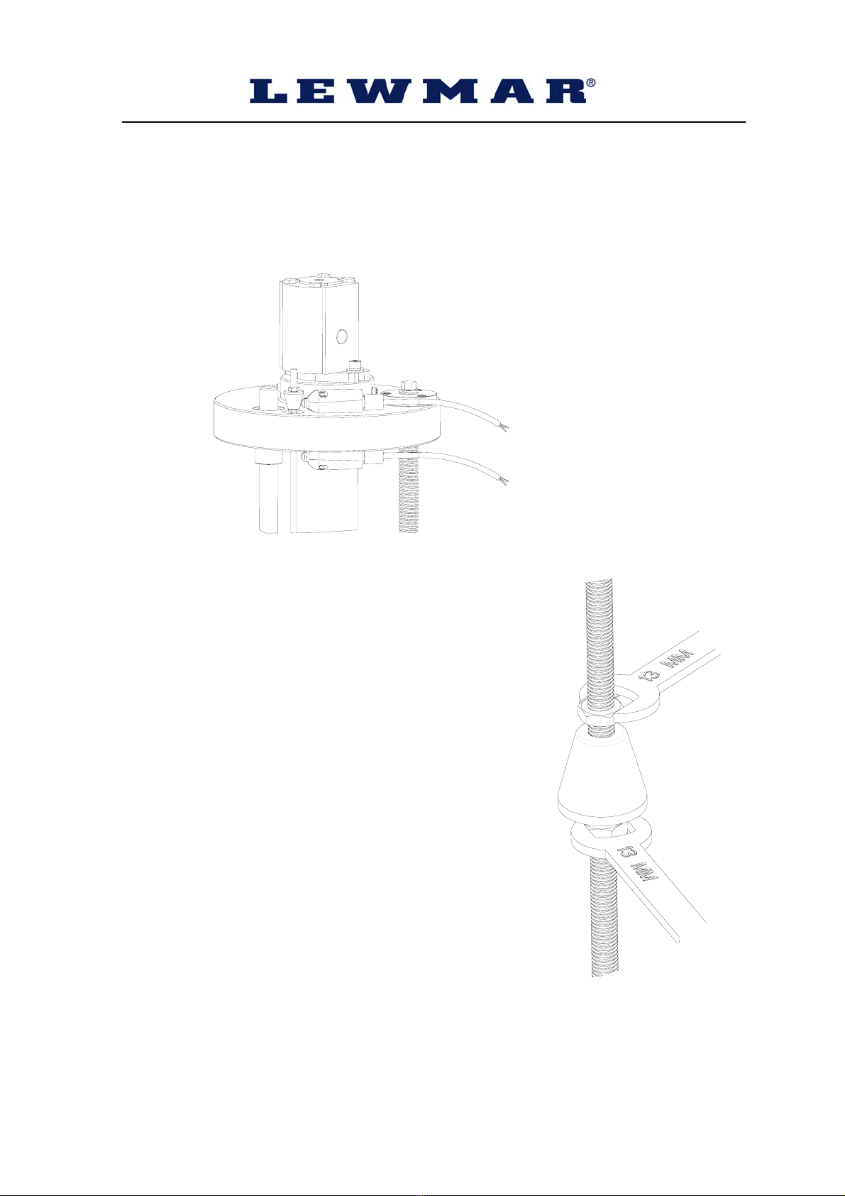
The Thruster is heavy so when lifting the Thruster unit from its packing case,
ensure that adequate lifting strops are used. The Thruster should not be lifted
by its lead screw assembly or propeller shroud. Extra caution should be used
to avoid damaging these parts, the micro switches and control box. When
moving the Thruster, ensure that the seating surfaces of the main housing are
protected against potential damage. The control box is secured to the
Thruster for protection during transit. A picture is included in the transport box
showing advised lifting method.
2.1.3 Fitting into the hull
The thruster requires a watertight compartment to be constructed within the
hull to house the shroud assembly, with an opening in the bottom of the hull
for the shroud to be lowered through.
The top of this watertight compartment is to act as the mounting seat for the
thruster base plate. This watertight compartment must be designed to take the
weight of the thruster, the transfer of thrust to the hull and any additional
forces created while the vessel is in motion. It is recommended that this is
carried out by a qualified navel architect.
When planning the Hull piece cut-out and watertight box, it is important that
the box gives adequate all-round clearance for the shroud of approx 5-10mm
(3/16-3/8”). Once the Thruster seating support has been fabricated and a
suitable hole has been cut in the hull, the Thruster can be installed.
Seat the unit down on a thin gasket of closed cell neoprene or a suitable
sealing compound. The base plate is pre-drilled with 8.5mm holes (250 VRTT)
or 10.5 holes (300 VRTT) see unit diagrams. It is recommended that stainless
steel bolts of property class 70 are used with nuts, plain washers and locking
washers. If fitting into an aluminium hull the base plate may be welded to the
watertight box. The thruster base plate is corrosion resistant 5083-T6.
The VRTT Thruster is supplied in the retracted position for ease of
transportation. The Thruster will need to be lowered once located, to have the
hull faring fitted. To lower the Thruster, either energise the raise/lower motor
or by using the mechanical lead screw (refer to Manual Raise/Lower section
for details).
Usually, the hull piece that has been cut out of the hull would be re-used to
provide the Thruster closing plate. This can be attached to the ribs moulded
into the tunnel shroud. The raise lower motor can take a hull piece up to 50kg
(110lbs). If additional bolts are being used, ensure that the bolt heads do not
foul the propeller tips inside the shroud. A landing or register (see diagram
below) should be moulded into the hull cut out, to allow the hull closing piece
to 'locate' when the Thruster is fully retracted. This is to prevent water flooding

5
the box at high pressure potentially damaging the gasket/seal and to eliminate
load being applied to the Thruster leg when the vessel is pounding at sea.
A sealing gasket is recommended between the closing plate and hull register.
This should be of a resilient material that will not cause sticking of the closing
plate and undue load on the raise/lower mechanism.

6
2.1.4 Raise/Lower Setting
The limit switches are factory set at a pre-determined safe setting and will
require adjustment during installation. The Limits switches are activated by the
adjustable stops.
The stops can be adjusted by loosening the lock
nuts either side of the stop with a 13mm spanner,
adjusting and re-tightening sufficient to stay in
position but not crush the plastic stop. It is
suggested that to guarantee trouble free operation
that a thread locking compound (i.e. Loctite 243)
is applied to the nuts on final setting.
When raised ensure that the limit switch actually
'makes' when the Thruster is fully retracted or
deployed, otherwise power will be left on the
Raise/Lower motor applying unnecessary stress
to the shroud / closing plate assembly.
When in the lowered position make sure that the
top plate does not make contact with the top face
of the lower housing. Failure to do this will cause
undue loading and prevent the raising of the
thruster.

7
2.1.5 Painting/protection
The Thruster base plate is supplied bare aluminium ready for anti-fouling.
There are 6 anodes fitted to the under water area, 2 on the propeller shafts
and 4 mounted directly on to the base plate, these must not be painted or
anti-fouled as this is will prevent them from protecting the unit. The underside
of the installation plate must be treated with an appropriate primer and
antifoul/paint as this is part of the corrosion protection system. Hub (bronze or
aluminium check version) and propeller may be anti-fouled. Always use the
appropriate anti-fouling that is compatible with surface being covered, refer to
antifoul/paint manufacturers instructions ensuring a through coverage of all
exposed surfaces. The shroud comes pre-gel coated and generally does not
need any additional coatings, however this is at the installer’s discretion.
Under no circumstance should any paints or anti-fouls be applied to the
stainless steel main leg.
NOTE:-
The installation of bars or grids across the tunnel entrance will have
an effect on the thruster performance.
They would need to be checked regularly and be removable for
maintenance.
Any foreign body that passes through the bars may cause additional
damage, as it won’t have an easy escape.

8
2.2 Thruster Main Drive Installation
2.2.1 VRTT Hydraulic
Flow and Pressure requirements
250VRTT - 15kw output
300VRTT - 22.5kw output
(16.8cc Rev Motor)
Flow = 53 l/min
Pressure = 190 bar (∆P)
(26cc Rev Motor)
Flow = 82 l/min
Pressure = 122 bar (∆P)
(26cc Rev Motor)
Flow = 72 l/min
Pressure = 210 bar (∆P)
(30cc Rev Motor)
Flow = 82 l/min
Pressure = 182 bar (∆P)
The hydraulic motors are supplied pre-tested with female ports and blanking
caps.
Ensure the correct pipe bore sizes/pressure ratings are installed as per
hydraulic requirements, refer to a competent hydraulic installer if in doubt.
Hydraulic motor ports 250 & 300 VRTT
A + B = 3/4” BSP
Drain = 1/4” BSP
NOTE: Motor Drain line must be connected
Equipment should be accessible to allow for routine maintenance, oil changes
etc. Keep tight bends and hose couplings to a minimum wherever possible.
Where hoses pass through bulkheads or near sharp edges, ensure pipe
clamps or additional shielding of the hose is undertaken to reduce the risk of
chaffing.
Hydraulic units must be checked for stray current along the supply hoses. If
found the motor must be fitted with correctly rated and sized insulated hoses.
Lewmar cannot accept responsibility for corrosion caused by stray voltage.
When first operating the Thruster, pulse the controller to charge (fill) the
hydraulic motor.

9
2.2.2 VRTT Electric
59127100 – VRTTE 24Vdc. This thruster is 24Vdc only and requires a main
high current supply to the main drive thruster motor and a separate 24Vdc
supply to the Raise/Lower control system.
59127110 – VRTTE 48Vdc. This thruster is 48V/24Vdc and requires a high
current 48Vdc supply to the main drive thruster motor, but a separate 24Vdc
supply to the Raise/Lower control system.
N.B. A Lewmar TT P/S Battery Switch box is supplied with this thruster to
enable the installer to double a 24Vdc supply to 48Vdc to the thruster using
additional batteries. – Please refer to the P/S Battery Switch installation
manual
A suitable Battery Isolator switch that can handle the thruster current and a
correctly sized fuse and fuse holder should be installed in the positive line.
The location should be easily accessible and known to the responsible person
on board.
The thruster battery switch must be switched off when no one is on board. It is
also advisable to switch it off when the thruster is not in use.
Install the battery/s as close as possible to the thruster, thus keeping the main
supply cables as short as possible, which will in turn keep the voltage drop to
the minimum.
Battery cold crank capacity should be at least equal to the thruster current.
The cables should be terminated with a ring terminal corresponding to the
motor studs – 10mm (3/8”) It is important that this termination is secure so that
the high current is transferred to the efficiently.
The minimum voltage at the motor when running should be 21V
Ensure insulating boots supplied with the unit are correctly fitted.
Note. If very large cables are used, discard supplied boots and fit appropriate
sized ones.
24Vdc:

10
48Vdc:
Refer to chart below for recommended Cable size based on maximum voltage
drop, depending on run and fuse required.
Lewmar also supply a fuse holder 589013.
Maximum total cable run Battery to Thruster and back
Cable CSA mm
35 50 70 95 120 150 Fuse Part No. Current
24V 9M 12M 21M 28M 36M 45M 400A 589010 520A
48V 21M 31M 42M 58M 75M - 250A 589008 340A
Cable AWG
2 1 0 00 000 0000
24V 29ft 41ft 52ft 66ft 84ft 105ft
48V 68ft 86ft 108ft 138ft 174ft 218ft
Electric bow thrusters use powerful electric motors, it is very important that
there is sufficient battery capacity and large enough cables for safe operation.
Using smaller than recommended batteries and cables will cause loss of
performance and may cause dangerous overheating.
Electric motors spark and run hot. Do not place near flammable or sealed
areas
The main battery must not be connected and power must not be switched on
until all covers and terminal protectors are correctly fitted.

11
When fitting the power cables to
the thruster make sure that the
cables are of sufficient length
and supported to allow for the
vertical movement of the
thruster
Incorrect installation of battery
cables or damage to connection
studs may result in a short to
the thruster body. Use the
examples on the next page to
check for a correct installation
on both +V and 0V battery
connections.
1. Correct installation. Supplied cable boots are used and no bare wires
exposed.
2. Live wire exposed! Correct the cable installation to match illustration 1
3. Terminal or motor is damaged. Contact Lewmar Ltd
4. Crimp inverted and is touching motor! Correct the cable installation to
match illustration 1

12
To prevent electrolytic corrosion or faults, the thruster motor body and
assembly must remain isolated from any power supply or grounds.
The installer can check for this using a multimeter in the following ways:
Test 1
With the negative not connected and the positive cable connected but with the
battery switch off or fuse removed. Use a continuity tester to check for a
connection between -ve stud and motor body and also between +ve stud and
motor body. In both cases the meter should give no indication of electrical
connection.
If a connection is measured between the +ve stud and the motor body, check
installation for cables or wires touching the assembly.
If a connection is measured between the –ve stud and the motor body,
remove any bonding straps to the assembly and check as before.

13
Test 2
With the battery applied: Use a voltmeter to test the voltage between the –ve
stud and the thruster motor body. If the supply voltage is measured,
disconnect power immediately and inspect the assembly for faulty installation
or damage.
IMPORTANT:
- Do not run the thruster out of the water, even for a few seconds,
the motor will overspeed by 300% causing damage to the seals etc.
and invalidate the warranty
- Any foreign object in contact with an operating propeller will cause
serious injury or damage and invalidate the warranty.
- Thrusters must not be installed in ‘wet’ areas or areas where
splashing is likely, damage to the electric motor may occur.

14
2.3 Thruster Electrical Control Installation
The 250/300 VRTT thruster is supplied with a Raise/Lower control box pre-
wired to the thruster limit switches, raise/lower motor and main drive motor
control (VRTTE only). The operation and factory fitting of the control box and
raise/lower assembly is tested prior to shipment.
A flying lead is supplied for connection of the power supply to the control box
Input power supply required: 24VDC 5A nominal.
This must be from a separate source to that used by the main drive motor if
installing a VRTTE. Note also that the supply must be suitable to handle a dc
motor inrush current of 45A for 10mS.
The control box is fitted with a circuit breaker, which is sized specifically such
that it will trip if an obstruction is encountered in the raise/lower mechanism
during operation.
This control box is supplied with a mounting bracket for ease of installation.
The cables that are pre-fitted to the box have an excess of length to aid the
installer in finding a suitable location.
Be aware when mounting this box that the cables fitted to the limit switch and
drive motor (VRTTE) will require enough play to allow for the raising and
lowering of the thruster assembly during normal operation.
VRTTH only:

15
VRTTE only:
The control connections available for customer installation are as follows
1 – Power supply to raise/lower control switches & lamps.
2 – Switched (latched) power in to box to enable raise/lower control.
3 – Switched (momentary) power signal in to initiate a thruster raise operation.
4 – Switched (momentary) power signal in to initiate a thruster lower
operation.
5 – OV supply to raise/lower control switches & lamps.
6 & 7 – Volt-free contact (5Amax) Closed circuit when the thruster is in the UP
position.
8 & 9 – Volt-free contact (5Amax) Closed circuit when the thruster is in the
DOWN position.
10 & 11 - Volt-free contact (5Amax) Closed circuit when the thruster is in the
DOWN position. Not available on VRTTE
Note these connections are made to a two part terminal block that can be
removed from the PCB to aid connection of wiring.
This control box is for the operation of the thruster raise/lower mechanism
only and does not control the hydraulic/electric main thruster drive.

16
A user interface control panel for controlling the raise/lower mechanism and
main thruster drive has been designed by Lewmar Ltd specifically for this
thruster and may be ordered separately, part number 58400612:
The panel dimensions are 100mm X 85mm. And is rated IP67 above the
panel when installed correctly with the use of a suitable gasket or sealing
compound.
Loom 1
Loom 2
The panel is supplied pre-wired with two colour coded looms: Loom 1 for
direct interface with the VRTT control box and Loom 2 for either direct
interface to the VRTTE main drive motor control (black box) or for hydraulic
valve control.
The colour coding is as follows:
Loom 1:
Wire Description Connector Pin
White Joystick Switch Common 4
Loom 2:
Grey Thrust to PORT Signal 3
Blue Thrust to STBD Signal 2
Wire Description Control Box
Connections
Yellow Raise Switch Position Indicator 7
White Lower Switch Position Indicator 9
Brown On/Off switch / Control Enable 2 & 6
Red +V Panel Supply 1 & 8
Black 0V Indicator Common 5
Grey Lower Switch Signal 4
Orange Raise Switch Signal 3

17
Loom 1 of the VRTT control panel is interfaced with the VRTTE main electric
drive motor ‘Black Box’ control unit using standard Lewmar TT thruster control
loom connecting cables sourced separately:
The 7-way control loom (2) for the raise/lower control of the thruster must be
sourced by the installer. This loom must have a minimum current carrying
capacity of 1 Amp and should meet all relevant standards and regulations.
Note the VRTTE has additional wiring fitted to the thruster assembly and
VRTT control box that is used to disable the main drive control for when the
thruster is not in the lowered position.
Cable Length Part Number
2M 589021
7M 589016
10M 589017
14M 589018
18M 589019
22M 589020

18
VRTTE Main Drive Control & Power Connections
24Vdc:

19
48Vdc:
This manual suits for next models
4
Table of contents
Other Lewmar Outboard Motor manuals