Lexicomm TMS3 User manual

Lexicomm Network TMS3 EVCS
Master Station Quick Start Guide
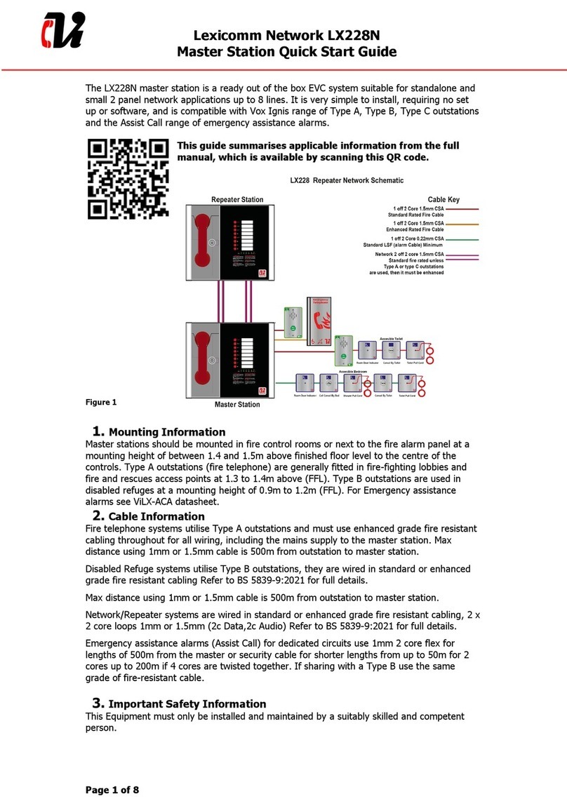
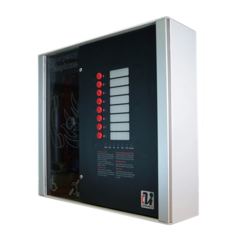
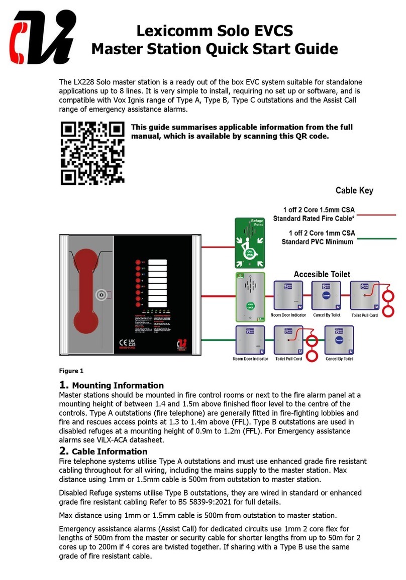
The ViLX-TMS3-W-8/0 master station/ViLX-ACM3-8 Assist Call master is part of the Lexicomm
Network EVC system suitable for medium to large applications up to 512 lines. It is
compatible with Vox Ignis range of Type A, Type B, Type C outstations and the Assist Call
range of emergency assistance alarms.
This guide summarises applicable information from the full
manual, which is available from the Vox-Ignis website by
scanning this QR code. The installation and commissioning
manual and the User Guide are contained on the micro SD card
that is fitted to the rear of the ViLX-TMS3-W-8/0 master
station display PCB.
Figure 1
1. Important Safety Information
This Equipment must only be installed and maintained by a suitably skilled and competent
person.
This Equipment is defined as Class 1 in EN IEC62368-1:2020+A11:2020 (Low Voltage
Directive) and must be EARTHED.
Caution
Indoor Use Only
Warning
Shock Hazard-
Isolate Before Opening
Warning
TO REDUCE THE RISK OF FIRE OR
ELECTRIC SHOCK, DO NOT EXPOSE THIS
UNIT TO RAIN OR MOISTURE
Warning
THIS UNIT MUST BE EARTHED
Warning
NO USER SERVICEABLE PARTS
Figure 2

Each ViLX-TMS3-W-8/0 Master Station requires local isolation with verification as per the
Electricity at Work Regulations 1989, returning to a B6A breaker clearly marked
“EMERGENCY VOICE COMMUNICATION SYSTEM. DO NOT TURN OFF”.
2. Anti-static handling guidelines
Make sure that electrostatic handling precautions are taken immediately before handling PCBs
and other static sensitive components.
Before handling any static-sensitive items, operators should get rid of any electrostatic charge
by touching a sound safety earth. Always handle PCBs by their sides and avoid touching any
components.
3. Battery Information
In the event of mains failure BS 5839-9:2021 requires battery backup for 24 hours standby
and 3 hours operation thereafter.
A ViLX-TMS3-W-8/0 Master Station requires one number 12V 7AH valve regulated sealed
lead acid battery. The battery is not supplied with the ViLX-TM3-W-8/0 Master Station.
Safety Information:
Sealed Lead Acid batteries contain sulphuric acid which can cause burns if
exposed to the skin. The low internal resistance of these batteries mean
large currents will flow if they are accidentally short-circuited causing burns
and a risk of fire.
Exercise caution when handling batteries.
Power Up Procedure:
Always apply mains power before connecting batteries. When connecting
batteries, always connect the Positive (Red +) terminal first.
Power Down Procedure
Disconnect the batteries before removing the mains power. When
disconnecting batteries, always remove the Negative (Black –) terminal first.
4. Mounting Information
Master stations should be mounted in fire control rooms or next to the fire alarm panel at a
mounting height of between 1.4 and 1.5m above finished floor level to the centre of the
controls. Type A outstations (fire telephone) are generally fitted in fire-fighting lobbies and
fire and rescues access points at 1.3 to 1.4m above (FFL). Type B outstations are used in
disabled refuges at a mounting height of 0.9m to 1.2m (FFL). For Emergency assistance
alarms see ViLX-ACA datasheet.
Use the 2.5mm AF Hex Key supplied to open the right-hand front cover. Use suitable fixings
to mount the back box, there is no need to remove any PCBs or brackets to enable fixing of
the enclosure.
Figure 3
Unused knockouts must be left unopened to comply with the Low Voltage Directive.
Accidentally knocked out holes should be blanked off.

The ViLX-TMS3-W-8/0 Master Station weighs 6kg with batteries, so care should be taken to
securely mount the Station on stud walling.
Figure 4
5. Wiring
5.1 Cable Information
Fire telephone systems utilise Type A outstations and must use enhanced grade fire resistant
cabling throughout for all wiring, including the mains supply to the master station. Maximum
distance using 1mm or 1.5mm cable is 500m from outstation to master station.
Disabled Refuge systems utilise Type B outstations, they are wired in standard or enhanced
grade fire resistant cabling Refer to BS 5839-9:2021 for full details.
Max distance using 1mm or 1.5mm cable is 500m from outstation to master station.
Emergency assistance alarms (Assist Call) for dedicated circuits use 1mm 2 core flex for
lengths of 500m from the master or security cable for shorter lengths from up to 50m for 2
cores up to 200m if 4 cores are twisted together. If sharing with a Type B use the same
grade of fire-resistant cable.
5.2 Network Wiring
The network is dual redundant fault tolerant with short circuit isolation included within all
compatible panels, It is important to wire the network as a ring, cabling must be 2×2 core
loops (Audio 2c, Data 2c) therefore there will be 4×network cables at each panel.
Battery Space
1x 12V 7AH
VRSLA
Earth
Block
Mains
IN
LinesLines
Line Line
Dual Line Card
(c) 202 0 Vox Ig nis Limited
PViLXEX 6002-0 4
0 + +0
Line Line
+0+0
Line Line
Dual Line Card
(c) 202 0 Vox Ig nis Limited
PViLXEX 6002-0 4
0 + +0
Line Line
+0+0
Line Line
Dual Line Card
(c) 202 0 Vox Ig nis Limited
PViLXEX 6002-0 4
0 + +0
Line Line
+0+0
Line Line
Dual Line Card
(c) 202 0 Vox Ig nis Limited
PViLXEX 6002-0 4
0 + +0
Line Line
+0+0
30
30
350
Enab le
Display
PSU
ogram
Fault In Use
Master
Handset
LexicommNetwork Exchan ge
(C)202 2 Vox Ignis Limited
PViLXEXN 6001-03
Network Ex change R3
Off Hook
Address
A
Network IN
B C D A BC D
Network OUT
Fault In Use Enable
Record
Mains supply
EVC connection
Network address
Network
connection
Relay
contacts

5.3 Network Address
The TMS3 master station factory default network address is 1, network address 2 is the
default address for a system expander panel. When additional panels are added to the
network, the next address will be address 3. It is not essential that network addresses run
sequentially, and a gap can be left in the address sequence, however this is less desirable
and makes fault finding more difficult.
This address is set by the dipswitches on the Exchange PCB as shown in Figure 4. The
address is a binary number given by the positions of dip switches 1 to 6, with valid addresses
lying between 1 and 64 inclusive. A full address list is available in the full manual.
Figure 5
6. Commissioning
The commissioning should be carried out by a competent person who has a basic knowledge
and understanding of the design and installation sections of BS 5839-9:2021 and has access
to the specification of the project.
6.1 Cable Checks
The 500V insulation tests should have been carried out by the installer and the results made
available to the commissioning engineer.
All cables should be correctly labelled.
Test field wiring and check for end-of-line 10kΩresistor on all line circuits. Check cables are
clear from any short or open circuits.
Connect outstation cables into Line Cards ensuring the Earth is sleeved and terminated into
the Earth block.
6.2 Network Set up
Configure relevant dipswitches for the network settings that may be required as per the set-
up section in this manual.
Connect the network cabling (if appropriate), ensuring Net OUT ABCD is correctly connected
to Net IN ABCD and the ring is continuous. Only Connect the Earth screen of the Net IN
cables.

Figure 6
6.3 Power Up
Power up the ViLX-TMS3 Master Station using mains only, fed via a double pole isolator local
to the panel fed from a dedicated circuit. The AC power indicator will be illuminated, and the
DC power indicator is extinguished. The PSU fault and General fault indicators will be
illuminated. There should be no line fault indicators illuminated.
If there are no line faults present, the battery may be connected. The DC power indicator will
be illuminated, and the PSU fault and General fault indicators are extinguished when battery
is connected.
If there are any line fault indicators illuminated, then the field wiring should be checked prior
to the battery being connected.
Repeat the power up section for any additional ViLX-EX8 Expander panels or additional ViLX-
TMS panels.
6.4 Site Configuration
Upload the site configuration from the Micro SD card (recommended) see section 7 in the
TMS3 Installation and Commissioning manual available in Download section at www.vox-
ignis.com or using the settings menus see section 8 of same manual.
As mentioned previously the default configuration is for 1 x ViLX-TMS3-W-0/8 and 1 x ViLX-
EX8 System expander panel, set up with 8 lines on each
If device missing or network faults are reported address these before continuing. Once
remedied re-upload the site configuration to ensure all panels are programmed
6.5 Site Testing
Lift the master handset receiver and listen for a cadence tone.
All outstations may be tested now, visit each outstation in turn and test that it is connected to
the correct Master Station or Expander panel and perform an intelligibility test. This test

should be conducted when the building has normal background noise levels. The intelligibility
test requires two personnel.
Where Assist Call is fitted, all pull cords in each circuit should be tested, acknowledged at the
panel, cancelled at the call location and the panel text checked. Ensure all controls and
indicators operate correctly.
When all outstation tests are complete, network cable checks should be performed to
ascertain correct operation by unplugging network cable to ensure the network is correctly
fault monitoring and continues to work with a single cable fault.
When complete the log may be retrieved from Micro SD card, saved as a spreadsheet, and
kept for record purposes.
7. Settings Menu
For a full description of the menus and features of the TMS3 master station, the full
installation and commission manual should be consulted.
Figure 7
All menus are accessed from the home screen as shown
in Figure 7. The screen shown has already been accessed
from the engineer code (1812). By pressing the settings
button the settings menu as shown in Figure 8 will
be accessed.
As can be seen there are many other menus shown, such
as:
Clock –Allows the user to edit the time and date
settings that are used across the network.
Test –Allows the user to perform a lamp and
buzzer test on the panel.
Load –Allows the user to load the configuration
from the Micro SD card.
Backup –Allows the user to back up the
configuration to the Micro SD card.
Settings –Allows the user to access the settings
menu to configure the system.
Figure 8
The additional engineering menus are shown on this
screen, a summary of the panel settings is displayed. By
pressing the button other panels on the network can
be navigated to, which gives access to their network and
line settings.
Lines –Allows the user to edit the line settings
on the network
PIN –Allows the user to change the passcodes
for both access levels on the TMS
Relays –Allows the user to configure the in-use
relay on the local exchange board
Language –Allows the user to change the
language of the TMS panel
Pager –Allows the user to configure the pager.
Only shown if the daughterboard is attached

Figure 9
The panel settings screen is shown by pressing the
icon on the settings screen.
At the top of the screen is the address and name of the
panel that is being configured. This panel can be changed
by pressing the and icons.
The panel type button selects which type of panel is
situated at the given panel address, highlighting in green
denotes panel selection.
Network monitoring is achieved by use of the toggles
which indicate if each port is monitored To meet BS
5839-9:2021, by net in and net out should be monitored,
as the network is wired in a ring.
Once configuration is changed, the save button is
shown. Pressing it will update the configuration for that
panel. Each panel must be saved separately.
Pressing the back button returns to Figure 8
without saving new configuration
Figure 10
The line settings screen is shown by pressing the
icon on the settings screen and allows the user to see the
monitoring for each line, and change any of the text
associated with the line
At the top of the screen is the address and name of the
panel that is being configured. This panel can be changed
by pressing the and icons.
A line is selected using the number buttons, with
indicating which line is the currently selected one.
Underneath the line select is the monitoring state of the
selected line. The states that are possible are:
No
No device is being monitored for
EVCS
Type A, Type B or Type C outstation
attached
Alarm
Emergency assistance alarm attached
Yes
Both outstation and assistance alarm
attached
Switch
Event mode switch input attached to line
Pressing the icon will bring up the line monitoring
screen and allow the user to configure the monitoring of
a given line, along with the call and alarm icons, and the
day and night settings.
The call name, alarm name, and fault name for the given
line are all shown and can be edited by pressing the
icon next to the desired text. All these pieces of text are
two lines of 20 characters.
Pressing the back button returns to Figure 8
without saving new configuration

WEEE
Compliant
Product
All information is believed to be correct at time of printing E&OE.
Vox Ignis operate a policy of continuous improvement; always confirm specification details before purchase.
ViOD00221/Rev2/JK
8. Operational Flowcharts
8.1 TMS Home/Menu Structure
8.2 TMS Settings Structure
9. What’s included
Remove the ViLX-TMS3 from its packing, and check the contents against the following list:
•ViLX-TMS3 Master Station.
•Quick Start Guide.
•Accessory pack with the following contents:-
o1 × 2.5mm AF Hex Key.
o1 × Battery Lead.
oEnd-of-Line 10kΩResistors, 2 per Line Card.
oUSB Micro SD Card reader.
oDoor Lock Key
Micro SD card is fitted to the rear of the display PCB, this is preloaded with factory default
configuration as previously described.
The Lexicomm Network EVCS is designed and manufactured in the UK by:
Vox Ignis Limited, Unit 27, NEBIC, Enterprise Park East, Sunderland, SR5 2TA.
www.vox-ignis.com
This manual suits for next models
1
Table of contents
Other Lexicomm Conference System manuals
Popular Conference System manuals by other brands

TANDBERG
TANDBERG D12817-05 user manual

Polycom
Polycom realpresence group 550 System Setup Sheet

AVer
AVer HVC series Quick installation guide

DIS
DIS CDS 4000 User manual & installation guide

Zenitel
Zenitel Phontech MPA 1600 Series User handbook

Siemens
Siemens SIMATIC NET S7-300-PROFIBUS CP 342-5 Equipment manual