Document PViLX228 7001-06 Rev 6 2017 Page 2 of 24
Table of Contents
1. Introduction...............................................................................................................................3
1.1 What is an Emergency Voice Communication System ..............................................................3
1.2 Suitability............................................................................................................................3
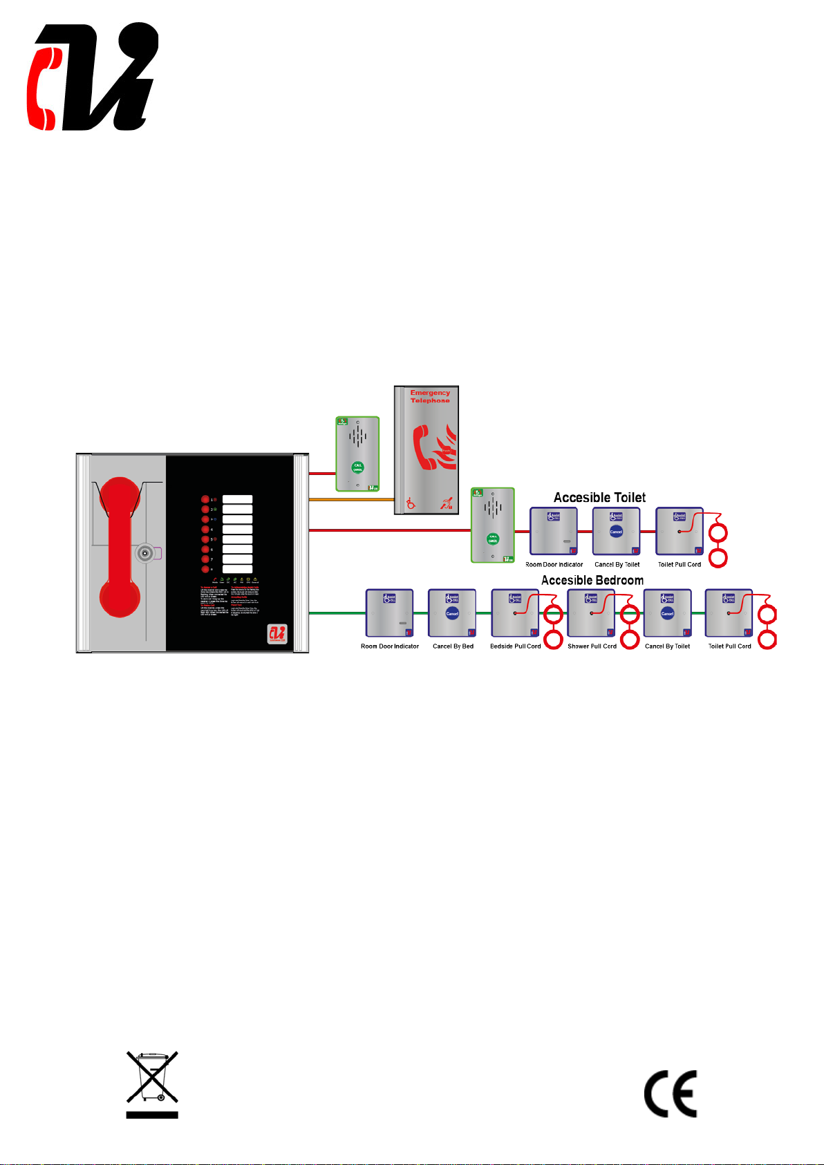
2. Product Overview.......................................................................................................................3
3. Important Safety Information......................................................................................................4
4. Unpacking the Unit.....................................................................................................................5
5. Installation ................................................................................................................................6
5.1 Connecting the ViLX-228 Master Station.................................................................................7
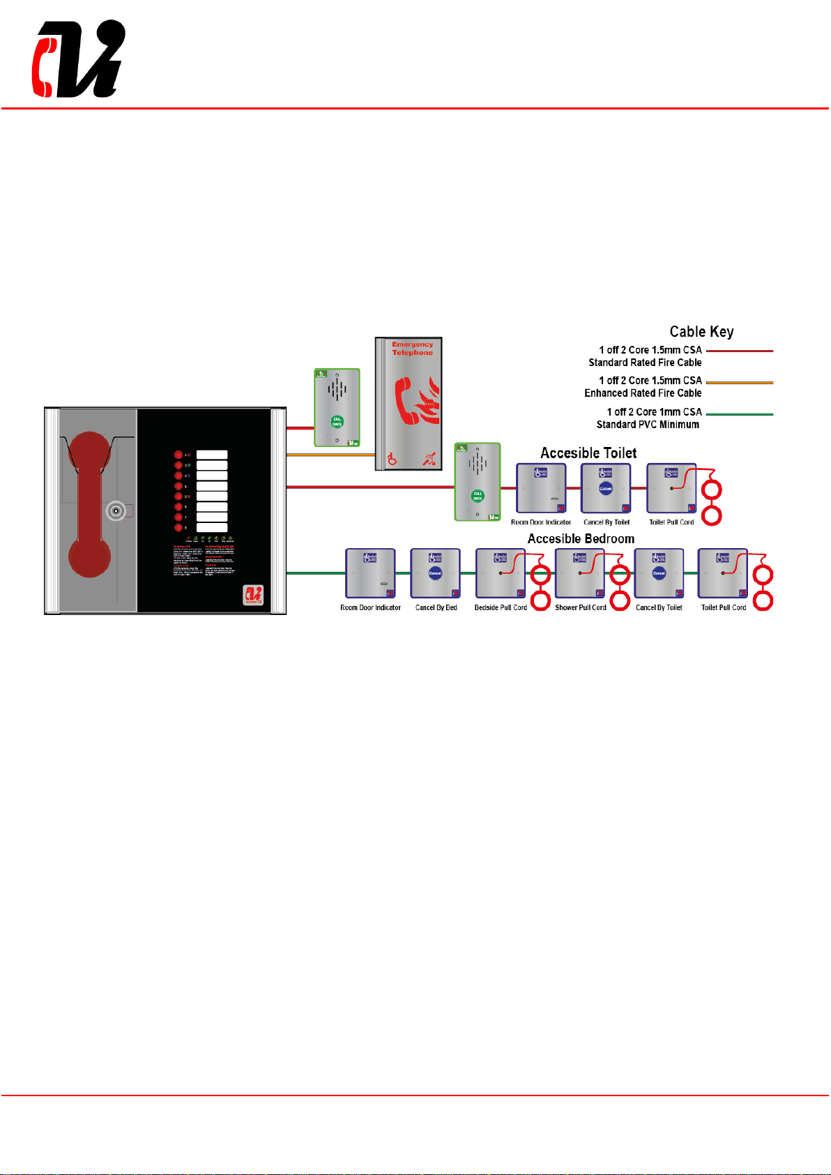
5.2 Planning the Wiring..............................................................................................................7
5.3 Cable and Wiring Guidance...................................................................................................7
5.3.1 Fire Telephone system ..................................................................................................7
5.3.2 Disabled Refuge EVC System .........................................................................................7
5.3.3 Combined Systems........................................................................................................7
5.3.4 “Assist Call” Emergency Assistance Alarm Systems...........................................................7
5.4 Cabling methods..................................................................................................................7
5.4.1 ViLX-228 Master Station Wiring ......................................................................................8
5.4.2 ViLX-228 Master/Repeater Stations wiring in ring.............................................................9
5.5 Mains Connection...............................................................................................................10
5.6 Battery Information............................................................................................................10
5.7 Outstation Connections.......................................................................................................10
5.7.1 Type A outstation........................................................................................................11
5.7.2 Type B outstation........................................................................................................11
5.7.3 ACA Accessible Toilet Kit..............................................................................................11
5.8 Auxiliary Connections .........................................................................................................12
5.9 Powering up procedure.......................................................................................................12
5.10 Powering down procedure.................................................................................................12
6. Set up procedure .....................................................................................................................13
6.1 ViLX-228 Master Station Display PCB Dipswitch Settings ........................................................13
6.2 Adding a Line Card.............................................................................................................14
6.3 Removing a Line card.........................................................................................................14
6.4 Adding a ViLX-228 Repeater Station.....................................................................................14
ViLX-228 Master Station Exchange PCB Dipswitch Settings ..........................................................15
7. System Menus .........................................................................................................................16
7.1 Fault Accept ......................................................................................................................16
7.2 Panel Indicator Test ...........................................................................................................16
7.3 Extended Fault Menu..........................................................................................................16
7.4 Line Identify......................................................................................................................16
7.5 Engineer Walk Test ............................................................................................................17
7.6 Remote Signal Delay Timer.................................................................................................17
7.7 In Use Relay Options..........................................................................................................18
8. Operation................................................................................................................................18
8.1 Receiving a call..................................................................................................................18
8.2 Making a call .....................................................................................................................18
8.3 Ending a call......................................................................................................................18
8.4 Putting a call on hold..........................................................................................................18
8.5 Conference Call..................................................................................................................18
8.6 Acknowledging “Assist Call” alarms......................................................................................19
8.7 Accepting Faults.................................................................................................................19
8.8 Panel Indicator Test ...........................................................................................................19
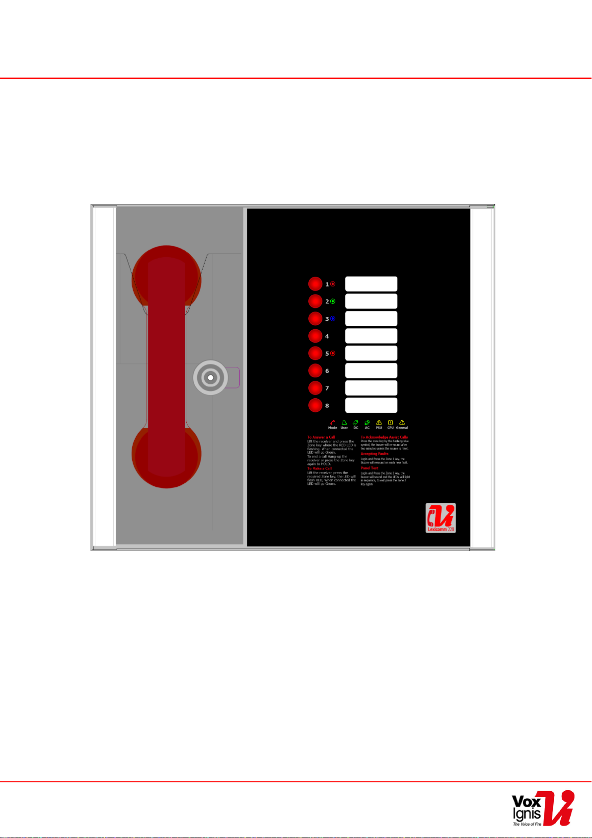
9. Indications and Controls ...........................................................................................................19
9.1 Mode Indicator Summary....................................................................................................19
9.2 Power supply and CPU indicator Summary............................................................................20
9.3 User Indicator Summary.....................................................................................................20
9.4 Zone indicator summary .....................................................................................................20
10. Commissioning procedure .......................................................................................................21
11. Maintenance ..........................................................................................................................21
12. Outstation zone template........................................................................................................22
13. Technical Specification............................................................................................................24