Lexus RX 400h Hybrid 2007 User manual

Hybrid
2007Model
© 2005 Toyota Motor Corporation
All rights reserved. This document may not be
altered without the written permission of Toyota Motor Corporation.
06RX 400hERG REV – (05/27/05)

-i-
Foreword
In April 2005, Lexus released the Lexus RX 400h gasoline-electric
hybrid vehicle in North America. Except where noted in this guide,
basic vehicle systems and features for the RX 400h are the same as
those on the conventional, non-hybrid, Lexus RX 350. To educate and
assist emergency responders in the safe handling of the RX 400h hybrid
technology, Lexus published this RX 400h Emergency Response Guide.
High voltage electricity powers the electric motors, generator,
inverter/converter, and power steering. All other automotive electrical
devices such as the headlights, radio, and gauges are powered from a
separate 12-Volt battery. Numerous safeguards have been designed
into the RX 400h to help ensure the high voltage, approximately 288-
Volt, Nickel Metal Hydride (NiMH) Hybrid Vehicle (HV) battery pack
is kept safe and secure in an accident.
The RX 400h utilizes the following electrical systems:
•Maximum 650-Volts AC
•Nominal 288-Volts DC
•Nominal 42-Volts DC
•Nominal 12-Volts DC
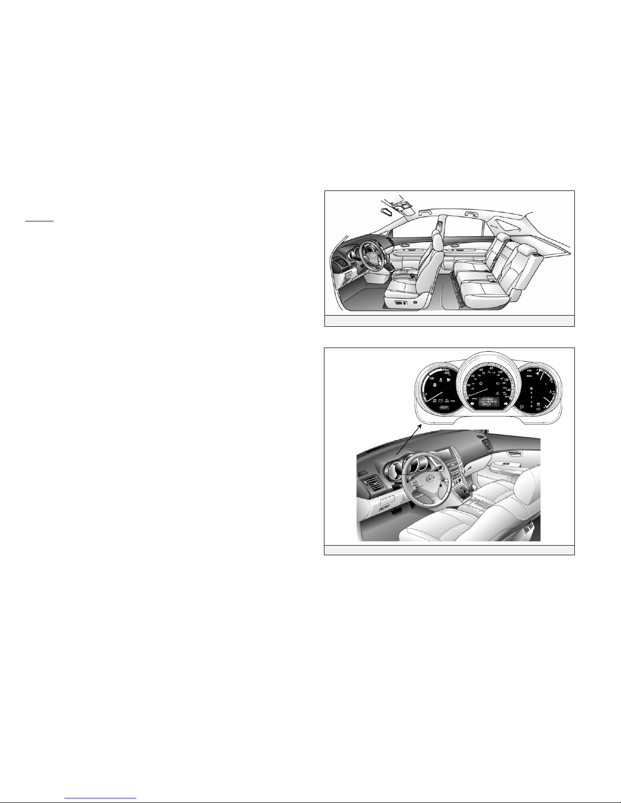
RX 400h Features:
•Adoption of Hybrid Synergy Drive as the name for the Lexus
Gasoline - Electric Hybrid System.
•Hybrid Synergy Drive includes a boost converter in the inverter
assembly that boosts to 650-Volts the available voltage to the
electric motors.
•The high voltage hybrid vehicle battery pack rated at 288-Volts.
•A high voltage motor driven air conditioning compressor rated at
288-Volts
•A high voltage Electric Power Steering (EPS) assist motor rated at
42-Volts.
•Body electrical system rated at 12-Volts negative chassis ground.
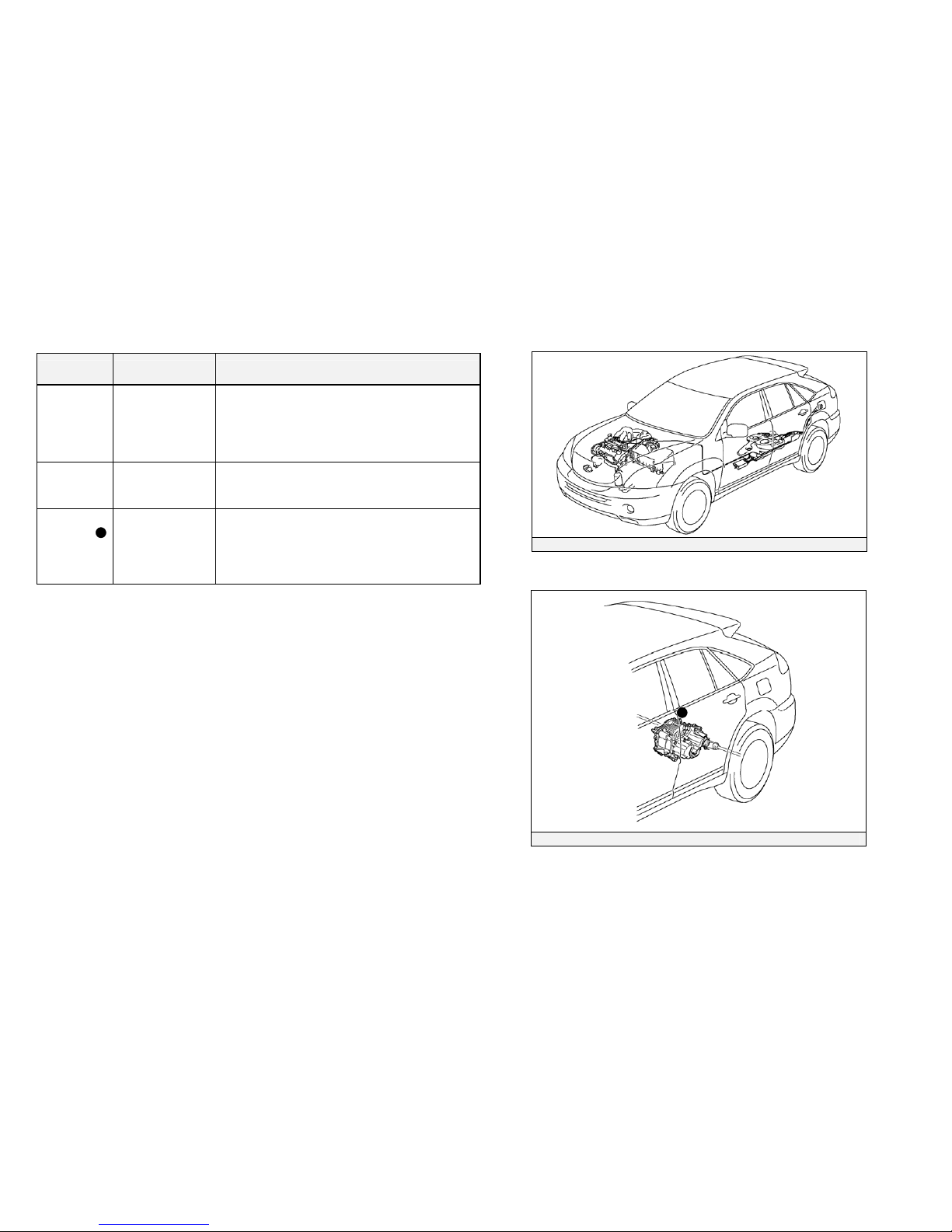
•Both two-wheel-drive (2WD) and four-wheel-drive (4WD)
configurations are available.
•4WD models include an additional 650-Volt electric motor to drive
the rear wheels.
•Supplemental Restraint System (SRS) - dual stage frontal airbags,
driver knee airbag, front seat side airbags, curtain shield airbags,
and front seat belt pretensioners.
High voltage electrical safety is an important factor in the emergency
handling of the RX 400h Hybrid Synergy Drive system. It is important
to recognize and understand the disabling procedures and warnings
throughout the guide.
Additional topics contained in the guide include:
•Lexus RX 400h identification.
•Major Hybrid Synergy Drive component locations and descriptions.
•Extrication, fire, recovery, and additional emergency response
information.
•Roadside assistance information.
2007Model Year RX 400h
By following the information in this guide, emergency responders
should be able to mitigate a rescue involving the Lexus RX 400h
hybrid vehicle safely.

-ii-
Table of Contents Page
About the RX 400h 1
RX 400h Identification 2
Hybrid Synergy Drive Component Locations & Descriptions 6
Hybrid Synergy Drive Operation 9
Hybrid Vehicle (HV) Battery Pack and Auxiliary Battery 10
High Voltage Safety 11
SRS Airbags & Seat Belt Pretensioners 13
Emergency Response 15
Extrication 15
Fire 18
Overhaul 19
Recovery/Recycling NiMH HV Battery Pack 19
Spills 20
First Aid 20
Submersion 21
Roadside Assistance 22

-1-
About the RX 400h
The RX 400h is the first gasoline-electric hybrid vehicle for Lexus. The
gasoline-electric hybrid system has been named Hybrid Synergy Drive.
Hybrid Synergy Drive means that the vehicle contains a gasoline engine
and an electric motor for power. Two energy sources are stored on
board the vehicle:
1. Gasoline stored in the fuel tank for the gasoline engine.
2. Electricity stored in a high voltage Hybrid Vehicle (HV) battery
pack for the electric motor.
The result of combining these two power sources is improved fuel
economy and reduced emissions. The gasoline engine also powers an
electric generator to recharge the battery pack; unlike a pure all electric
vehicle, the RX 400h never needs to be recharged from an external
electric power source.
Depending on the driving conditions one or both sources are used to
power the vehicle. The following illustration demonstrates how the RX
400h operates in various driving modes.
On light acceleration at low speeds, the vehicle is powered by the
electric motor. The gasoline engine is shut off.
During normal driving, the vehicle is powered mainly by the
gasoline engine. The gasoline engine is also used to recharge the
battery pack.
During full acceleration, such as climbing a hill, both the gasoline
engine and the electric motor power the vehicle.
During deceleration, such as braking, the vehicle regenerates the
kinetic energy from the wheels to produce electricity that recharges
the battery pack.
While the vehicle is stopped, the gasoline engine and electric motor
are off, however the vehicle remains on and operational.

-2-
RX 400h Identification
In appearance, the 2007RX 400h is nearly identical to the
conventional, non-hybrid Lexus RX 350. The RX 400h is a 5-door
Luxury Utility Vehicle. Exterior, interior, and engine compartment
illustrations are provided to assist in identification.
The alphanumeric 17 character Vehicle Identification Number (VIN) is
provided in the front windshield cowl, driver door post, and under the
front passenger seat.
Example VIN: JTJGW31U840020208 (2WD)
JTJHW31U850011201 (4WD)
An RX 400h is identified by the first 6 alphanumeric characters;
JTJGW3 (2WD) and JTJHW3 (4WD).
VIN Plate Locations

-3-
RX 400h Identification (Continued)
Exterior
logos on the rear hatchback door.
Gasoline fuel filler door located on the driver side rear quarter panel.
Exterior Driver Side View
Exterior Front View Exterior Rear View
Exterior Rear and Driver Side View

-4-
RX 400h Identification (Continued)
Interior
Instrument cluster (speedometer, fuel gauge, warning lights), located in
the dash behind the steering wheel, is different than the one on the
conventional, non-hybrid RX 350.
In place of a tachometer, a power meter showing kW output is used.
NOTE:
If the vehicle is off, the instrument cluster gauges will be “blacked out”,
not illuminated.
Interior View
Instrument Cluster View

-5-
RX 400h Identification (Continued)
Engine Compartment
3.3-liter aluminum alloy gasoline engine.
High voltage inverter/converter assembly with
logos on the cover.
Engine Compartment View
Logos on Cover

-6-
Hybrid Synergy Drive Component Locations & Descriptions
Component Location Description
12-Volt
Auxiliary
Battery
Engine
Compartment Lead-acid battery powers all low voltage
electrical equipment.
Hybrid
Vehicle
(HV) Battery
Pack
Cabin Area,
Mounted to Cross
Member and
Under Rear Seat
288-Volt Nickel Metal Hydride (NiMH)
battery pack consisting of 30 low voltage (9.6-
volt) modules connected in series.
Power
Cables Under Carriage
and Engine
Compartment
Orange colored power cables carry high
voltage Direct Current (DC) between the HV
battery pack, inverter/converter, and A/C
compressor. Also carries 3-phase Alternating
Current (AC) between inverter/converter,
motor, and generator.
Inverter/
Converter Engine
Compartment Boosts and inverts the high voltage electricity
from the HV battery pack to 3-phase AC
electricity that drives the electric motor. The
inverter/converter also converts AC electricity
from the electric generator and motor
(regenerative braking) to DC that recharges the
HV battery pack.
Gasoline
Engine Engine
Compartment Provides two functions: 1) powers vehicle; 2)
powers generator to recharge the HV battery
pack. The engine is started and stopped under
control of the vehicle computer.
Front
Electric
Motor
Engine
Compartment 3-phase high voltage AC permanent magnet
electric motor contained in the front transaxle.
Used to power the front wheels.
Electric
Generator Engine
Compartment 3-phase high voltage AC generator contained
in the front transaxle. Used to recharge the HV
battery pack.
A/C
Compressor Engine
Compartment 3-phase high voltage AC electrically driven
motor compressor.
Hybrid Synergy Drive Components
*:Only on models with 4WD system
Components (Top View) and High Voltage Power Cables
11
*

-7-
Hybrid Synergy Drive Component Locations & Descriptions
(Continued)
Component Location Description
EPS DC-DC
Converter
Underneath the
cargo area by the
spare tire
Converts 288-Volts from the HV battery pack
to 42-Volt. Yellow-colored cables conduct the
42-Volt power underneath the vehicle floor pan
to the power steering rack via the EPS ECU,
located in the engine compartment.
Fuel Tank
and Fuel
Lines
Undercarriage,
Driver Side Fuel tank provides gasoline via a single fuel
line to the engine. The fuel line is routed along
the driver side under the floor pan.
Rear Electric
Motor
(4WD Model
Only)
Rear Sub-Frame 3-phase high voltage AC permanent magnet
electric motor contained in the rear transaxle
used to power the rear wheels.
Fuel Tank and Fuel Line Components
Rear Electric Motor
11
11

-8-
Hybrid Synergy Drive Component Locations & Descriptions
(Continued)
Key Specifications:
Gasoline Engine: 208 hp, 3.3 liter Aluminum Alloy Engine
Electric Motors
Front:
Rear:
165hp, Permanent Magnet Motor
67hp, Permanent Magnet Motor
Transmission: Automatic Only
HV Battery: 288-Volt Sealed NiMH
Curb Weight 4,365lbs / 1,981 kg
Fuel Tank: 17.2 gals / 65 liters
Fuel Economy 31 / 27 (City/Hwy) miles/gal
7.5 / 8.1 (City/Hwy) liters/100km
Frame Material:
Body Material: Steel unibody
Steel panels
Steel Unibody

-9-
Hybrid Synergy Drive Operation
Once the READY indicator is illuminated in the instrument cluster, the
vehicle may be driven. However, the gasoline engine does not idle like
a typical automobile and will start and stop automatically. It is
important to recognize and understand the READY indicator provided
in the instrument cluster. When lit, it informs the driver that the vehicle
is on and operational even though the gasoline engine may be off and
the engine compartment is silent.
Vehicle Operation
•With the RX 400h, the gasoline engine may stop and start at any time
while the READY indicator is on.
•Never assume that the vehicle is shut off just because the engine is off.
Always look for the READY indicator status. The vehicle is shut off
when the READY indicator is off.
•The vehicle may be powered by:
1. The electric motor only.
2. The gasoline engine only.
3. A combination of both the electric motor and the gasoline engine.
•The vehicle computer determines the mode in which the vehicle operates
to improve fuel economy and reduce emissions. The driver cannot
manually select the mode.
Instrument cluster READY Indicator

-10-
Hybrid Vehicle (HV) Battery Pack and Auxiliary Battery
The RX 400h contains a next generation high voltage, Hybrid Vehicle
(HV) battery pack and a low voltage auxiliary battery. The HV battery
pack contains non-spillable, sealed Nickel Metal Hydride (NiMH)
battery modules and the auxiliary battery is a typical automotive lead-
acid type.
HV Battery Pack
•The HV battery pack is enclosed in a metal case and is rigidly mounted to
the cabin area floor pan cross member under the rear seat. The metal case
is isolated from high voltage and concealed by a cover in the cabin area.
•The HV battery pack consists of 30 low voltage (9.6-Volt) NiMH battery
modules connected in series to produce approximately 288-Volts. Each
NiMH battery module is non-spillable and sealed in a metal case.
•The electrolyte used in the NiMH battery module is an alkaline of
potassium and sodium hydroxide. The electrolyte is absorbed into the
battery cell plates and will form a gel that will not normally leak, even in
a collision.
•In the unlikely event the battery pack is overcharged, the modules vent
gases directly outside the vehicle through a vent hose.
HV Battery Pack
Battery pack voltage 288-Volts
Number of NiMH battery modules in the pack 30
NiMH battery module voltage 9.6-Volts
NiMH battery pack dimensions 25 x 43 x 7 in
(63 x 108 x 18 cm)
NiMH battery Pack weight 152.1 lbs
(69 kg)
Components Powered by the HV Battery Pack
•Front Electric Motor •Rear Electric Motor (with 4WD)
•Inverter/Converter •A/C Compressor
•Electric Generator •Power Cables
•Electric Power Steering
HV Battery Pack Recycling
•The HV battery pack is recyclable. Contact the nearest Lexus dealer or
Lexus Roadside Assistance at:
United States: (800) 255-3987, Canada: (800) 265-3987
Auxiliary Battery
•The RX 400h also contains a lead-acid 12-Volt battery. The 12-Volt
auxiliary battery powers the vehicle electrical system similar to a
conventional vehicle. As with conventional vehicles, the auxiliary battery
is grounded (negative pole) to the metal chassis of the vehicle.
•The auxiliary battery is located in engine compartment area.
288-Volt HV Battery Pack 12-Volt Auxiliary Battery in Engine
Compartment.
HV Battery Pack Mounted in Cabin Area

-11-
High Voltage Safety
The HV battery pack powers the high voltage electrical system with
DC electricity. Positive and negative high voltage power cables are
routed from the battery pack, under the vehicle floor pan, to the
inverter/converter. The inverter/converter contains a circuit that boosts
the HV battery voltage from 288 to 650-Volts DC. The inverter creates
3-phase AC to power the motors. A set of 3 power cables is routed
from the inverter to each high voltage motor (electric motor, electric
generator, A/C compressor, and optional 4WD rear motor). Occupants
in the vehicle and emergency responders are separated from high
voltage electricity by the following system:
High Voltage Safety System
•A high voltage fuse provides short circuit protection in the HV battery
pack.
•Positive and negative high voltage power cables connected to the HV
battery pack are controlled by 12-Volt normally open relays . When the
vehicle is shut off, the relays stop electricity flow from the HV battery
pack.
WARNING:
•Power remains in the high voltage electrical system for 5
minutes after the HV battery pack is shut off.
•Never touch, cut, or open any orange high voltage power cable
or high voltage component.
•Failure to follow these warnings can cause severe burns and
electric shock that may result in death or serious injury.
•Both positive and negative power cables are isolated from the metal
chassis, so there is no possibility of shock by touching the metal chassis.
•A ground fault monitor continuously monitors for high voltage leakage
to the metal chassis while the vehicle is running. If a malfunction is
detected, the vehicle computer will illuminate the master warning light
in the instrument cluster and indicate “CHECK HYBRID SYSTEM”
on the Multi-information Display.
•The HV battery pack relays will automatically open to stop electricity
flow in a collision sufficient to activate the SRS or rear collision sensors.
High Voltage Safety System – Vehicle Shut Off (READY-off)
High Voltage Safety System – Vehicle On and Operational (READY-on)
Hybrid
ECU
Electric
Motor
Hybrid
ECU
Electric
Motor
Inverter
12-Volt
Battery
Boost
Converter Electric
Motor
(
Rear
)
HV Battery Pack
HV Battery Module
0.0
Volt
Inverter Boost
Converter
12-Volt
Battery
288
Volt
Electric
Motor
(Rear)
HV Battery Pack
HV Batter
y
Module
650
Volt 288
Volt

-12-
High Voltage Safety (Continued)
The HV battery pack also powers a 288-Volt DC to 42-Volt DC converter for
the assist motor in the electric power steering (EPS). This DC-DC converter
is located under the cargo area . Both positive and negative 42-Volt cables
are contained within plastic yellow sheathing and are isolated from the
metal vehicle chassis.
NOTE:
42-Volt DC has a higher arc potential than 12-Volt DC.
HV Battery and DC-DC Converter Cable Routing
Note: Positive and negative power cables shown bundled as a single line

-13-
SRS Airbags & Seat Belt Pretensioners
Standard Equipment
•Electronic frontal impact sensors (2) are mounted in the engine
compartment .
•Front seat belt pretensioners are mounted near the base of the B-pillar .
•Frontal dual stage airbag for the driver is mounted in the steering
wheel hub.
•Frontal dual stage airbag for the front passenger is integrated into the
dashboard and deploys through the top of the dashboard.
•SRS computer is mounted on the floor pan underneath the center
console. It also contains an impact sensor.
•Front electronic side impact sensors (2) are mounted near the base of the
B-pillars .
•Rear electronic side impact sensors (2) are mounted near the base of the
C-pillars .
•Front seat side impact airbags are mounted in the front seats.
•Side curtain airbags are mounted along the outer edge inside the roof
rails.
•Driver knee airbag is mounted on the lower portion of the dash.
WARNING:
•The SRS computer is equipped with a backup source that powers the SRS
airbags up to 90 seconds after disabling the vehicle.
•The front seat side airbags and the side curtain airbags may deploy
independently of each other.
•The driver knee airbag deploys simultaneously with the driver frontal
airbag and seat belt pretensioner.
•The front passenger occupant classification system may prohibit the
deployment of the frontal passenger airbag, front passenger side airbag,
and front passenger seat belt pretensioner.
•Failure to follow these warnings may result in death or serious injury
from the sudden deployment of the SRS.
Frontal, Front Seat Side, Side Curtain, and Driver Knee Airbags.
Front Seat Side, Side Curtain, and Driver Knee Airbag Identifiers
SRS CURTAIN
AIRBAG
SRS CURTAIN
AIRBAG
SRS SIDE
AIRBAG
SRS KNEE
AIRBAG

-14-
SRS Airbags & Seat Belt Pretensioners (Continued)
Standard Frontal Airbags and Seat Belt Pretensioners Front Seat, Side Curtain, and Knee Airbags Side Curtain Airbag Inflator in Roof Rail
Knee Airbag and Inflator

-15-
Emergency Response
On arrival, emergency responders should follow their standard
operating procedures for vehicle incidents. Emergencies involving the
RX 400h may be handled like other automobiles except as noted in
these guidelines for Extrication, Fire, Overhaul, Recovery, Spills, First
Aid, and Submersion.
WARNING:
•Never assume the RX 400h is shut off simply because it is silent.
•Always observe the instrument cluster for the READY indicator status
to verify whether the vehicle is on or shut off.
•Failure to follow these warnings may result in death or serious injury
from the sudden deployment of the SRS or severe burns and electric
shock from the high voltage electrical system.
Extrication
•Immobilize Vehicle
Chock wheels and set the parking brake.
Move the shift lever to the P(Park) position.
•Disable Vehicle
Performing either of the following two procedures will shut the
vehicle off and disable the HV battery pack, SRS, and gasoline fuel
pump.
Procedure #1
1. Turn the ignition key off.
2. Remove the key and place on dash. If the key cannot be removed,
disconnect the 12-Volt auxiliary battery in the engine
compartment.
NOTE:
Before removing the key or disconnecting the 12-Volt auxiliary
battery, reposition power seats and tilt/telescoping steering wheel,
lower windows, open door locks and fuel door as required. Once the
12-Volt auxiliary battery is disconnected power controls will not
operate.
Chock Wheels Set Parking Brake
Shift Lever in Park Turn Ignition Key Off

-16-
Emergency Response (Continued)
Extrication (Continued)
Procedure #2 (Alternate if ignition key is inaccessible).
1. Disconnect the 12-Volt auxiliary battery in the engine
compartment.
2. Remove engine compartment covers.
3. Remove the fuse box cover.
4. Remove the IGCT No. 4 fuse (10A Red colored) in the engine
compartment junction block as illustrated. When in doubt, pull
all four fuses in the fuse block.
WARNING:
•After disabling the vehicle, power is maintained for 90 seconds in the
SRS system and 5 minutes in the high voltage electrical system.
•If either of the disabling procedures above cannot be performed,
proceed with caution as there is no assurance that the high voltage
electrical system, SRS, or fuel pump are disabled.
•Never touch, cut, or open any orange high voltage power cable or high
voltage component.
•Failure to follow these warnings may result in death or serious injury
from the sudden deployment of the SRS or severe burns and electric
shock from the high voltage electrical system.
Remote Hood Release Hood Latch Release
12-Volt Auxiliary Battery Remove Engine Compartment Covers
Fuse Box Location IGCT No.4 Fuse Location
Fuse Box
IGCT No 4 Fuse

-17-
Emergency Response (Continued)
Extrication (Continued)
•Stabilize Vehicle
Crib at (4) points directly under the front and rear pillars.
Do not place cribbing under the high voltage power cables, exhaust
system, or fuel system.
•Access Patients
Glass Removal
Use normal glass removal procedures as required.
SRS Awareness
Responders need to be cautious when working in close proximity
to undeployed airbags and seat belt pretensioners. Deployed front
dual stage airbags automatically ignite both stages within a
fraction of a second.
Door Removal/Displacement
Doors can be removed by conventional rescue tools such as hand,
electric, and hydraulic. In certain situations, it may be easier to
pry back the body to expose and unbolt the hinges.
Roof Removal
The vehicle contains side curtain airbags. If undeployed, it is not
recommended to remove or to displace the roof. The side curtain
airbags may be identified as illustrated.
Dash Displacement
The vehicle contains side curtain airbags. Do not remove or
displace the roof during a dash displacement to avoid cutting into
undeployed airbags or inflators. As an alternative, dash
displacement may be performed by using a Modified Dash Roll.
Cribbing Points Underbody View
Front Seat Side, Side Curtain, and Driver Knee Airbag Identifiers
SRS CURTAIN
AIRBAG
SRS CURTAIN
AIRBAG
SRS SIDE
AIRBAG
SRS KNEE
AIRBAG
Cribbing Points
Table of contents
Other Lexus Automobile manuals

Lexus
Lexus SC 430 2006 User manual

Lexus
Lexus 2005 IS300 User manual

Lexus
Lexus IS220d 2012 User manual

Lexus
Lexus ES350 User manual

Lexus
Lexus HYBRID RX400h Installation guide

Lexus
Lexus UX 250h 2023 User manual

Lexus
Lexus LFA User manual

Lexus
Lexus 2002 RX 300 Navigation system User manual

Lexus
Lexus SC 430 2006 User manual

Lexus
Lexus LC 500 2022 User manual

Lexus
Lexus ES350 2009 User manual

Lexus
Lexus NX350 2022 User manual

Lexus
Lexus RC F 2015 User manual

Lexus
Lexus rx450h 2015 User manual

Lexus
Lexus LS500h User manual

Lexus
Lexus 2015 LX 570 User manual

Lexus
Lexus GS430 User manual

Lexus
Lexus 2015 IS 350C User manual

Lexus
Lexus GX 460 2014 User manual

Lexus
Lexus LX 570 2016 User manual