Lexus Navigation System LS430 User manual

Cellular Mobile Telephone
Einbauanleitung - Installation Manual - Manuel d’installation
LS 430
Dual band portable phone
FOR all GSM-countries
Manual Ref. Nr. P7*F3/W-0-400

Preface
This manual describes the installation method of the dual band GSM-type Cellular Mobile
Telephone (portable phone) in Lexus LS 430 vehicles; model code UCF30 (since Aug. 2000).
For full installation the following part numbers are required:
• Main kit PZ409-F1275-00 / PZ409-F1276-00
• Subkit 86075-50060
• Switch case Charcoal 86174-50030-B0
Black 86174-50030-C0
Ivory 86174-50030-E0
Ecru 86174-50030-E1
IMPORTANT!
Compulsory instructions for use
This GSM telephone is only allowed by the Toyota Motor Company to be installed in a
Lexus motor vehicle and to be operated only within the normal use of this vehicle. It should
not be operated in any other system installation.
LS 430
CMT - Dual band portable phone
31
ENGLISH
Telephone Main Kit PZ409-F1275-00 (Pack 5) PZ409-F1276-00 (Pack 6)
Languages English English
Dutch Danish
French Esthonian
German Finnish
Greek Latvian
Hungarian Lithuanian
Italian Norwegian
Portuguese Russian
Spanish Swedish
Turkish Ukrainian

Table of Contents
Preface ........................................................................................................... 31
Table of Contents ........................................................................................... 33
Lexus Telephone System Overview ............................................................... 34
Pre-Installation Instructions ........................................................................... 35
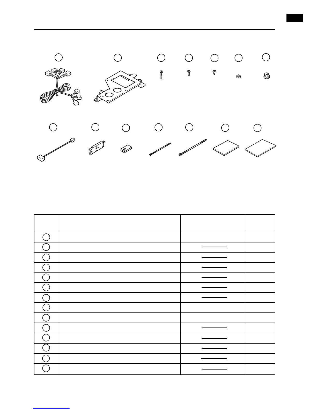
Contents List • Main Kit PZ409-F1275-00 / PZ409-F1276-00 ................ 36
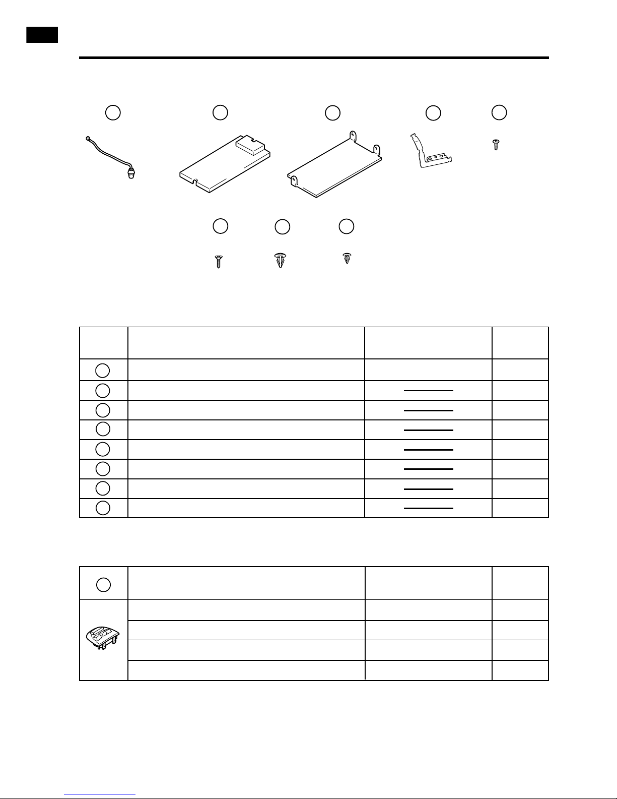
• Subkit 86075-50060 ........................................................ 37
• Switch case Charcoal 86174-50030-B0
Black 86174-50030-C0
Ivory 86174-50030-E0
Ecru 86174-50030-E1 ......................... 38
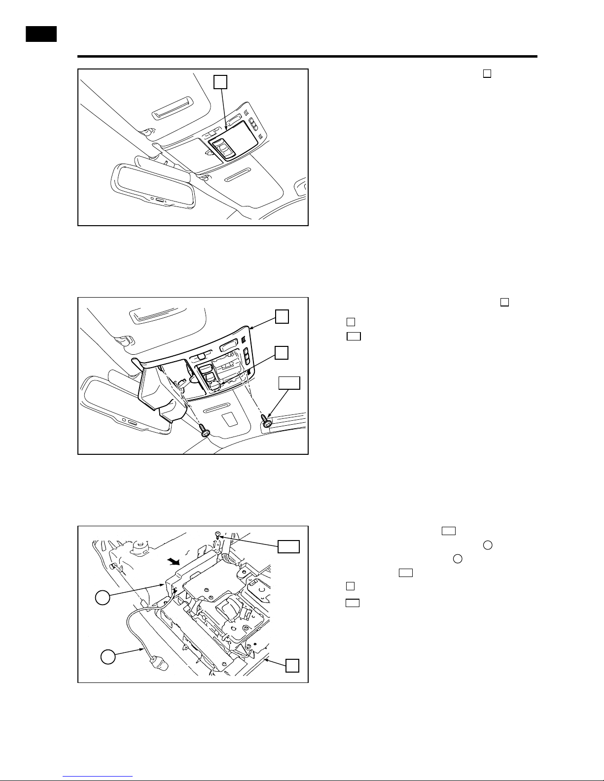
1. Command Module Installation ................................................................... 39
2. Microphone Installation .............................................................................. 40
3. Portable Phone Installation ........................................................................ 45
4. PSE Installation .......................................................................................... 50
5. Antenna Connection .................................................................................. 56
6. Steering Wheel Switch Mode Setting ........................................................ 57
7. Reassembly ............................................................................................... 58
8. Putting into Service .................................................................................... 58
LS 430
CMT - Dual band portable phone
33

LS 430
CMT - Dual band portable phone
34
Lexus Telephone System Overview
Microphone
Antenna
(Factory installed)
Steering wheel
command module
Cradle
Cradle conversion wire
Universal controller,
PSE + speaker relay
Subkit wire harness
Navigation ECU
(If equipped)
Antenna connector

LS 430
CMT - Dual band portable phone
35
Pre-Installation Instructions
1. Ensure the Radio Security Code is available and disconnect the negative
(-) lead from the battery terminals.
2. Protect Rear Right side fender and seats with covers.
3. When disconnecting connectors, be sure to grip the connector body. Do not
tug on the wiring.
4. If further information is required and for trouble shooting, please refer to the
Lexus Workshop Manual and the Electrical Wiring Diagram Manual EWD
435F.

LS 430
CMT - Dual band portable phone
36 Contents list MAIN KIT PZ409- F1274-00
No. Part Name Part No. Qty
Cradle 86722-0W050 1
Battery charger 86771-0W050 1
Handset pack 5 86770-0W080 1
pack 6 86770-0W090
Battery cover 86725-0W070 1
Rechargeable battery 86725-0W060 1
Speaker relay 86162-0W010 1
PSE (Portable Support Electronics) 86714-0W050 1
Universal controller PZ409-F1275-01 1
25P Subwire adapter cable 86713-0W110 1
Leather case 86778-0W030 1
Mainland Europe adapter plug 86771-0W060 1
UK adapter plug 86771-0W070 1
Ear Phone 86730-0W160 1
XII
XI
X
IX
VIII
VII
VI
V
IV
III
II
I
III III
VVI VII VIII
IX XXI XII
IV
F1275-00
F1276-00
[
[

LS 430
CMT - Dual band portable phone
37
Contents list SUBKIT 86075-50060
12367
8910 11 12 13 14
No. Part Name Part No. Qty
Subkit wire harness (Mobile phone wire) 86713-50100 1
Main bracket 1
Bolt (M4x12) 7
Bolt (M4x5) 4
Bolt (M4x12) 2
Nut (M4) 7
Nut (M6) 3
Cradle conversion wire 86773-50030 1
Microphone amplifier 86290-50010 1
Grommet 1
Wire tie (small) (L=142mm) 6
Wire tie (large) (L=190mm) 6
Foam (60x75) 10
Foam (60x85) 1
14
13
12
11
10
9
8
7
6
5
4
3
2
1
45

Command Module (SWITCH CASE) Part No. Qty
Charcoal 86174-50030-B0 1
Black 86174-50030-C0 1
Ivory 86174-50030-E0 1
Ecru 86174-50030-E1 1
23
LS 430
CMT - Dual band portable phone
38 Contents list SUBKIT 86075-50060 + SWITCH CASE
15 16 17
No. Part Name Part No. Qty
Microphone 86250-50010 1
Telephone tray 1
Partition plate 1
Cable support 1
Tapping screw (Ø4x9) 2
Flat head screw (Ø4.5x12) 4
Clip (large) 2
Clip (small) 1
22
21
20
19
18
17
16
15
18 19
20 21 22

LS 430
CMT - Dual band portable phone
39
1.1 Remove the command module cover
plate from the steering wheel as
shown.
: Hook (3x)
100
1
1.2 Fit the command module as shown.
Inspect to ensure that the module firm-
ly locks onto the steering wheel.
: Hook (3x)
100
23
1. COMMAND MODULE INSTALLATION
100
1
100
23
100

LS 430
CMT - Dual band portable phone
40
2.1 Remove the map light lens .
2
2.2 Remove the overhead module .
: Connector (1x)
: Screw (2x)
101
31
3
2.3 Remove the screw .
Connect the microphone on the
microphone amplifier after installing
one screw on the overhead module
.: Screw (1x)
107
3
107
9
15
107
2. MICROPHONE INSTALLATION
2
3
101
31
107
9
15
3

LS 430
CMT - Dual band portable phone
41
2.4 FOR LHD VEHICLE
Fit the microphone in the hole on the
overhead module as shown in the
illustration.
FOR RHD VEHICLE
Fit the microphone cord into the
hooks as shown in the illustration,
then insert the microphone into the
hole on the overhead module .
: Hook (2x)
103
3
15
103
24
3
15
2.5
a) Fit the microphone cord into the
hook as shown in the illustration,
then put the remainder into a crevice
so that it won’t be caught on the instal-
lation to the vehicle.
(The illustration is for LHD vehicle, but
it is also valid for RHD vehicle)
: Hook (2x)
b) Reinstall the overhead module to the
vehicle.
103
103
24
15
103
24
3
LHD VEHICLE
RHD VEHICLE
3
15
9
24
103

LS 430
CMT - Dual band portable phone
42
2.6 Open the centre console.
Remove the rear duct by gently lifting
upwards.
: Clip (2x)
104
4
2.7 Remove the control switch panel
from the vehicle as shown.
: Connector (1x)
: Clip (2x)
108
32
5
2.8 Remove the centre console shifter cov-
ers and .
: Connector (1x)
: Clip (4x)
108
40
7
6
104
4
108
32
5
7
108
40
6

LS 430
CMT - Dual band portable phone
43
2.9 Remove the centre console cup holder
.
: Screw (2x)
109
8
2.10 Disconnect the two 2P centre console
wire harness connectors .
9
2.11 Remove the bolts and screw from the
lower console box .
: Bolt (4x)
: Screw (1x)
109
105
10
109
8
9
109
105
10

LS 430
CMT - Dual band portable phone
44
2.12 Remove the console mat .
Remove the console box from the
vehicle as shown.
: Clip (2x)
: Bolt (2x)
105
102
10
11
2.13 Remove 26 screws on both sides
of the console box and on the stop-
per .
: Screw (26x)
110
12
10
110
2.14 Remove 4 bolts on the lower part
of the console box , then remove the
armrest .
: Bolt (4x)
111
13
10
111
105
11
10
102
110
Plate
Plate
110
12
10
111
10
13

LS 430
CMT - Dual band portable phone
45
3.1 Cut out the marked area in the illustra-
tion using the cutter.
: Console tray
14
3.2
a) Using the cutter, cut out the marked
area along the line on the rear part of
the lower console box for the tele-
phone wire to pass.
b) Drill a Ø5mm hole on the marked area
on the rear position of the lower con-
sole box .
10
10
3.3
a) Drill two Ø7mm holes on the marked
area on the front of the lower console
box .
b) Install the console tray in the lower
console box .
10
14
10
3. PORTABLE PHONE INSTALLATION
14
Cut out
Cut out
10
Cut here
Ø5mm hole
Ø7mm hole
10

LS 430
CMT - Dual band portable phone
46
3.5 Install the cradle on the telephone
tray using the M4x5 bolts .
: Bolt (M4x5) (4x)
4
4
16
I
3.6 Install the cable support for the tele-
phone wire on the back of the tray using
the tapping screws .
: Tapping screw (2x)
19
19
18
16
4
Wire harness
I
19
18
3.4
a) Punch the 2 holes in the telephone tray
and drill another 2 holes (Ø4mm) as
indicated in the drawing.
b) Cut away the cable hole.
16
Punch 2 holes
Drill 2 holes
16
30mm
26mm
30mm
26mm
Rib
Rib
Cable hole

LS 430
CMT - Dual band portable phone
47
3.9 Bundle up the antenna wire and cra-
dle conversion wire as shown in the
illustration using 3 wire ties .
: Wire tie (small) (3x)
11
11
8
I
3.8 Install the telephone tray in the con-
sole tray using 4 screws .
: Cradle conversion wire
: Flat head screw (4x)
: Cradle
I
20
8
20
14
16
See fig. 3.1
I
16
14
8
8
11
20
I
3.7
a) Connect the cradle conversion wire
and the telephone wire.
b) Route the telephone wire and the
antenna cord as shown in the illustra-
tion, then secure them using foam
and wire ties .
: Foam (small) (4x)
c) Secure the 18P connector using foam
for noise prevention on the area
shown in the illustration.
: Foam (large) (1x)
14
14
13
11
13
8
16
11
13
18P
14
8
Telephone wire

LS 430
CMT - Dual band portable phone
48
3.12
a) Locate the 18P vehicle connector at the
end of the centre console.
b) Remove the dummy connector .
c) Connect the cradle conversion wire
to the 18P vehicle connector.
d) Connect the antenna cord to the
vehicle connector (Mini UHF).
I
8
15
3.11 Reinstall the console box .
: Stopper (2x)
: Screw (26x)
110
12
10
110
Plate
Plate
110
10
12
15
18P
8
Mini UHF
Vehicle connector
I
3.10 Put the grommet around the tele-
phone wire, then pass it through the
hole.
The grommet should be installed
firmly in the hole.
10
10
see fig. 3.2
10
10
Don’t use this hole

LS 430
CMT - Dual band portable phone
49
3.13 Reinstall the console box .
: Bolt (2x)
105
10
3.14 Reinstall the bolts and screw
from the lower console box .
: Bolt (4x)
: Screw (1x)
109
105
10
109
105
3.15 Put the partition plate in the console
box as shown in the illustration, then
secure 3 positions using clips and .
When doing this, be careful not to catch
the telephone wire.
: Clip (large) (2x)
: Clip (small) (1x)
22
21
22
21
10
17
105
10
Connect the
connectors
105
109
10
10
17
21
22

LS 430
CMT - Dual band portable phone
50
4.1 Remove the luggage compartment car-
pet and floor board .
16
4.2 Remove the luggage compartment floor
boards (RH) .
: Clip (1x)
112
17
4.3 Remove the luggage compartment floor
boards (LH) .
: Clip (1x)
112
18
4. PSE INSTALLATION
16
17
112
18
112
Other manuals for Navigation System LS430
2
Table of contents