manuals.online logo
Brands
  1. Home
  2. •
  3. Brands
  4. •
  5. Lexus
  6. •
  7. Tuner
  8. •
  9. Lexus GX470 2007 User manual

Lexus GX470 2007 User manual

This manual suits for next models

2

Popular Tuner manuals by other brands

Technics ST-HD55 Service manual

Technics

Technics ST-HD55 Service manual

Arcam DT91 Handbook

Arcam

Arcam DT91 Handbook

HDHomeRun 20121008 installation instructions

HDHomeRun

HDHomeRun 20121008 installation instructions

Eico HFT-92 instruction manual

Eico

Eico HFT-92 instruction manual

MFJ MFJ-928 instruction manual

MFJ

MFJ MFJ-928 instruction manual

Teac T-1D Service manual

Teac

Teac T-1D Service manual

NAD C 445 owner's manual

NAD

NAD C 445 owner's manual

Sony ST-SA5ES operating instructions

Sony

Sony ST-SA5ES operating instructions

Pioneer GEX-P700DAB Operation manual

Pioneer

Pioneer GEX-P700DAB Operation manual

Sirius Satellite Radio SC-FM1 user guide

Sirius Satellite Radio

Sirius Satellite Radio SC-FM1 user guide

Antique Automobile Radio 283501B Installation and operating instructions

Antique Automobile Radio

Antique Automobile Radio 283501B Installation and operating instructions

Sanyo FMT M15L Service manual

Sanyo

Sanyo FMT M15L Service manual

Monacor PA-1200R instruction manual

Monacor

Monacor PA-1200R instruction manual

Technics ST-X301L Service manual

Technics

Technics ST-X301L Service manual

Manhattan 176156 user manual

Manhattan

Manhattan 176156 user manual

Marantz ST-15S1 user guide

Marantz

Marantz ST-15S1 user guide

Korg HA-40 owner's manual

Korg

Korg HA-40 owner's manual

Pioneer XC-IS21T Service manual

Pioneer

Pioneer XC-IS21T Service manual

manuals.online logo
manuals.online logoBrands
  • About & Mission
  • Contact us
  • Privacy Policy
  • Terms and Conditions

Copyright 2025 Manuals.Online. All Rights Reserved.

LEXUS GX470 2007 - XM SATELLITE RADIO TUNER
Preparation
Page 1 of 29 pages
Issue: D 11/18/08
Part Number: Tuner Assy 86180-0W030
Mounting Kit 86100-0W230
NOTE: Part number of this accessory may not be
the same as the part number shown.
Tuner Assy Kit Contents (86180-0W030)
Item # Quantity Reqd. Description
1 1
TUNER ASSY,
STEREO COMPONENT
Mounting Kit Contents (86100-0W230)
Item # Quantity Reqd. Description
1 1 Wire, To Radio Installation
2 1 Tuner Cover
3 1 Antenna
4 1 Grommet
5 1
Adhesive Sheet A (58mm185mm)
6 1
Adhesive Sheet B (26mm185mm)
7 3
Adhesive Sheet C (15mm182mm)
8 1
Adhesive Sheet D (17mm272mm)
9 1 Ground Cable
Hardware Bag Contents 1 (86100-0W230)
Item # Quantity Reqd. Description
1 14 Tie Wrap
2 6
Cushion Tape (50mm100mm)
3 1
Sheet (20mm80mm)
Hardware Bag Contents 2 (86100-0W230)
Item # Quantity Reqd. Description
1 1
Screw (M5L8 )
Hardware Bag Contents 3 (86100-0W230)
Item # Quantity Reqd. Description
1 1 Housing
2 1 Template
3 1 Cord Rail (10mm)
4 1 Cord Rail (20mm)
5 4
Nylon Tape (30mm30mm)
6㧝Cushion Tape (20mm100mm)
7 4 Tie Wrap
Additional Items Required For Installation
Item # Quantity Reqd. Description
Conflicts
iPod Interface, Sirius Satellite Radio
Recommended Tools
Personal & Vehicle
Protection
Notes
Vehicle Protection Clean Cloths, Part Boxes
Special Tools Notes
None
Installation Tools Notes
Panel Clip Removal Tool e.g. Toyota SST P/N:-
00002-06002-01
Socket 10mm, 14mm
Screwdriver Phillips, #2
Wrench Open End, 10mm, 14mm
Torque Wrench 4.1 N࡮M (36 lbf࡮in) (battery cable)
32 N࡮m (24 lbf࡮ft) (drivers seat)
42 N࡮m (31 lbf࡮ft) (rear seat belt)
37 N࡮m (27 lbf࡮ft) (third seat)
Scale
De-Burring Tool
Center Punch
Hole saw Ǿ7/8 inch
Side Cutter
Scissors
Masking tape
Special Chemicals Notes
None
General Applicability
Recommended Sequence of Application
Item # Accessory
*Mandatory
Vehicle Service Parts (may be required for reassembly)
Item # Quantity Reqd. Description
Legend
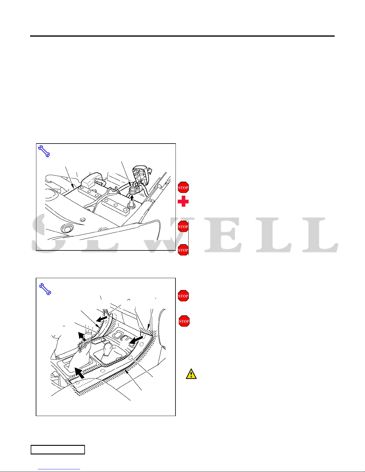
STOP: Damage to the vehicle may occur. Do not
proceed until process has been complied with.
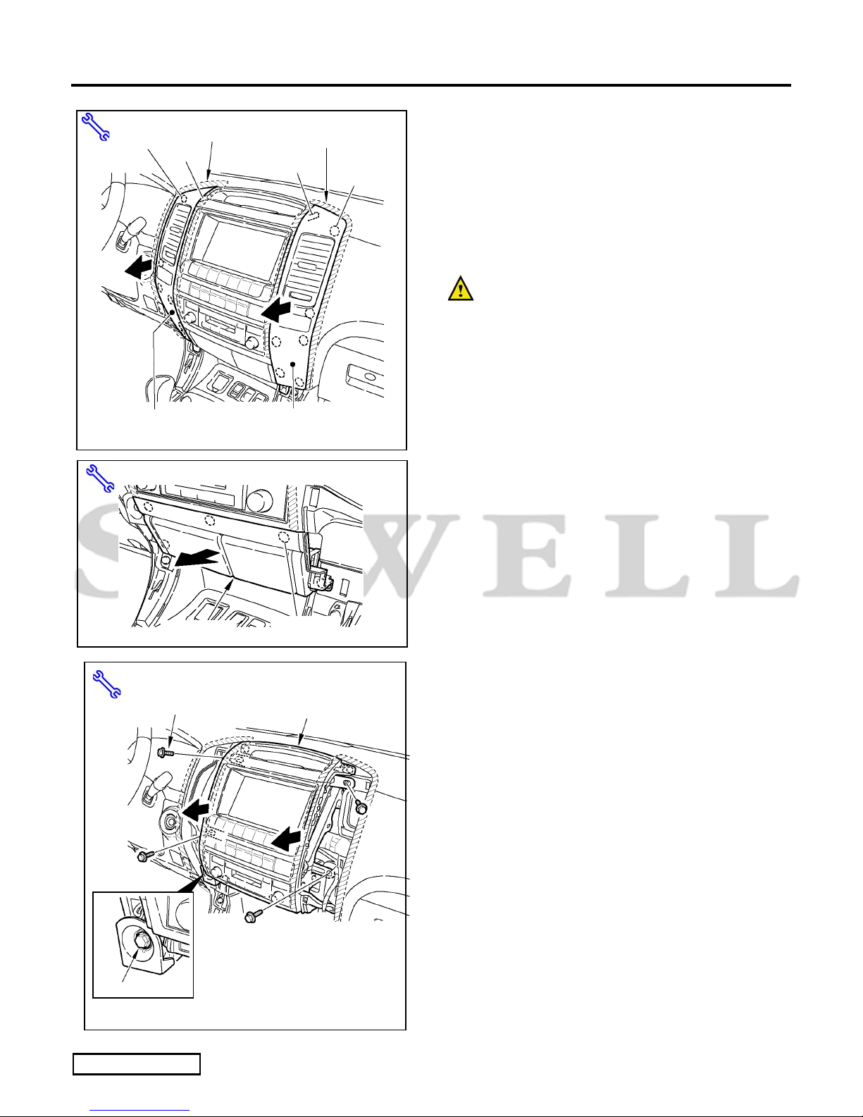
OPERATOR SAFETY: Use caution to avoid risk of
injury.
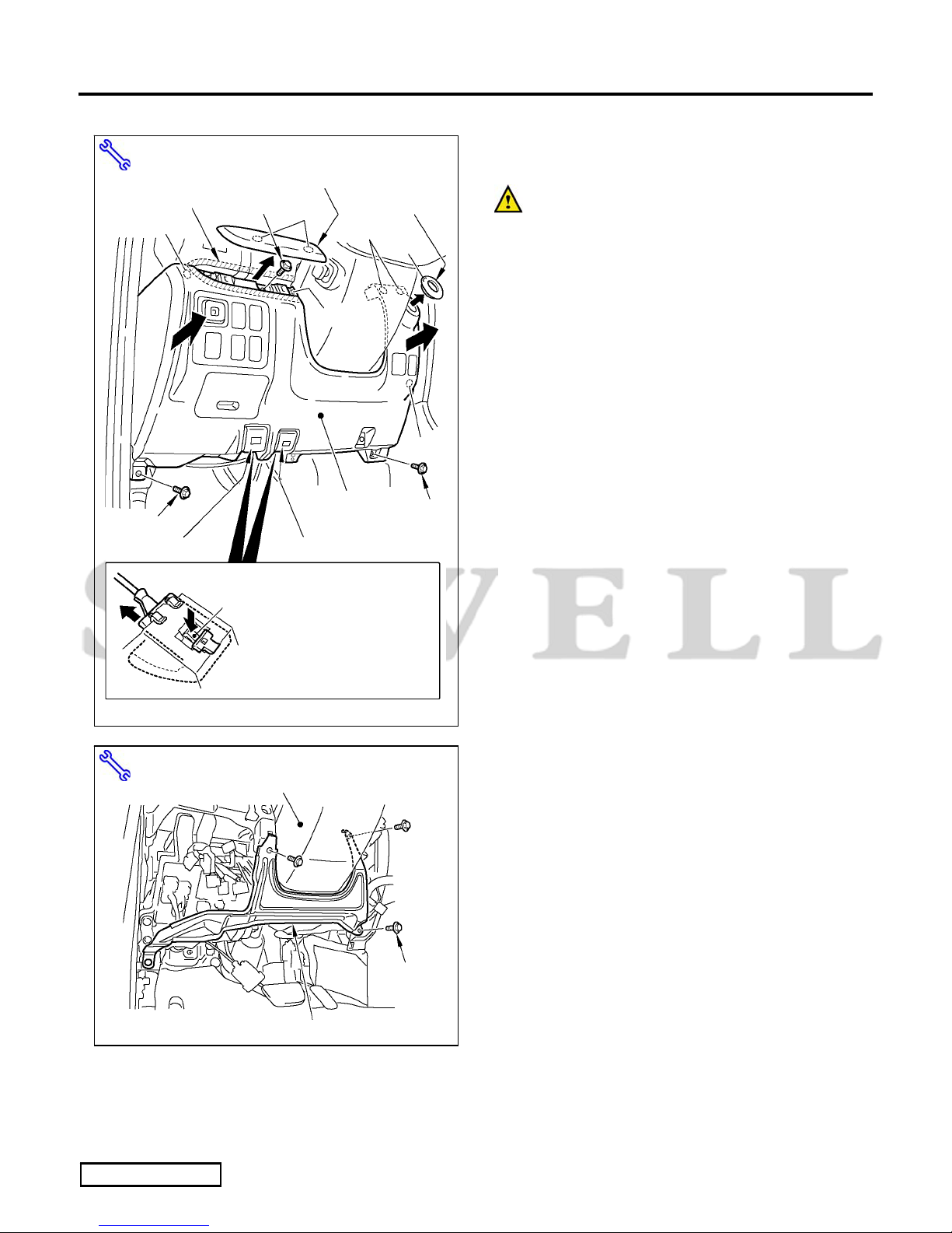
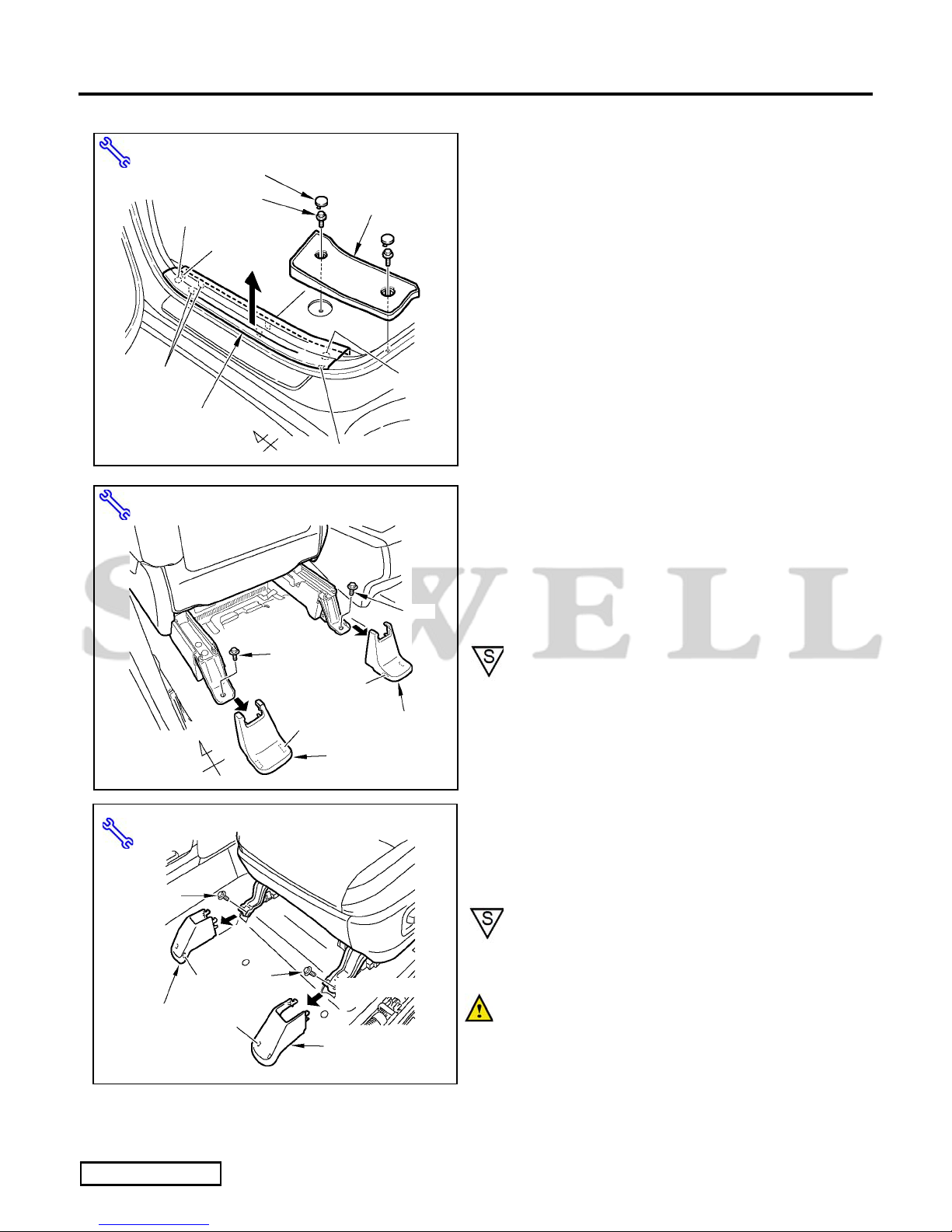
CAUTION: A process that must be carefully observed
in order to reduce the risk of damage to the
accessory/vehicle and to ensure a quality installation.
TOOLS & EQUIPMENT: Used in Figures calls out the
specific tools and equipment recommended for this
process.
REVISION MARK: This mark highlights a change in
installation with respect to previous issue.
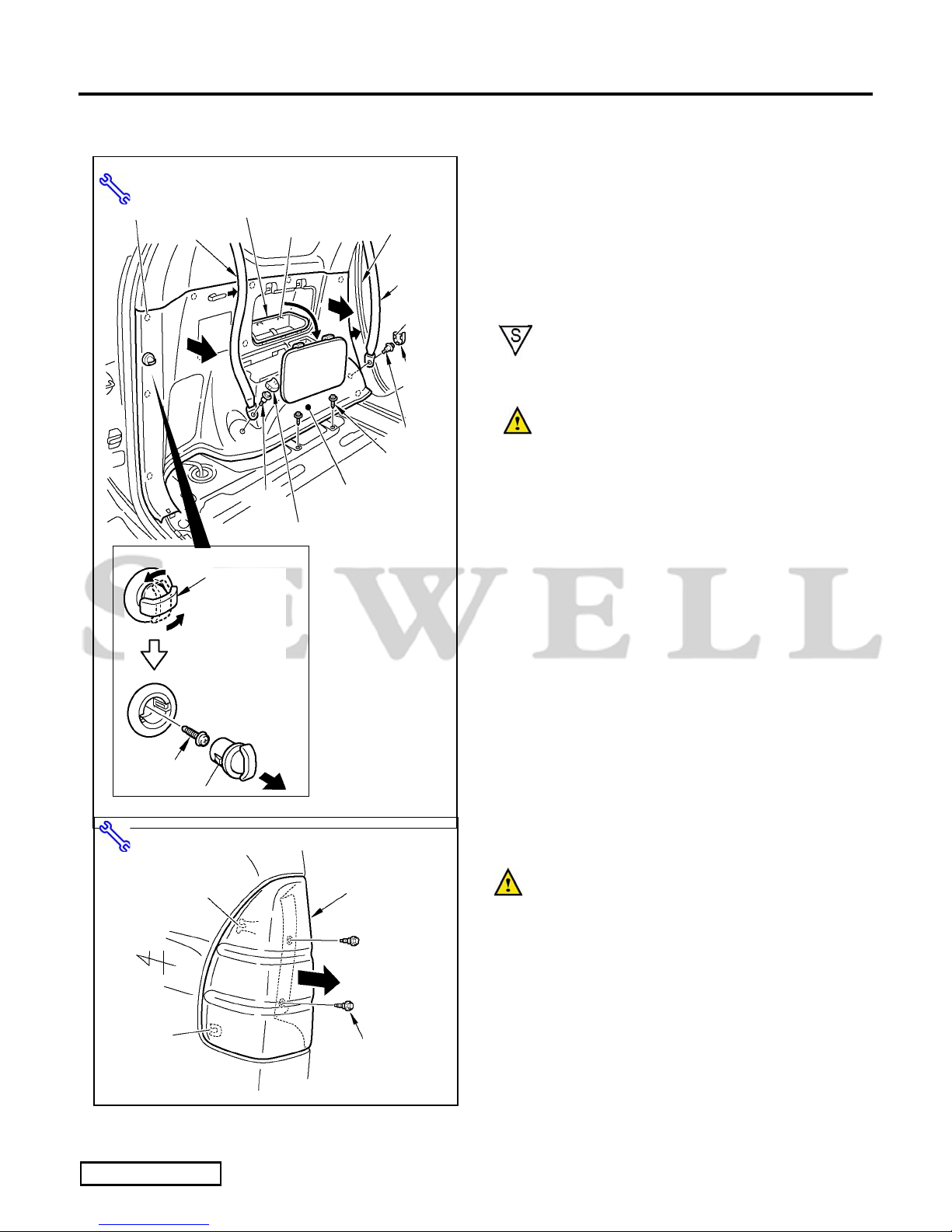
SAFETY TORQUE: This mark indicates that torque is
related to safety.
LEXUS GX470 2007 - XM SATELLITE RADIO TUNER
Preparation
Page 2 of 29 pages
Issue: D 11/18/08
Parts Description of Tuner Assy (86180-0W030)
Parts Description of Mounting Kit (86100-0W230)
1
ڎIn the installation instructions and figures, this is referred to as “Tuner”.
Item # Parts Name Parts No. Qty
1TUNER ASSY, STEREO COMPONENT ڎ86180-0W030 1
A
124 5
11
13
FH
B
6
8
ڎ㧝. In the installation instructions and figures, this is referred to as “Tuner Cable”.
ڎ㧞. One piece is used for the half cutting it (refer to Fig.4-4 & Fig.6-12).
Item # Parts Name Parts No. Qty
1Wire, To Radio Installation ڎ182372-0W110 1
2 Ground Cable 1
3 Tie Wrap 14
4Cushion Tape (50mm100mm) ڎ26
5Sheet (20mm80mm) 1
6 Grommet 1
7Adhesive Sheet A (58mm185mm) 1
8Adhesive Sheet B (26mm185mm) 1
9Adhesive Sheet C (15mm182mm) 3
10 Adhesive Sheet D (17mm272mm) 1
11 Screw (M5L8) 90153-50010 1
12 Tuner Cover 86215-0W180 1
A Antenna 1
B Housing 1
C Template 1
D Cord Rail A (10mm) 1
E Cord Rail B (20mm) 1
FNylon Tape (30mm30mm) 4
GCushion Tape (20mm100mm) 1
13
H Tie Wrap
86960-0W060
ANTENNA ASSY,
SATELLITE RADIO
4
3
D E G
7
910
C
12
LEXUS GX470 2007 - XM SATELLITE RADIO TUNER
Procedure
Page 3 of 30 pages
Issue: D 11/18/08
Care must be taken when installing this accessory to ensure damage does not occur to the vehicle. The installation of this
accessory should follow approved guidelines to ensure a quality installation.
These guidelines can be found in the "Accessory Installation Practices" document.
This document covers such items as:-
xVehicle Protection (use of covers and blankets, cleaning chemicals, etc.).
xSafety (eye protection, rechecking torque procedure, etc.).
xVehicle Disassembly/Reassembly (panel removal, part storage, etc.).
xElectrical Component Disassembly/Reassembly (battery disconnection, connector removal, etc.).
Please see your Lexus dealer for a copy of this document.
1. Vehicle Protection
(a) Place front driver seat in mid position.
(b) Set emergency hand brake.
(c) Remove the negative battery cable (Fig. 1-1).
(1) Protect the fender before starting.
(2) Do not touch the positive terminal with
any tool when removing cable.
(d) Using protective blankets cover front and
middle seats, interior of vehicle, and center
console forward of shifter.
(e) Wait 90 seconds before proceeding to
disassemble vehicle.
2. Disassembly of Vehicle
NOTE: Place all removed parts on a protected
surface.
NOTE: When disconnecting wiring connectors,
do not pull on the wiring; pull on the connector
only.
(a) Remove the console side cluster (L,R)
(Fig. 2-1).
(1) Affix masking tape around the edge of
the cluster (the shaded area) to protect the
unit from damage.
(2) Pull the cluster in the sequence of Ԙψ
ԙas shown in the illustration to remove
the clips and claw.
Fig. 1-1
Wrench, 10mm Socket
N
egative Battery Cable
Battery
Fig. 2-1
ԙ
Ԙ
ԙ
Ԙ
Masking Tape
Masking Tape, Panel Removal Tool
Clips (3)
Console Side
Cluster (L)
Claws
Masking Tape
Clips (4)
Console Side
Cluster (R)
LEXUS GX470 2007 - XM SATELLITE RADIO TUNER
Procedure
Page 4 of 30 pages
Issue: D 11/18/08
(b) Remove the Instrument Panel Cluster (L,R)
(Fig. 2-2).
NOTE: The illustration shows a vehicle
equipped with EMV, but the procedure is the
same for standard audio.
(1) Affix masking tape around the edge of
the cluster (the shaded area) to protect the
unit from damage.
(2) Pull the cluster in the arrowed directions,
then detach the clips and claws.
(3) Disconnect the wiring connector.
(c) Remove the cigarette box (Fig. 2-3).
NOTE The illustration shows a vehicle equipped
with EMV, but the procedure is the same for
standard audio.
(1) Pull the box in the direction of the arrow,
and remove the clips.
(2) Disconnect the wiring connector.
(d) Remove the audio assembly (Fig. 2-4).
NOTE: The illustration shows a vehicle
equipped with EMV, but the procedure is the
same for standard audio.
(1) Remove the mounting bolts.
(2) Loosen the harness connector’s coupling
bolt.
(3) Pull the audio assembly in the direction
of the arrow, and disconnect the wiring
connector.
Fig. 2-2
Masking Tape
Clips (6)
Instrument Panel
Cluster (R)
Masking Tape, Panel Removal Tool
Masking Tape
Claw
Claw
Clips (6)
Instrument Panel Cluster (L)
Panel Removal Tool
Clips (5)
Cigarette Box
Fig. 2-3
Audio assembly
Bolts (4)
Fig. 2-4
Wrench, 10mm Socket
Coupling bolt
LEXUS GX470 2007 - XM SATELLITE RADIO TUNER
Procedure
Page 5 of 30 pages
Issue: D 11/18/08
(e) Remove the front scuff plate (L) (Fig. 2-5).
(1) Pull the plate in the sequence of Ԙψ Ԛ
as shown in the illustration to remove the
clips and claws.
(f) Remove the footrest (Fig. 2-6).
(1) Pull the footrest in the direction of the
arrow to remove it.
(g) Remove the cowl side cover (L) (Fig. 2-6).
(1) Remove the Nut.
(2) Pull the cover in the direction of the
arrow, and remove the clips.
(h) Remove the instrument panel under cover (L)
(Fig. 2-7).
(1) Remove the screw.
(2) Pull the cover in the direction of the
arrow, and remove the clip and claw.
(3) Disconnect the wiring connector.
Panel Removal Tool
Fig. 2-5
Claw
Front Scuff Plate (L)
Claws (4)
Clip
Claw
(slide it towards the
front to remove)
Front
ԙ
Ԙ
Ԛ
Panel Removal Tool
Cowl Side Cover (L)
Clips (2)
Fig. 2-6
Footrest
N
ut
Clips (2)
Floor Bolts (2)
Fig. 2-7
Phillips Screwdriver, Panel Removal Tool
Clip
Screw
Instrument Panel Under Cover (L)
Clip
Claw
LEXUS GX470 2007 - XM SATELLITE RADIO TUNER
Procedure
Page 6 of 30 pages
Issue: D 11/18/08
(i) Remove the instrument panel lower cover (L)
(Fig. 2-8).
(1) Affix masking tape around the edge of
the instrument panel cluster molding (L)
(the shaded area) to protect the unit from
damage.
(2) Remove the instrument panel cluster
molding (L), then remove the Bolt.
(3) Remove the bolts from the under side.
(4) Remove the key cylinder cover.
(5) Pull the cover in the direction of the
arrow, and remove the clip and claw.
(6) Remove the hood opener.
(7) Remove the fuel lid opener.
(8) Disconnect the wiring connector.
(j) Remove the harness guard bracket at the
bottom of the steering column (Fig. 2-9).
(1) Remove the mounting bolts.
Masking Tape, Panel Removal Tool, Wrench
10mm Socket
Fig. 2-8
Clips
Claw
Instrument Panel Cluster Molding (L)
Fuel Lid Opener
Clip
Bolt
Clips
Key Cylinder
Cover
Claw
Bolt
Bolt
Instrument Panel
Lower Cover (L)
Clip
Press down on the lock at the
top from inside and then slide it
towards the front to remove it.
(The illustration shows the fuel
lid opener, but the hood opener
is the same.)
Hood Opener
Lock
Masking Tape
Wrench, 10mm Socket
Harness Guard Bracket
Fig. 2-9
Steering Column
Bolts (3)
LEXUS GX470 2007 - XM SATELLITE RADIO TUNER
Procedure
Page 7 of 30 pages
Issue: D 11/18/08
(k) Remove the rear step cover (L) (Fig. 2-10).
(1) Remove the caps, then remove the bolts.
(l) Remove the rear scuff plate (L) (Fig. 2-10).
(1) Pull the plate in the direction of the arrow,
and remove the clip and claw.
(m) Remove the driver’s seat.
(1) Remove the seat leg covers on the rear
side (Fig. 2-11).
(2) Remove the rear mounting bolts (Fig. 2-
11).
NOTE: When putting the mounting bolts back,
tighten them to 32.0 N㨯m (24 lbf㨯ft).
(3) Remove the seat leg covers on the front
side (Fig. 2-12)
(4) Remove the front mounting bolts (Fig. 2-
12)
NOTE: When putting the mounting bolts back,
tighten them to 32.0 N㨯m (24 lbf㨯ft).
NOTE: Place a protective cloth over metal
seat legs to prevent vehicle component
damage
Panel Removal Tool, Wrench, 14mm Socket
Fig. 2-11
Bolt
Leg Cover (L)
Driver’s Seat
Claws (2)
Front Claws (2) Leg Cover (R)
Bolt
Panel Removal Tool, Wrench, 10mm Socket
Fig. 2-10
Bolts (2) Rear Step Cover (L)
Caps (2)
Rear Scuff Plate (L)
Claws (2)
Claw
Clip
Claw
Clip
Front
Panel Removal Tool, Wrench, 14mm Socket
Fig. 2-12
Leg Cover (L)
Claws
(2)
Le
g
Cover
(
R
)
Bolt
Driver’s Seat
Claws
(2)
Bolt
LEXUS GX470 2007 - XM SATELLITE RADIO TUNER
Procedure
Page 8 of 30 pages
Issue: D 11/18/08
(5) Tilt seat back. Do not remove the seat.
NOTE: Ensure there is enough slack in wire
harness when the seat is tilted back.
(6) If enough slack is not obtained, Push the
seat over towards the rear and remove the
seat harness connectors and clamp (Fig.
2-13).
(n) Remove the third seat (L).
(1) Remove the seat hinge cover (Fig. 2-14).
(2) Lower the hinge lock lever to the left (Fig.
2-14).
(3) Pull the lock wire lever and then lift the
third seat in the direction of the arrow to
remove it (Fig. 2-15).
Fig. 2-13
Connectors
Front
Panel Removal Tool
Clamp
Seat Harness
ާThe seat as seen from belowި
Panel Removal Tool
Fig. 2-14
Seat Hinge Cover Clips (2)
Front
Third Seat (L)
Hinge Lock Lever
(Lower it to the left)
Claws (2)
Fig. 2-15 Lock Wire Lever
Third Seat (L)
LEXUS GX470 2007 - XM SATELLITE RADIO TUNER
Procedure
Page 9 of 30 pages
Issue: D 11/18/08
(4) Remove the seat hinge (Fig. 2-16).
NOTE : When putting the mounting bolts
back, tighten them to 37.0 N㨯m (27 lbf㨯ft).
(o) Remove the luggage finish plate (Fig. 2-17).
(1) Remove the cap, then remove the screws.
(2) Pull the plate in the direction of the arrow,
and remove the clip and claw.
(p) Pull back the luggage carpet (Fig. 2-18).
(1) Loosen the bolt and remove the front
rope hook.
(2) Loosen the bolt and remove the rear rope
hook.
(3) Pull back the carpet in the direction of the
arrow.
Panel Removal Tool, Wrench, 14mm Socket
Fig. 2-16
Seat Hinge
Bolts (2)
Open the caps.
Panel Removal Tool, Phillips Screwdriver
Fig. 2-17
Clip
Luggage Finish Plate
Front
Claws (2)
Clip
Claws (2)
Caps (5)
Screws (5)
Panel Removal Tool, Wrench, 10mm Socket
Fig. 2-18
Cap
Luggage Carpet
Front
Rope Hook (Front)
Open the cap and loosen the bolt.
Rope Hook (Rear)
LEXUS GX470 2007 - XM SATELLITE RADIO TUNER
Procedure
Page 10 of 30 pages
Issue: D 11/18/08
(q) Fold and rotate driver side second row seat
forward to access rear quarter panel trim.
(r) Remove the luggage side lower trim (L) (Fig.
2-19).
(1) Remove the cover, then remove the
accessory box.
(2) Remove the two (2) seat belts.
NOTE : When putting the mounting
bolts back, tighten them to 42.0 N㨯m (31
lbf㨯ft).
NOTE: Cover the seat belt anchor and
bolts with masking tape.
(3) Remove the rope hook, then remove the
screw.
(4) Remove the floor screw.
(5) Pull back the front weather strip.
(6) Pull the trim in the direction of the arrow,
and remove the clip and claw.
(s) Remove the rear combination lamp (L) (Fig.
2-20).
NOTE: Cover the perimeter of the tail
lamp assembly prior to removal.
(1) Remove the bolts.
(2) Pull the lamp in the direction of the arrow,
and remove the claws.
(3) Disconnect the wiring connector.
Cover
Panel Removal Tool, Wrench, 14mm Socket
Phillips Screwdriver
Fig. 2-19
Accessory Box
Bolt
Seat Belt Claws (5) Weather Strip
Seat Belt
Claws (2)
Cover
Cover (Claws2)
Screws (2)
Bolt Luggage Side
Lower Trim (L)
Rope Hook
Turn the rope hook
90 degrees and remove
when it is vertical.
Screw
Claws (2)
Clips (9)
Panel Removal Tool, Wrench, 10mm Socket
Fig. 2-20
Bolts (2)
Front
Claw
Rear Combination
Lamp (L)
Claw