LEYBOLD SCROLLVAC plus User manual

SCROLLVAC plus
Minor Service Manual
Tip Seal and Exhaust Valve Replacement
Operating Instructions 300680362_002_C0
Spare Part Kit Numbers
EK117141000 Minor Service Kit SC 7-15
EK117141001 Minor Service Kit SC 18
EK117141002 Minor Service Kit SC 7-15 C
EK117141003 Minor Service Kit SC 18 C
for Pump Part Numbers
1410xxVxx
1411xxAxx

Contents
2 300668736_002_C0 - 11/2017 - © Leybold
Page
Original operating instructions.
0 Important safety information 4
0.1 Mechanical hazards 4
0.2 Electrical hazards 4
0.3 Thermal hazards 4
0.4 Hazards caused by materials and substances 4
1 Replace the tip seals 5
2 Exhaust valve and gas ballast valve replacement 10

Safety Information
3300668736_002_C0 - 11/2017 - © Leybold
Obligation to Provide Information
Before installing and commissioning the pump, carefully read these
Operating Instructions and follow the information so as to ensure optimum
and safe working right from the start.
The Leybold SCROLLVAC plus has been designed for safe and efficient
operation when used properly and in accordance with these Operating
Instructions. It is the responsibility of the user to carefully read and strictly
observe all safety precautions described in this section and throughout the
Operating Instructions. Moreover, observe the information in all additionally
supplied Operating Instructions for switches or valves, for example.The pump
must only be operated in the proper condition and under the conditions
described in the Operating Instructions. It must be operated and maintained
by trained personnel only. Consult local, state, and national agencies regard-
ing specific requirements and regulations. Address any further safety, opera-
tion and/or maintenance questions to our nearest office.
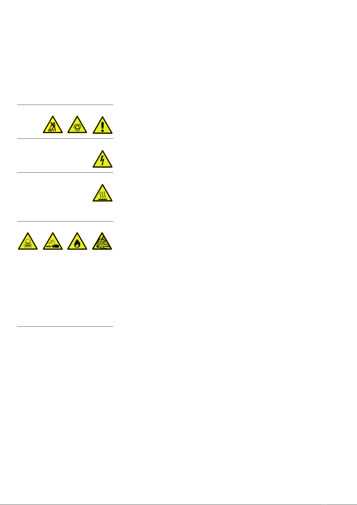
DANGER indicates an imminently hazardous situation which, if not avoid-
ed, will result in death or serious injury.
WARNING indicates a potentially hazardous situation which, if not
avoided, could result in death or serious injury.
CAUTION indicates a potentially hazardous situation which, if not avoided,
could result in minor or moderate injury.
NOTICE is used to notify users of installation, operation, programming or
maintenance information that is important, but not hazard related.
We reserve the right to alter the design or any data given in these Operating
Instructions. The illustrations are not binding.
Retain the Operating Instructions for further use.
NOTICE
DANGER
WARNING
CAUTION
NOTICE

Safety Information
4 300668736_002_C0 - 11/2017 - © Leybold
0 Important safety information
0.1 Mechanical hazards
1 Heavy object. Risk of physical injury. Use suitable lifting equipment.
0.2 Electrical hazards
1 Do not operate the pump with any parts of the enclosures removed or
damaged as there may be a risk of an electric shock.
0.3 Thermal hazards
1 Risk of burns. Do not touch the pump inlet or exhaust ports whilst the
pump is running since the temperatures of these parts could be high
enough to cause harm. Elevated temperatures could remain after the
pump has stopped.
0.4 Hazards caused by materials and substances
1 If within the system toxic substances or gases are being used, then
the operator will be responsible for ensuring that the corresponding
safety precautions are introduced!
2 If the pump has previously pumped hazardous gases take the appro-
priate safety measures before opening the intake or exhaust ports.
Use gloves, a breathing mask or protective clothing to avoid skin con-
tact with toxic or highly corrosive substances. Work under a fume
hood.
3 Contaminated parts can be detrimental to health and environment.
Before beginning with any work, first find out whether any parts are
contaminated. Adhere to the relevant regulations and take the neces-
sary precautions when handling contaminated parts.
WARNING
DANGER
CAUTION
DANGER

5300668736_002_C0 - 11/2017 - © Leybold
1 Replace the tip seals
Replace the tip seal as described below. Prepare the pump by running on
gas ballast control for one hour to remove any process gases.
1. Switch off the pump and isolate from the electrical supply.
2. Using a 4 mm Allen key, undo the two screws (Figure 1, item 1) which
secure the fan cowl and remove.
3. Disconnect the motor fan lead from the controller (figure 2, item 1).
Figure 2 - Motor fan lead connector
1
Figure 1 - Fan cowl removal
1

6 300668736_002_C0 - 11/2017 - © Leybold
4. Using a 4 mm Allen key, undo the four screws (Figure 3, item 1) which
secure the fixed scroll assembly to the housing assembly.
5. Carefully separate the fixed scroll assembly from the housing assembly
using a suitable lever in the slots provided (Figure 4).
Figure 4 - Pump side views
Levering slot
Figure 3 - Remove the fixed scroll assembly
1

7300668736_002_C0 - 11/2017 - © Leybold
6. Starting from one end, remove the tip seal from the fixed scroll. Repeat
this operation for the orbiting scroll (Figure 5, item 3). Remove the fixed
scroll O-ring (Figure 5, item 4). Dispose of all used items that have been
removed following this operation.
Note: Avoid damaging the fixed scroll O-ring groove when removing the
O-ring.
7. Using a clean dry lint-free cloth and IPA, remove all dust and process
debris from the scroll forms and grooves. Heavier process debris can be
removed with Green Scotch Brite®only.
8. Taking a new tip seal, fit it using the following technique in both the orbit-
ing scroll and the fixed scroll:
Figure 5 - Replacing the tip seals
1 Housing assembly
2 Orbiting scroll
3 Tip seal
4 Fixed scroll O-ring
5 Fixed scroll
6 Fixed scroll fixing screws
7 Fan-cowl
8 Alignment dowel
13 4 3 5 6 7
8
2

8 300668736_002_C0 - 11/2017 - © Leybold
Starting at the centre of the scroll form, insert the tip seal into the tip seal
channel. Ensure that each tip seal starts as close as possible at the start of
the scroll channel. (Figure 6).
Note: The SCROLLVAC 18 plus has multiple tip seal starts in both the
Orbiting and Fixed scrolls.
Continue to push the tip seal into the tip seal channel while working your way
around the channel profile until you have reached the end. Ensure the tip seal
is pressed squarely and fully home at each pinch point, these are located
closer to the centre of the scroll.
Cut short the tip seal at the end of the scroll channel. There should be at
least 10 mm between the end of the channel and the tip seal, this is to allow
for expansion.
Note: A mark is provided at the end of all the tip seal channels to indicate
where to cut the tip seal (Figure 7).
Figure 6 - Tip seal fitting
SCROLLVAC SC 7 to SC 15 plus SCROLLVAC SC 18 plus

9300668736_002_C0 - 11/2017 - © Leybold
Remove any tip seal debris which may have been produced while inserting
the new tip seals.
9. Fit the new O-ring (Figure 5, item 4) onto the fixed scroll (Figure 5, item
5). The O-ring may be moistened with water (H2O) only, to aid assembly.
10. Assemble the fixed scroll assembly up to the housing assembly (figure 5,
item 1). Be careful and do not damage the O-ring. Check that the align-
ment dowel (Figure 5, item 8) in the housing assembly lines up with the
hole in the fixed scroll. Ensure that the fixed scroll is fitted squarely onto
the housing assembly.
11. Tighten the fastening screws (Figure 5, item 6) in small increments using
a 4 mm Allen key and pull-up evenly the fixed scroll assembly onto the
housing assembly. Torque each screw to 9 Nm. Do not start by assem-
bling one side first.
Note: Do not to damage or trap the O-ring (figure 5, item 4).
12. Reconnect the fan-cowl as described on page 11 (unless you want to
replace valves in addition).
13. When operating your pump following a tip seal change, ensure the fan is
operating correctly.
Note: The pump tip seals may take a few hours to bed-in before full perfor-
mance is restored.
Figure 7 - Tip seal finish mark
1 Tip seal
2 Cut mark
3 Gap (approximately 10 mm)

10 300668736_002_C0 - 11/2017 - © Leybold
2 Exhaust valve and gas ballast valve replacement
Prepare the pump and disconnect the fan cowl as shown on page 5.
Exhaust valve(s)
1. Using an adjustable pin spanner remove the exhaust valve – pad –
spring - O-ring assembly (Figure 8, item 1)
2. Dispose of all used items that have been removed following this opera-
tion: spring, pad and O-ring (figure 9, items 1, 2 and 3) and replace with
new items.
3. Ensure all surfaces are clean before assembling the exhaust valve
assembly including O-ring.
Note: Do not to damage or trap the O-ring (figure 9, item 3). Do not use any
oil or lubricant during the assembly
4. Assemble to the top of the fixed scroll using an adjustable pin spanner.
Torque each screw to 6 Nm. If no torque tool is available closest to the
exact torque is acceptable.
Gas ballast valve
5. Using a 22 mm AF spanner (Figure 8, item 2) or adjustable pin spanner
(figure 8, item 3) remove the control knob - gas ballast nut – shaft –
spring - O-ring assembly (figure 10).
Figure 8 - Remove the valve assemblies
SCROLLVAC SC 7 to SC 15 plus
Standard and C-Versions
12
SCROLLVAC SC 7 to SC 15 plus
H-Versions
13
SCROLLVAC SC 18 plus
Standard and C-Versions
12
1 Exhaust valve – pad – spring – O-ring assembly
2 Gas ballast control knob – shaft – spring – O-ring assembly
3 Gas ballast nut – shaft – spring – O-ring assembly

11300668736_002_C0 - 11/2017 - © Leybold
Figure 9 – Exhaust valve assembly Figure 10 – Gas ballast knob and valve assembly
1 Pad
2 Spring
3 O-Ring 1
2
3
4
5
1 Gas ballast valve seat
2 O-ring
3 O-ring
4 Pad
5 Spring
6. Remove the gas ballast valve seat (figure 10, items 1) from spring, valve
pad and O-rings (figure 10, items 2, 3, 4 and 5).
7. Dispose of all used items that have been removed following this opera-
tion: spring, pad and O-rings (figure 10, items 2, 3, 4 and 5) and replace
with new items.
8. Ensure all surfaces are clean before assembling the gas ballast valve
assembly including O-ring.
9. Assemble the gas ballast assembly valve components back.
Note: Do not to damage or trap the O-ring (figure 10, item 2 and 3). Do not
use any oil or lubricant during the assembly
10. Assemble knob and exhaust valve assembly to the side of the fixed
scroll using a 22 mm AF spanner (Figure 8, item 2) or adjustable pin
spanner (figure 8, item 3). Torque each screw to 6 Nm. If no torque tool
is available closest to the exact torque is acceptable.
Reconnect the fan-cowl
11. Connect the motor fan lead into the mating connector at the controller
(figure 2, item 1).
12. Assemble the fan-cowl assembly onto the housing assembly by hand
using even downward pressure.
13. Tighten the fastening screws in small increments.
14. Reinstall your pump in accordance with Section 3 of the SCROLLVAC
plus manual.
15. When operating your pump following a valve replacement, ensure the
fan is operating correctly.

Leybold GmbH
Bonner Str. 498 · D-50968 Köln
T +49 (0) 221-347-0
F +49 (0) 221-347-1250
www.leybold.com
Leybold Services.
Worldwide available.
We are continuously expanding our service network.
The current contact details can be obtained on our website.
Your contact – wherever you are:
www.leybold.com
LV_20396_2017 11.17
Table of contents
Other LEYBOLD Control Unit manuals