manuals.online logo
Brands
  1. Home
  2. •
  3. Brands
  4. •
  5. LF Engineering
  6. •
  7. Antenna
  8. •
  9. LF Engineering L-400B User manual

LF Engineering L-400B User manual

L-400B LF Active Gain Antenna
The L-400B active gain antenna is a compact 26
inch antenna designed specifically for the VLF
and LF spectrum. The L-400B may be used with
all receivers and converters.
The L-400B broadband design enables you to
effectively receive the whole LF spectrum from 10
kHz through 500 kHz without the need of a tuner.
The L-400B has very high E field sensitivity with
the advantage of excellent BC intermodulation
rejection with its sharp roll off filter.
A proprietary gain amplifier and low pass filter
makes the L-400B a compact and
totally sealed probe (no whip). The
antenna is omni directional allowing
for various installation
configurations and for use as a
portable antenna. The L-400B
probe is waterproof and UV
resistant.
Features
10kHz to 500 kHz
broadband coverage
(no tuner required)
50 ft of RG174/U
with RCA connector
included.
No BC intermod can
be detected even 1/4
mile from a 5 kW
broadcast station
The antenna probe
is fully sealed and
does not use a whip
antenna
Extended ESD and
RF protection
Mounting clamp
included
Dual source power
design: Internal 9
volt battery (x2) or
external 120 vac /
12 vdc supply
(included)
L-400B Specifications
Antenna Probe Size 26 inches long, 1 inch dia.
Coupler Size 4.19"L x 2.74"W x 1.57"H
Filter Rejection >40 dB above 600 kHz
E Field Sensitivity -3 dB @ 250 kHz
Low Pass Filter Response 10 kHz to 500 kHz
IP3 24 dBm
Internal (E probe) Amplifier Gain 20 dB
Input/Output Jacks RCA
Operating Temperature -250F to +1200F
Weatherproofing Antenna probe tested to -2 atmospheres (-66 ft)
DC Power: 12 - 18 Volt, 20 ma, NEDA (2) or equivalent battery
AC Power: (included) 120 vac / 12 vdc power pack with 2.5 mm plug
L-400B LF Active Gain Antenna
Copyright LF Engineering Co.
All rights reserved.
Printed in U.S.A.
LF Engineering Co.
17 Jeffry Road
East Haven, CT 06513
Product Warranty
LF Engineering Co. warrants that, at the time of shipment the products
manufactured by LF Engineering Co. are free from defects in material
and workmanship. LF Engineering Co. obligation under this warranty is
limited to replacement or repair of such products within 1 year from the
date of shipment.
For sales or return authorization,
contact LF Engineering Co. at (860) 526-4759.
LF Engineering E-mail address: [email protected]
Introduction:
The L-400B Active Antenna covers the full low frequency spectrum from
10 kHz through 500 kHz. A proprietary low pass filter is used to prevent
AM broadcast inter-modulation and a proprietary low noise 20 dB gain
amplifier (2 wire feed) insures ample gain throughout the spectrum. The
output impedance of the L-400B is 50 to 100 ohms, and is designed to
match most receivers and converters in use today. The Receiver Coupler
requires two 9 volt batteries (18v) for operation. An external 120 vac / 12
vdc power supply is included for continuous operation.
Battery Installation:
Remove the 4 Philip head screws from the four corners of the front panel.
Lift the panel/circuit board from the
cabinet and install two 9 volt batteries
onto the two battery clips.
Reassemble panel into cabinet. The
battery life with normal intermittent
operation is more than 4 months.
AC Power Supply:
The 120 vac / 12 vdc power supply plugs into the
2.5 mm jack located on the front panel. The ac
power supply may be used even with a battery
internally connected. The 2.5 mm plug disables the
internal battery when inserted into the panel jack.
Installation:
1. Mount the antenna E probe in the clear 8 ft to 20 ft high in the clear,
preferably roof height. Use the stainless clamp supplied for attachment
to a vertical support pole.
a. A support pole may be any vertical structure made from wood,
metal or PVC that is between 1 and 2 inches in diameter. You may
use an external roof structure such as the top of a TV mast or roof
vent pipe. Note: The use of a vent pipe or any other large diameter
mounting surfaces will require a larger mounting clamp.
b. The support pipe should not be attached any higher than the
neoprene grip as shown in the illustration.
2. Connect the coupler output (RCVR) to the antenna input terminals of
your short-wave receiver with input impedance between 50 and 100
ohms.
3. Route the antenna cable to your receiver. Longer lengths of cable
may be added . Connect the antenna cable to the coupler (ANT) input.
a. Coax length may be extended 150 ft for a total of 200 ft max.
length.
4. Turn the coupler on and your receiver on. The coupler LED will light
and your system is now ready for use.
How to Get the Most Out Of Your L-400B Active Gain Antenna:
1. Keep your antenna in the clear and above metal objects (8 ft
minimum height) and use a good ground on your receiver.
2. When mounting onto a metal pole, mounting area should not exceed
the neoprene grip.
3. Use a cable strain relief (clamp, strap, tape) around the mounting
pipe and cable to reduce cable fatigue at the antenna.
4. Mount your antenna away from man
made EMI such TV sets, light
dimmers and other noise generators.

Other LF Engineering Antenna manuals

LF Engineering L-950 User manual

LF Engineering

LF Engineering L-950 User manual

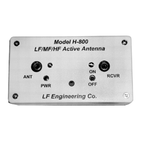
LF Engineering H-800 SKYMATCH User manual

LF Engineering

LF Engineering H-800 SKYMATCH User manual

Popular Antenna manuals by other brands

Meinberg GPSANT manual

Meinberg

Meinberg GPSANT manual

Philex 27881D4 user guide

Philex

Philex 27881D4 user guide

M2 2M HO LOOP Assembly manual

M2

M2 2M HO LOOP Assembly manual

Lectrosonics UMC16B instruction manual

Lectrosonics

Lectrosonics UMC16B instruction manual

Opus C-900 Installation and user manual

Opus

Opus C-900 Installation and user manual

GOMOHU LEAF 30 instruction manual

GOMOHU

GOMOHU LEAF 30 instruction manual

Siemens SIMATIC NET ANT793-6MN operating instructions

Siemens

Siemens SIMATIC NET ANT793-6MN operating instructions

Channel Master 4220MHD instruction sheet

Channel Master

Channel Master 4220MHD instruction sheet

Shure PA411 user guide

Shure

Shure PA411 user guide

THOMSON ANT1528W operating instructions

THOMSON

THOMSON ANT1528W operating instructions

MFJ MFJ-1763 instruction manual

MFJ

MFJ MFJ-1763 instruction manual

General Dynamics 2.4M SERIES 1241 ANTENNA Assembly manual

General Dynamics

General Dynamics 2.4M SERIES 1241 ANTENNA Assembly manual

APM Panel Directional Antenna APG-2418-1 Specifications

APM

APM Panel Directional Antenna APG-2418-1 Specifications

Wilson Electronics 304452-50 installation guide

Wilson Electronics

Wilson Electronics 304452-50 installation guide

Directive Systems & Engineering DSE2314LYRMK manual

Directive Systems & Engineering

Directive Systems & Engineering DSE2314LYRMK manual

Directive Systems & Engineering DSE3347LYA quick start guide

Directive Systems & Engineering

Directive Systems & Engineering DSE3347LYA quick start guide

Wilson Electronics SignalBoost DT installation guide

Wilson Electronics

Wilson Electronics SignalBoost DT installation guide

IFM DTA Series quick start guide

IFM

IFM DTA Series quick start guide

manuals.online logo
manuals.online logoBrands
  • About & Mission
  • Contact us
  • Privacy Policy
  • Terms and Conditions

Copyright 2025 Manuals.Online. All Rights Reserved.