manuals.online logo
Brands
  1. Home
  2. •
  3. Brands
  4. •
  5. LF Engineering
  6. •
  7. Antenna
  8. •
  9. LF Engineering L-950 User manual

LF Engineering L-950 User manual

Model L-950
LF Active Loop Antenna
The L-950 LF Active Loop Antenna is a balanced, broadband, peaked lowpass
coaxial design providing exceptional sensitivity and directivity. The L-950
combines a 30dB high gain low noise amplifier with a balun input and with
a heff of 6.6 mm loop input for 200 kHz, a sensitivity of 200 mV/V/m is
achieved. Nulls of greater than 30 dB can be expected with the loop mounted
in the clear. An internal sharp cutoff AM BC filter eliminates BC
IMD.
The L-950 LF Active Loop Antenna is a broadband coaxial wound loop
designed to be used in conjunction with an LF receiver input circuit.
Frequency response is 10 kHz to 500 kHz (broadband). The 24 inch
square PVC loop may be broken down into components for storage. The
loop antenna and receiver may be hand held or mast mounted.
The loop is constructed of multi-turn coax, and is secured to a light weight
24 inch diameter pvc collapsible frame. The antenna preamplifier is
weather protected within a weatherproof housing and powered through the
coaxial feed line. A 12 vdc power supply / coupler interface is provided with
receiver connections.
Specifications - L-950 LF Loop Antenna
Frequency Response: 10 kHz to 500 kHz +/-3dB
(normalized loop response)
Sensitivity: 500kHz: 500mV/ V/m
200kHz: 200mV/V/m
10khz: 10mV/V/m
Loop Amplifier Gain: 30dB
IP3: 30dBm
Loop Nulls: >30dB
Power Requirement: 12 - 15 Volts DC @ 40 mA
Connectors: BNC
Size / weight: 24” square / 12” handle, 1.5 lb
WARRANTY
LF Engineering Co. Inc. warrants that at the time of shipment the L-950 LF antenna
manufactured by LF Engineering Co. is free from defects in material and workmanship.
LF Engineering Co. obligation under this warranty is limited to the replacement or repair
of the product within 1 year from date of shipment.
Copyright 2008 by LF Engineering Co.
All rights reserved
Printed in USA
10 100 200 500 600
kHz
10
5
Ref: 0 dB
-5
-10
-15
2
Ø
300 400 700
LF Loop Response
(induced magnetic field)
2
10 100 400 500
kHz
500
300
200
100
0
200 300
LF Loop Output Sensitivity
for 1 v/m input
mv/1v/m
Assembly - L-950 LF Active Loop Antenna
The Loop Antenna is in a partial kit form and must be assembled carefully
to prevent damage to the wire loop - do not twist or kink.
Tools Required: medium size Phillips style screwdriver,
and a paper clip to be used as a guide pin.
Parts List:
Quantity
1
2
1
1
Description
Top Assembly
Pipe Legs
Main Loop Assy.
Handle/Mount
Part Number
E6010
L6020
A6030
H6040
1. Insert the two pipe legs into the main loop assembly and the top
assembly to the legs. Note the guide markings on the two legs.
2. Use paper clip to align the elbow and leg holes.
Assemble with the four side screws provided.
3. Remove the top corner clips and screws. Carefully mount the loop to
the top corner clips and reattach to the corner elbows.
4. Assemble the handle/mount to the main frame and tighten.
Connections - L-950 LF Active Loop Antenna
1. Connect a coaxial cable between the antenna preamplifier and the
coupler interface box. Connect the supplied jumper between the
coupler and your receiver.
2. Connect the 12 vdc power supply to the coupler to provide power to
the antenna preamplifier.
Operation - L-950 LF Active Loop Antenna
Rotate the loop for the best nulling or peaking of signals that you desire
to monitor. As little as 10 degrees of rotation can null or peak a signal.
Use the L-950 antenna with a good VLF receiver for best results.
For permanent outdoor mounting on a pole, marine 1-14 mount, or rotor,
we suggest that the BNC coaxial connection to the preamplifier be weather
proofed with sealant (supplied), and that sufficient cable strain relief be
provided. For rotor mounting we recommend a rubber surround be used
between the pvc mount and the rotor mast clamp.
Directional Finding Application - L-950 LF Active Loop Antenna
A unidirectional scheme using the L-950 Loop, SPL-2 Combiner and the
L-400B E-probe works well in the LF region from 20 kHz to over 500 kHz
for direction finding applications.
1. On a known location signal, peak the signal on the loop with the
potentiometer set in minimum position; observe S-meter level.
2. Null the signal with the loop, adjust the potentiometer for the same
level observed on the S-meter.
3. Mark reference loop for either peak or null.
4. Readjust null in null position.
Receiver
Coupler
L-950
Loop
SPL-2 Coupler
H-900
E-Probe
Antenna with
signal amp on.
Adjust/calibrate pot
5k Ω

Other LF Engineering Antenna manuals

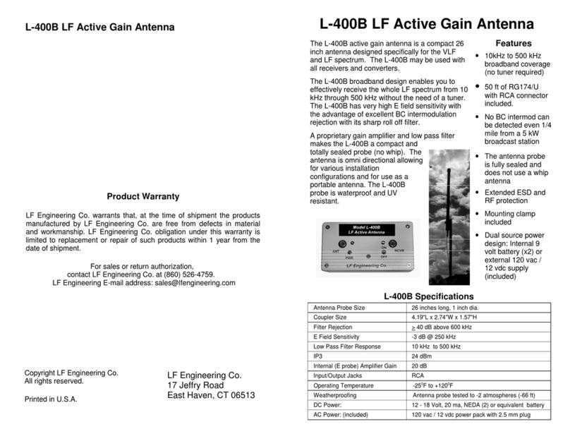
LF Engineering L-400B User manual

LF Engineering

LF Engineering L-400B User manual

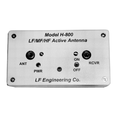
LF Engineering H-800 SKYMATCH User manual

LF Engineering

LF Engineering H-800 SKYMATCH User manual

Popular Antenna manuals by other brands

DIGITAL YACHT WL400 Installation & quick start guide

DIGITAL YACHT

DIGITAL YACHT WL400 Installation & quick start guide

Directive Systems & Engineering DSE2414LYRMK quick start guide

Directive Systems & Engineering

Directive Systems & Engineering DSE2414LYRMK quick start guide

ALDI cocoon  HE180247 instruction manual

ALDI

ALDI cocoon HE180247 instruction manual

Ubiquiti AirMax Sector quick start guide

Ubiquiti

Ubiquiti AirMax Sector quick start guide

Shure WA503 instruction sheet

Shure

Shure WA503 instruction sheet

NTI MegActiv MA305FT operating manual

NTI

NTI MegActiv MA305FT operating manual

Pioneer 90XM - AN - Satellite Radio Antenna owner's manual

Pioneer

Pioneer 90XM - AN - Satellite Radio Antenna owner's manual

ESCO Technologies ETS-Lindgren 3165-01 user manual

ESCO Technologies

ESCO Technologies ETS-Lindgren 3165-01 user manual

Array Solutions VHQ HEX Assembly instructions

Array Solutions

Array Solutions VHQ HEX Assembly instructions

COM-power corporation AH-8055 instruction manual

COM-power corporation

COM-power corporation AH-8055 instruction manual

Satcom SAILOR 100 GX quick start guide

Satcom

Satcom SAILOR 100 GX quick start guide

Novatel GPS-701-GGL user guide

Novatel

Novatel GPS-701-GGL user guide

APM APG-251215 Specification sheet

APM

APM APG-251215 Specification sheet

Alpha Antenna S9 user guide

Alpha Antenna

Alpha Antenna S9 user guide

Matchmaster Digimatch Explorer 01MM-DE7 installation instructions

Matchmaster

Matchmaster Digimatch Explorer 01MM-DE7 installation instructions

Winegard PR-7015 Specifications

Winegard

Winegard PR-7015 Specifications

FreeTec DA-5700 user manual

FreeTec

FreeTec DA-5700 user manual

Scout KS-60 2.0 Basic user manual

Scout

Scout KS-60 2.0 Basic user manual

manuals.online logo
manuals.online logoBrands
  • About & Mission
  • Contact us
  • Privacy Policy
  • Terms and Conditions

Copyright 2025 Manuals.Online. All Rights Reserved.