LG Chem EM048063P3S User manual

48 V Standalone Battery Module
Service Manual

About this manual
This manual describes how to service EM048063P3S and EM048126P3S series bat-
tery modules by LG Chem. Read this manual before you attempt to service the prod-
uct. If you are uncertain about any of the requirements, recommendations, or safety
procedures described in this manual, contact LG Chem immediately for advice and
clarication.
The information included in this manual is accurate at the time of publication. How-
ever, the product specications are subject to change without prior notice. In addi-
tion, the illustrations in this manual are meant to help explain system conguration
concepts. The illustrated items may dier from the actual items at the installation
location.
NOTE
The battery modules must communicate with its higher level system using the
required communication protocol.
2

Contents
1 Alerts by Status Indicators 4
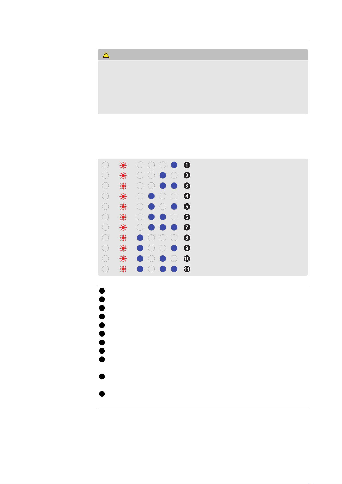
1.1 Abnormalstates................................ 4
1.1.1 Fault1states.............................. 5
1.1.2 Fault2states.............................. 6
1.2 Voltageabnormality ............................. 7
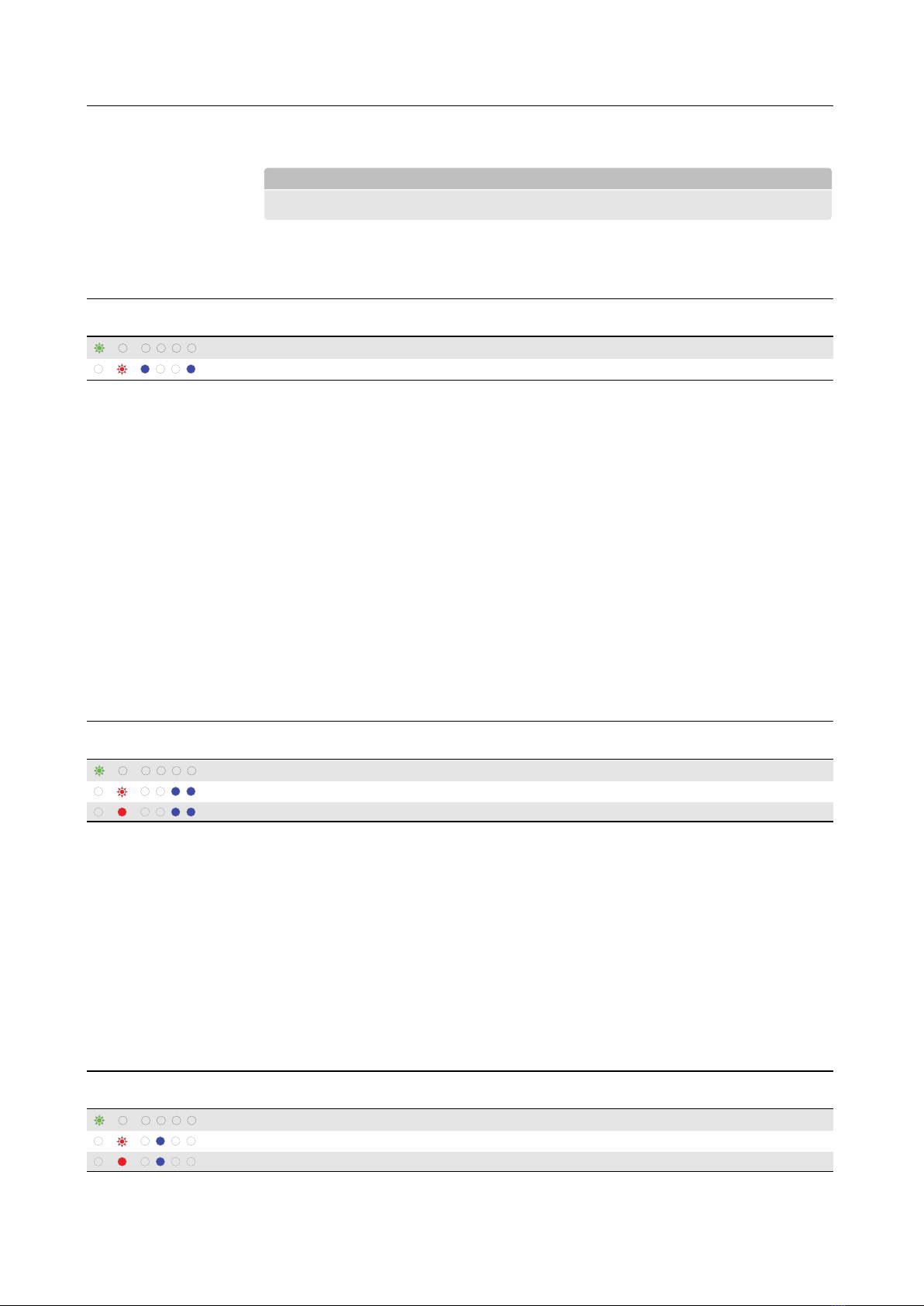
1.2.1 Cellovervoltage............................ 7
1.2.2 Cellundervoltage........................... 7
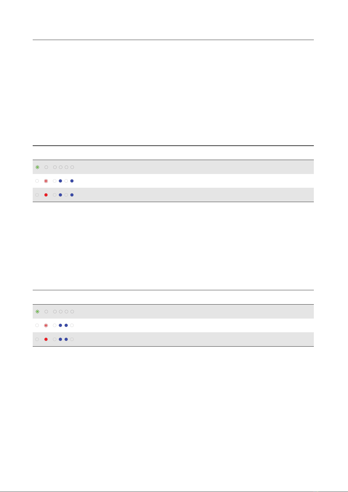
1.2.3 Too low module voltage . . . . . . . . . . . . . . . . . . . . . . . 7
1.2.4 Too large voltage dierence between cells . . . . . . . . . . . . . 8
1.3 Currentabnormality ............................. 8
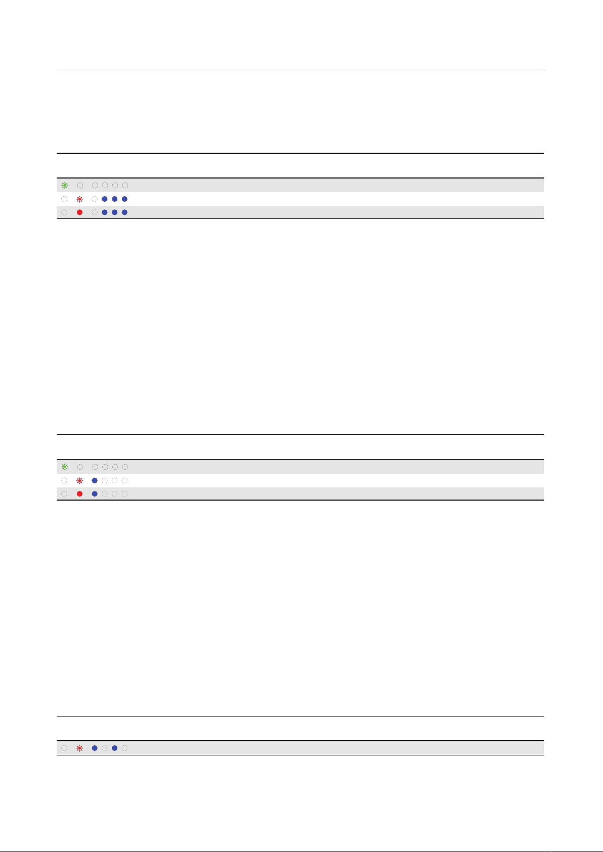
1.3.1 Over-charged current . . . . . . . . . . . . . . . . . . . . . . . . . 8
1.3.2 Over-discharged current . . . . . . . . . . . . . . . . . . . . . . . 8
1.3.3 Over-charged power . . . . . . . . . . . . . . . . . . . . . . . . . 9
1.3.4 Over-discharged power . . . . . . . . . . . . . . . . . . . . . . . 9
1.4 Temperature abnormality . . . . . . . . . . . . . . . . . . . . . . . . . . 10
1.4.1 Too high battery temperature . . . . . . . . . . . . . . . . . . . . 10
1.4.2 Too low battery temperature . . . . . . . . . . . . . . . . . . . . 10
1.4.3 Too large temperature dierence inside battery module . . . . . 10
1.5 Lostcommunication ............................. 11
1.5.1 Lost communication between battery modules . . . . . . . . . . 11
1.5.2 Lost communication with the higher level system . . . . . . . . 11
1.6 Stateofcharge................................. 12
1.6.1 ToolowSOC ............................. 12
1.6.2 ToohighSOC............................. 12
2 Replacements 13
2.1 Hot-swapping battery modules . . . . . . . . . . . . . . . . . . . . . . . 13
2.1.1 Identifying model number . . . . . . . . . . . . . . . . . . . . . . 13
2.1.2 Replacing a battery module . . . . . . . . . . . . . . . . . . . . . 13
2.2 Checkingfuse ................................. 14
2.3 ExpandingtheESS .............................. 15
2.4 ReducingtheESS ............................... 16
3 Formulas for Hot-Swapping 17
4 Block diagram of BMS 22
3

Chapter 1
Alerts by Status Indicators
The status indicators on the front of a battery module show its operating state.
Normal
SOC ≥ 75%
SOC ≥ 50%
SOC ≥ 25%
SOC < 25%
Voltage imbalance
Warning
Fault 1
Fault 2
Most problems are identied by the red and blue indicators. If a battery module
seems to not work properly but its red indicator neither ashes nor comes on solid,
check the fuse of the module. See Checking fuse on page 14.
1.1 Abnormal states
NOTE
Make sure the higher level system is properly congured in accordance with the
diagnosis tables in this manual so that it can limit the amount of charge or dis-
charge current in an abnormal state to avoid failure.
There are three levels of alerts:
Warning: When a battery module is likely to become unstable, it goes into a warning
state. This state is cleared when the module recovers its normal condition.
Fault 1: When a battery module is likely to become faulty, it goes into a low level
fault state, This state may require an appropriate measure to be cleared.
Fault 2: When a battery module falls outside prescribed limits, it goes into a high
level fault state. The battery module in this state is not used anymore.
4

Alerts by Status Indicators
CAUTION
Battery modules in a fault 2 state require an inspection by LG Chem. Faulty bat-
tery modules may be recovered and reused unless the cell voltage is less than
2.0 V. Unrecoverable faulty battery modules must be replaced with new ones im-
mediately. If not replaced immediately, faulty battery modules may decrease the
lifespan of the rest battery modules and cause safety problems. Contact LG Chem
or your distributor to order new battery modules for replacement.
1.1.1 Fault 1 states
When a battery module goes into a fault 1 state, the red indicator starts ashing and
the blue indicators show the fault number in binary form.
-
1The highest cell voltage is higher than the fault 1 level tolerance limit.
2The lowest cell voltage is lower than the fault 1 level tolerance limit.
3A current more than the fault 1 level tolerance limit is charged.
4A current more than the fault 1 level tolerance limit is discharged.
5A power more than the fault 1 level tolerance limit is charged.
6A power more than the fault 1 level tolerance limit is discharged.
7The battery temperature is higher than the fault 1 level tolerance limit.
8The battery temperature is lower than the fault 1 level tolerance limit.
9The dierence between the highest cell voltage and the lowest is larger than the
tolerance limit.
10 The temperature dierence inside the battery module is larger than the tolerance
limit.
11 Communication with other battery modules is lost for longer than the fault 1
level tolerance limit.
5

Alerts by Status Indicators
1.1.2 Fault 2 states
When a battery module goes into a fault 2 state, the red indicator comes on and the
blue indicators show the fault number in binary form.
1The highest cell voltage is higher than the fault 2 level tolerance limit.
2The lowest cell voltage is lower than the fault 2 level tolerance limit.
3A current more than the fault 2 level tolerance limit is charged.
4A current more than the fault 2 level tolerance limit is discharged.
5A power more than the fault 2 level tolerance limit is charged.
6A power more than the fault 2 level tolerance limit is discharged.
7The battery temperature is higher than the fault 2 level tolerance limit.
8The battery temperature is lower than the fault 2 level tolerance limit.
9The battery voltage is lower than the tolerance limit.
10 The hardware of the BMS is faulty.
11 Communication with other battery modules is lost for longer than the fault 2
level tolerance limit.
12 Communication with the higher level system is lost for longer than the tolerance
limit.
6

Alerts by Status Indicators
1.2 Voltage abnormality
1.2.1 Cell overvoltage
Indicators Alert Level Alert condition Charge
limit
Discharge
limit Release condition
Warning > 4.25 V for 3 s 0% 100% < 4.20 V for 3 s
Fault 1 > 4.28 V for 3 s 0% 100% < 4.25 V for 3 s
Fault 2 > 4.30 V for 3 s 0% 0%
The highest cell voltage is higher than the tolerance limit. At the fault 1 state, try
these steps:
1. Check the conditions of the battery module using any available method.
2. Manipulate the higher level system to discharge the ESS with a current less than
or equal to 63 A until the highest cell voltage is lower than 4.2 V.
3. Re-activate the ESS when the red indicator turns o.
If the problem persists, contact LG Chem for technical assistance.
1.2.2 Cell undervoltage
Indicators Alert Level Alert condition Charge
limit
Discharge
limit Release condition
Warning < 2.8 V for 3 s 100% 0% > 3.0 V for 3 s
Fault 1 < 2.6 V for 3 s 100% 0% > 2.8 V for 3 s
Fault 2 < 2.4 V for 3 s 0% 0%
The lowest cell voltage is lower than the tolerance limit. At the fault 1 state, try these
steps:
1. Check the conditions of the battery module using any available method.
2. Manipulate the higher level system to charge the ESS with a current less than or
equal to 63 A until the lowest cell voltage is higher than 3 V.
3. Re-activate the ESS when the red indicator turns o. The ESS recharges for 10
minutes before performing a diagnosis after it is activated.
If the problem persists, contact LG Chem for technical assistance.
NOTE
The battery module turns o 10 minutes after going into the fault 2 state.
1.2.3 Too low module voltage
Indicators Alert Level Alert condition Charge
limit
Discharge
limit Release condition
Fault 2 < 29.0 V for 3 s 0% 0%
7

Alerts by Status Indicators
The module voltages is lower than the tolerance limit.
NOTE
The battery module turns o 10 minutes after going into the fault 2 state.
1.2.4 Too large voltage dierence between cells
Indicators Alert Level Alert condition Charge
limit
Discharge
limit Release condition
Warning > 0.3 V for 3 s 50% 50% < 0.2 V for 3 s
Fault 1 > 0.5 V for 3 s 0% 0% < 0.3 V for 3 s
When the lowest cell voltage is higher than 3.5 V, the dierence between the highest
cell voltage and the lowest cell voltage is larger than the tolerance limit. At the fault
1 state, try these steps:
1. Check the conditions of the battery module using any available method.
2. Shut o the higher level system and wait until cell balancing is completed.
3. Re-activate the ESS when the red indicator turns o.
If the problem persists, contact LG Chem for technical assistance.
1.3 Current abnormality
1.3.1 Over-charged current
Indicators Alert Level Alert condition Charge
limit
Discharge
limit Release condition
Warning > 68.8 A for 3 s 0% 100% < 66.1 A for 3 s
Fault 1 > 71.4 A for 3 s 0% 100% < 68.8 A for 3 s
Fault 2 > 74.1 A for 3 s 0% 0%
A current more than the tolerance limit is charged. At the fault 1 state, try these steps:
1. Check the conditions of the battery module using any available method.
2. Set the maximum charge current to less than 63 A on the higher level system.
3. Re-activate the ESS when the red indicator turns o.
If the problem persists, contact LG Chem for technical assistance.
1.3.2 Over-discharged current
Indicators Alert Level Alert condition Charge
limit
Discharge
limit Release condition
Warning > 68.8 A for 3 s 100% 0% < 66.1 A for 3 s
Fault 1 > 71.4 A for 3 s 100% 0% < 68.8 A for 3 s
Fault 2 > 74.1 A for 3 s 0% 0%
8

Alerts by Status Indicators
A current more than the tolerance limit is discharged. At the fault 1 state, try these
steps:
1. Check the conditions of the battery module using any available method.
2. Set the maximum discharge current to less than 63 A on the higher level system.
3. Re-activate the ESS when the red indicator turns o.
If the problem persists, contact LG Chem for technical assistance.
1.3.3 Over-charged power
Indicators Alert Level Alert condition Charge
limit
Discharge
limit Release condition
Warning > Charge power limit × 110% W
for 40 s 0% 100% < Charge power limit × 0% W or
155.4 W for 3 s
Fault 1 > Charge power limit × 115% W
for 40 s 0% 100% < Charge power limit × 0% W or
155.4 W for 3 s
Fault 2 > Charge power limit × 120% W
for 40 s 0% 0%
A power more than the tolerance limit is charged. Only with the residential models
including EM048063P3S2 and EM048126P3S7, at the fault 1 state, try these steps:
1. Check the conditions of the battery module using any available method.
2. Make sure that the higher level system is properly congured not to exceed the
maximum charge power of the battery module.
1.3.4 Over-discharged power
Indicators Alert Level Alert condition Charge
limit
Discharge
limit Release condition
Warning > Discharge power limit × 110%
W for 40 s 0% 100% Discharge power limit × 0% W or
155.4 W for 3 s
Fault 1 > Discharge power limit × 115%
W for 40 s 0% 100% Discharge power limit × 0% W or
155.4 W for 3 s
Fault 2 > Discharge power limit × 120%
W for 40 s 0% 0%
A power more than the tolerance limit is discharged. Only with the residential mod-
els including EM048063P3S2 and EM048126P3S7, at the fault 1 state, try these steps:
1. Check the conditions of the battery module using any available method.
2. Make sure that the higher level system is properly congured not to exceed the
maximum discharge power of the battery module.
9

Alerts by Status Indicators
1.4 Temperature abnormality
1.4.1 Too high battery temperature
Indicators Alert Level Alert condition Charge
limit
Discharge
limit Release condition
Warning > 50.0°C for 3 s 50% 50% < 48.0°C for 3 s
Fault 1 > 55.0°C for 3 s 0% 0% < 50.0°C for 3 s
Fault 2 > 60.0°C for 3 s 0% 0%
The battery temperature is higher than the tolerance limit. At the fault 1 state, try
these steps:
1. Check the conditions of the battery module using any available method.
2. Check the ambient temperature.
3. Run the air conditioner until the ambient temperature drops below 30°C.
4. Deactivate the ESS and wait for 2 hours until the battery module cools down.
5. Re-activate the ESS.
If the problem persists, contact LG Chem for technical assistance.
1.4.2 Too low battery temperature
Indicators Alert Level Alert condition Charge
limit
Discharge
limit Release condition
Warning < −12.0°C for 3 s 50% 50% > −10.0°C for 3 s
Fault 1 < −15.0°C for 3 s 0% 0% > −12.0°C for 3 s
Fault 2 < −20.0°C for 3 s 0% 0%
The battery temperature is lower than the tolerance limit. At the fault 1 state, try
these steps:
1. Check the conditions of the battery module using any available method.
2. Check the ambient temperature.
3. Run the air conditioner until the ambient temperature rises above 18°C.
4. Deactivate the ESS and wait for 2 hours until the battery module warms up.
5. Re-activate the ESS.
If the problem persists, contact LG Chem for technical assistance.
1.4.3 Too large temperature dierence inside battery module
Indicators Alert Level Alert condition Charge
limit
Discharge
limit Release condition
Fault 1 > 10.0°C for 3603 s 0% 0% < 5.0°C for 3 s
10

Alerts by Status Indicators
The temperature dierence inside the battery module is larger than the tolerance
limit. At the fault 1 state, try these steps:
1. Check the conditions of the battery module using any available method.
2. Make sure that no heating or cooling source is nearby.
3. Deactivate the ESS and wait for around 2 hours until the temperature dierence
is reduced to less than 5°C.
4. Re-activate the ESS.
If the problem persists, contact LG Chem for technical assistance.
1.5 Lost communication
1.5.1 Lost communication between battery modules
Indicators Alert Level Alert condition Charge
limit
Discharge
limit Release condition
Fault 1 Lost communication for 10 s 0% 0% Resumed for 1 s
Fault 2 Lost communication for 50 s 0% 0%
Communication with other battery modules is lost for longer than the tolerance limit.
1. Check the conditions of the battery module using any available method.
2. Deactivate the ESS.
3. Make sure that the intra-rack communication cables are properly connected be-
tween the battery modules.
4. Re-activate the ESS.
1.5.2 Lost communication with the higher level system
Indicators Alert Level Alert condition Charge
limit
Discharge
limit Release condition
Fault 2 Lost communication for 610 s 0% 0%
Communication with the higher level system is lost for longer than the tolerance
limit.
1. Check the conditions of the battery module using any available method.
2. Deactivate the ESS.
3. Make sure that the higher level communication cable is properly connected be-
tween the master module and the higher level system.
4. Re-activate the ESS.
11

Alerts by Status Indicators
1.6 State of charge
1.6.1 Too low SOC
Indicators Alert Level Alert condition Charge
limit
Discharge
limit Release condition
Warning < 2.0% for 10 s 100% 50% > 3.0% for 10 s
The SOC is lower than the tolerance limit.
1. Check the blue indicators to see the SOC.
2. Manipulate the higher level system to charge the ESS with a current less than or
equal to 63 A until the SOC is higher than or equal to 3%.
1.6.2 Too high SOC
Indicators Alert Level Alert condition Charge
limit
Discharge
limit Release condition
Warning > 99.0% for 10 s 50% 100% < 98.0% for 10 s
The SOC is higher than the tolerance limit.
1. Check the blue indicators to see the SOC.
2. Manipulate the higher level system to discharge the ESS with a current less than
or equal to 63 A until the SOC is lower than or equal to 98%.
12

Chapter 2
Replacements
2.1 Hot-swapping battery modules
2.1.1 Identifying model number
To ensure that a new battery module is the same model as the old ones, verify the
new module’s model number.
1. Press the On/O button on the new battery module to activate it. The green indi-
cator turns on rst and then the rightmost blue indicator turns on a few seconds
later.
2. Press and hold the On/O button for longer than 5 seconds. While the button
is pressed, the blue indicators show the last digit of the model number in binary
form.
2.1.2 Replacing a battery module
NOTE
Hot-swapping is permitted only with EM048063P3S1 and EM048126P3S6 models.
Replace a faulty battery module only when less than 1 A of current ows into or out
of it. This indicates that the battery module is neither charging nor discharging.
To replace a battery module, follow these steps:
13

Replacements
1. Holding the button on the connector of the
positive cable, pull out the connector to re-
move the cable from the module. Remove
the negative cable using the same method.
2. Press the On/O button on the module to
deactivate it.
3. Remove the communication cables from the
module.
4. Loosen the screws at the brackets on both
sides of the module to remove the module
from the rack.
5. Replace the module with a new one and fas-
ten the brackets.
6. Connect the communication cables to the
new module.
7. Press the On/O button on the module to
activate it. If some of the blue indicators
ash, the module is the wrong model. See
Identifying model number on page 13.
8. Connect the power cables to the module.
CAUTION
Do not replace two or more battery modules simultaneously. Replace modules
one by one, repeating this replacement procedure.
2.2 Checking fuse
To check and replace the fuse of a battery module, follow these steps:
1. Loosen the M4 screw at the top center of the
rear of the battery module.
2. Loosen the four M6 screws at each corner of
the rear.
3. Remove the back panel.
14

Replacements
4. Slide the right panel to the back to remove it.
5. Remove the fuse cover by pulling it out.
6. Loosen the three nuts that secure the fuse
and the negative cable.
7. Pull out the fuse.
8. Measure the resistance of the fuse to see if it
is blown.
9. If the fuse is blown, insert a new fuse into the
fuse holder.
10. Reassemble in the reverse order of the disas-
sembly procedure.
2.3 Expanding the ESS
To expand the ESS by adding more battery modules, follow these steps:
1. Press and hold the On/O button on the master module for longer than 5 seconds
to deactivate the ESS.
2. Shut o the higher level system.
3. Install new battery modules in the rack.
4. Re-activate the ESS.
CAUTION
Never fail to keep this sequence unchanged.
15

Replacements
2.4 Reducing the ESS
To reduce the ESS by removing some battery modules, follow these steps:
1. Press and hold the On/O button on the master module for longer than 5 seconds
to deactivate the ESS.
2. Shut o the higher level system.
3. Remove the unwanted battery modules.
4. Re-activate the ESS.
CAUTION
Never fail to keep this sequence unchanged.
16

Chapter 3
Formulas for Hot-Swapping
One battery module can accommodate up to 63 A. If the amount of current that each
of the remaining modules has to accommodate exceeds 63 A, hot-swapping is not
allowed. The following formula calculates the maximum current per module that
allows hot-swapping.
The maximum current that allows hot-swapping
= the higher-level system’s current ÷ (the number of modules installed − the
number of faulty modules that should be replaced)
For example, if two modules are faulty and the higher-level system’s current is 120 A
when six modules are installed, the maximum current during hot-swapping is 30 A.
120 A ÷ (6 - 2)
= 30 A
Use the following formula to determine how many faulty modules can be replaced
at a time.
The number of hot-swappable modules
= the number of modules installed − (the higher-level system’s current ÷ 63 A)
All the decimal places should be removed from the result without rounding. For
example, if two modules are installed and the higher-level system’s current is 70 A,
no modules can be replaced.
2 − (70 A ÷ 63 A)
= 0.89 = 0
If four modules are installed and the higher-level system’s current is 80 A, two faulty
modules can be replaced at a time.
4 − (80 A ÷ 63 A)
= 2.73 = 2
Use the following tables for quick reference when hot-swapping faulty battery mod-
ules.
17

Formulas for Hot-Swapping
In case of 2 battery modules
Higher-level system current
(A)
The maximum current
during hot-swapping (A)
The number of replaceable
modules
55 55 1
60 60 1
65 65 0
In case of 4 battery modules
Higher-level system current
(A)
The maximum current
during hot-swapping (A)
The number of replaceable
modules
60 60 3
70 35 2
80 40 2
90 45 2
100 50 2
110 55 2
120 60 2
130 43.3 1
140 46.7 1
150 50 1
160 53.3 1
170 56.7 1
180 60 1
190 63.3 0
In case of 6 battery modules
Higher-level system current
(A)
The maximum current
during hot-swapping (A)
The number of replaceable
modules
60 60 5
70 35 4
80 40 4
90 45 4
100 50 4
110 55 4
120 60 4
130 43.3 3
140 56.7 3
150 50 3
160 53.3 3
170 56.7 3
180 60 3
190 47.5 2
210 52.5 2
18

Formulas for Hot-Swapping
220 55 2
230 57.5 2
240 60 2
250 62.5 2
260 52 1
270 54 1
280 56 1
290 58 1
300 60 1
310 62 1
320 64 0
In case of 8 battery modules
Higher-level system current
(A)
The maximum current
during hot-swapping (A)
The number of replaceable
modules
60 60 7
70 35 6
80 40 6
90 45 6
100 50 6
110 55 6
120 60 6
130 43.3 5
140 46.7 5
150 50 5
160 53.3 5
170 56.7 5
180 60 5
190 47.5 4
200 50 4
210 52.5 4
220 55 4
230 57.5 4
240 60 4
250 62.5 4
260 52 3
270 54 3
280 56 3
290 58 3
300 60 3
310 62 3
320 53.3 2
330 55 2
340 56.7 2
350 58.3 2
360 60 2
19

Formulas for Hot-Swapping
370 61.7 2
380 54.3 1
390 55.7 1
400 57.1 1
410 58.6 1
420 60 1
430 61.4 1
440 62.9 1
450 64.3 0
In case of 10 battery modules
Higher-level system current
(A)
The maximum current
during hot-swapping (A)
The number of replaceable
modules
60 60 9
70 35 8
80 40 8
90 45 8
100 50 8
110 55 8
120 60 8
130 43.3 7
140 46.7 7
150 50 7
160 53.3 7
170 56.7 7
180 60 7
190 47.5 6
200 50 6
210 52.5 6
220 55 6
230 57.5 6
240 60 6
250 62.5 6
260 52 5
270 54 5
280 56 5
290 58 5
300 60 5
310 62 5
320 53.3 4
330 55 4
340 56.7 4
350 58.3 5
360 60 4
370 61.7 4
380 54.3 3
20
Other manuals for EM048063P3S
1
This manual suits for next models
1
Table of contents
Other LG Chem Camera Accessories manuals

LG Chem
LG Chem 6.4 EX User manual

LG Chem
LG Chem RESU10H StorEdge User manual

LG Chem
LG Chem RESU10H StorEdge Assembly instructions

LG Chem
LG Chem RESU HV Product guide

LG Chem
LG Chem RESU7H StorEdge User manual

LG Chem
LG Chem RESU7H StorEdge User manual

LG Chem
LG Chem RESU10M User manual

LG Chem
LG Chem INR18650 MH1 Owner's manual

LG Chem
LG Chem RESU10H Series User manual