LG Chem RESU7H StorEdge User manual

1
StorEdge™ Inverter Wiring Guide & On Site Checklist for Europe, APAC, South Africa
This document is a battery wiring guide and contains an on-site checklist with steps for post-installation verification of a StorEdge system for the following batteries:
LG Chem RESU7H/RESU10H
For more details, please refer to the StorEdge Installation Guide supplied with the StorEdge Inverter. For additional assistance contact SolarEdge Support (see page 8).
Wiring Guide
WARNING!
For LG Chem RESU7H/RESU10H batteries:
Before wiring the system, make sure that the battery is powered off, using both of the following switches:
* Auxiliary power supply switch
* Circuit breaker switch
Figure 1: LG Chem Auxiliary Power Switch and Circuit Breaker Switches

StorEdge Inverter Wiring and On Site Checklist
2
Wiring Types and Connectors
To connect the battery to the StorEdge Inverter, use the following wiring types and connectors:
Recommended Cable Type (min-max cross section)
SolarEdge Connector
LG Chem RESU7H/RESU10H Battery
Connector
DC: 6 mm2(2.5-6 mm2), 600V insulated
BAT DC +
DC +
BAT DC -
DC -
Ground
Control and monitoring:
5-wire shielded twisted pair cable, 0.2 mm2(0.2-1.5 mm2), 600V insulated.
CAT5 600V insulated can also be used.
En (enable)
ENABLE_H
V+
Not connected
B- (RS485)
RS485_L
A+ (RS485)
RS485_H
G (RS485) or Thermal (depending on inverter type)
EN_G
Wiring Diagrams –Connecting Batteries to the StorEdge Inverter
The diagrams on the following pages illustrate the connection of batteries to the StorEdge system. The following table will help you find the appropriate wiring diagram
for your system configuration. Pay attention to whether the battery DIP switch setup on the communication unit main board has 2 or 3 switches.
Battery Type
Connected to
Wiring Diagram
DIP Switches
LG Chem RESU7H/RESU10H
StorEdge Inverter with 2 DIP Switches
See Figure 2 on page 3
StorEdge Inverter with 3 DIP Switches
See Figure 3 on page 3

StorEdge Inverter Wiring and On Site Checklist
3
Connecting the LG Chem RESU7H/RESU10H to a StorEdge Inverter with Two DIP Switches and SolarEdge Meter
0.2 mm² 300VG <> G
StorEdge Inverter SolarEdge Modbus Meter
B- <> B- and A+ <> A+ on the same twisted pair
RS485_H <> A+ and RS485_L <> B- on the same twisted pair
ENABLE_H <> En
EN_GND <> Thermal
0.2 mm² 600V
LG Chem Battery
2 DIP
Switches
RS485-terminated
B A G
Figure 2: Connecting the LG Chem RESU7H/RESU10H to a StorEdge Inverter with Two DIP Switches and SolarEdge Meter
Connecting the LG Chem RESU7H/RESU10H to a StorEdge Inverter with Three DIP Switches and SolarEdge Meter
0.2 mm² 300VG <> G
StorEdge Inverter SolarEdge Modbus Meter
B- <> B- and A+ <> A+ on the same twisted pairRS485_H <> A+ and RS485_L <> B- on the same twisted pair
ENABLE_H <> En
EN_GND <> G
0.2 mm² 600V
LG Chem Battery
3 DIP
Switches
RS485-terminated
B A G
Figure 3: Connecting the LG Chem RESU7H/RESU10H to a StorEdge Inverter with Three DIP Switches and SolarEdge Meter

StorEdge Inverter Wiring and On Site Checklist
4
Switch Settings
Setting the DIP Switches on the Inverter Communication Board
Set DIP switch SW7
SW7
RS485-1
RS485-2
For RS485-1 connections, use DIP Switch 1 (leftmost):
* ON (up): Terminated (no meter installed)
* OFF (down): Not terminated (meter is installed)
For RS485-2 connections, use DIP Switch 2 (rightmost):
* ON (up): Terminated (no meter installed)
* OFF (down): Not terminated (meter is installed)
Setting the DIP Switches on the Inverter Connection Unit Main Board (with Two or Three DIP Switches)
DIP Switch 1 (leftmost)
DIP Switch 2 (rightmost)
DIP Switch 1 (leftmost)
DIP Switch 2 (center)
DIP Switch 3 (rightmost)
ON (up)
ON (up)
ON (up)
ON (up)
ON (up)

StorEdge Inverter Wiring and On Site Checklist
5
Post Installation Verification and Configuration
Follow the checklist below to verify that the system is properly connected and configured. The checklist is suitable for a backup system with a single StorEdge Inverter, a
single battery, and a single SolarEdge Modbus Meter installed at the grid connection point.
For other system configurations, follow the steps in the StorEdge Installation Guide supplied with the StorEdge Inverter.
Step
Verification Action
Checked
1
Installation and Wiring
1.1
Verify the distance between components complies with the distances detailed in the supplied installation guide.
1.2
Take a photograph of the battery connection area and send to SolarEdge support (useful for future debugging if necessary).
1.3
Take a photograph of the connection area of the StorEdge Inverter and send it to SolarEdge support.
1.4
Take a photograph of the installation and send it to SolarEdge support.
1.5
Verify that the battery splash cover is closed.
1.6
Verify that the backed-up loads panel is wired (relevant for backup systems only).
1.7
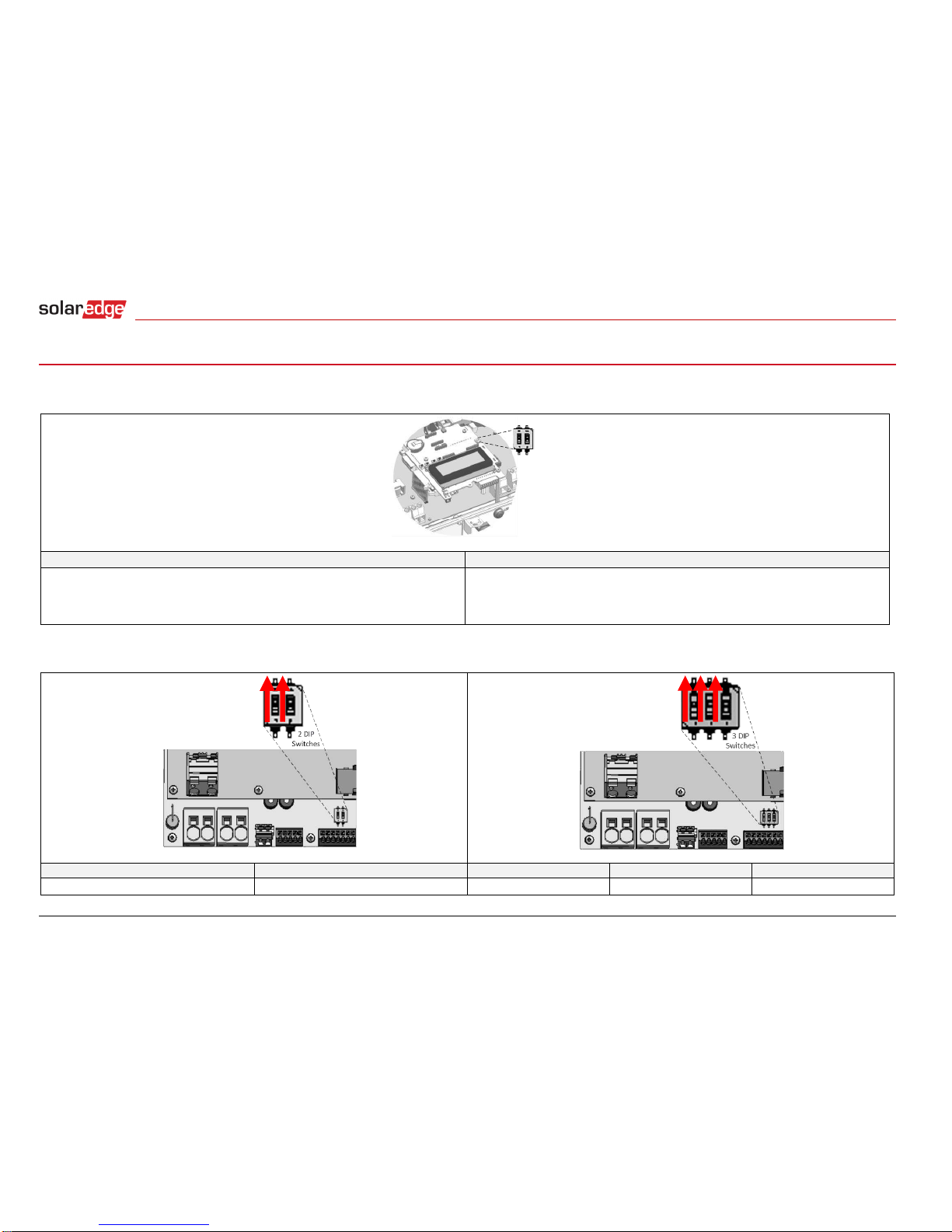
Verify that the StorEdge Inverter’s DIP switches are configured as shown on page 4.
1.8
Verify that all DC, communication and AC cabling connections are completed as follows:
1.8.1
Check AC wiring and circuit breaker.
1.8.2
Check string DC input voltage. Expect 1V per optimizer in the string.
1.8.3
Verify that grounding is properly connected in the battery and inverter.
1.8.4
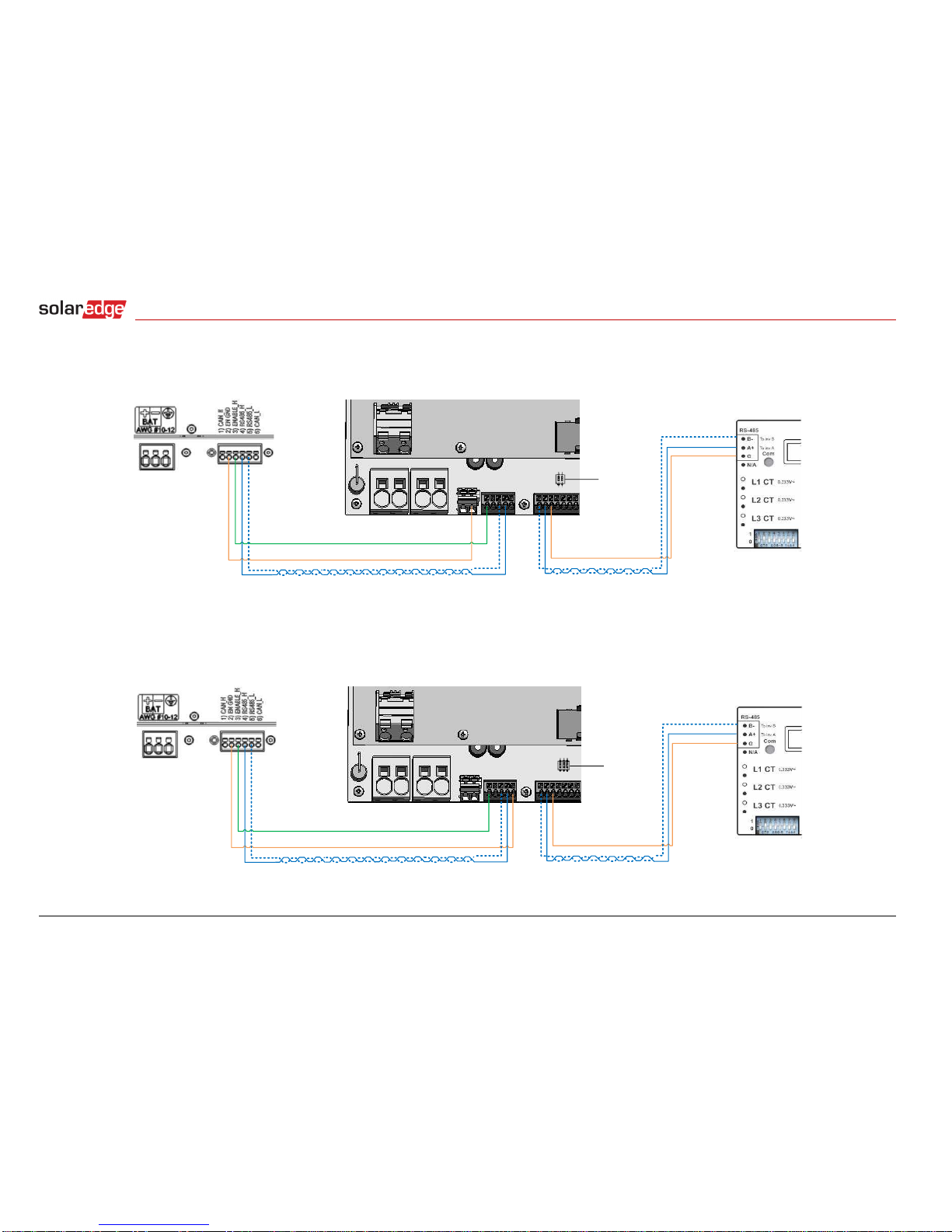
Check the DC wiring to the battery, according to the wiring diagram you selected from the table on page 4. Check the connections and verify that
all are securely connected.
1.8.5
Check connections to the battery and the switch setup as described earlier in this document.
1.8.6
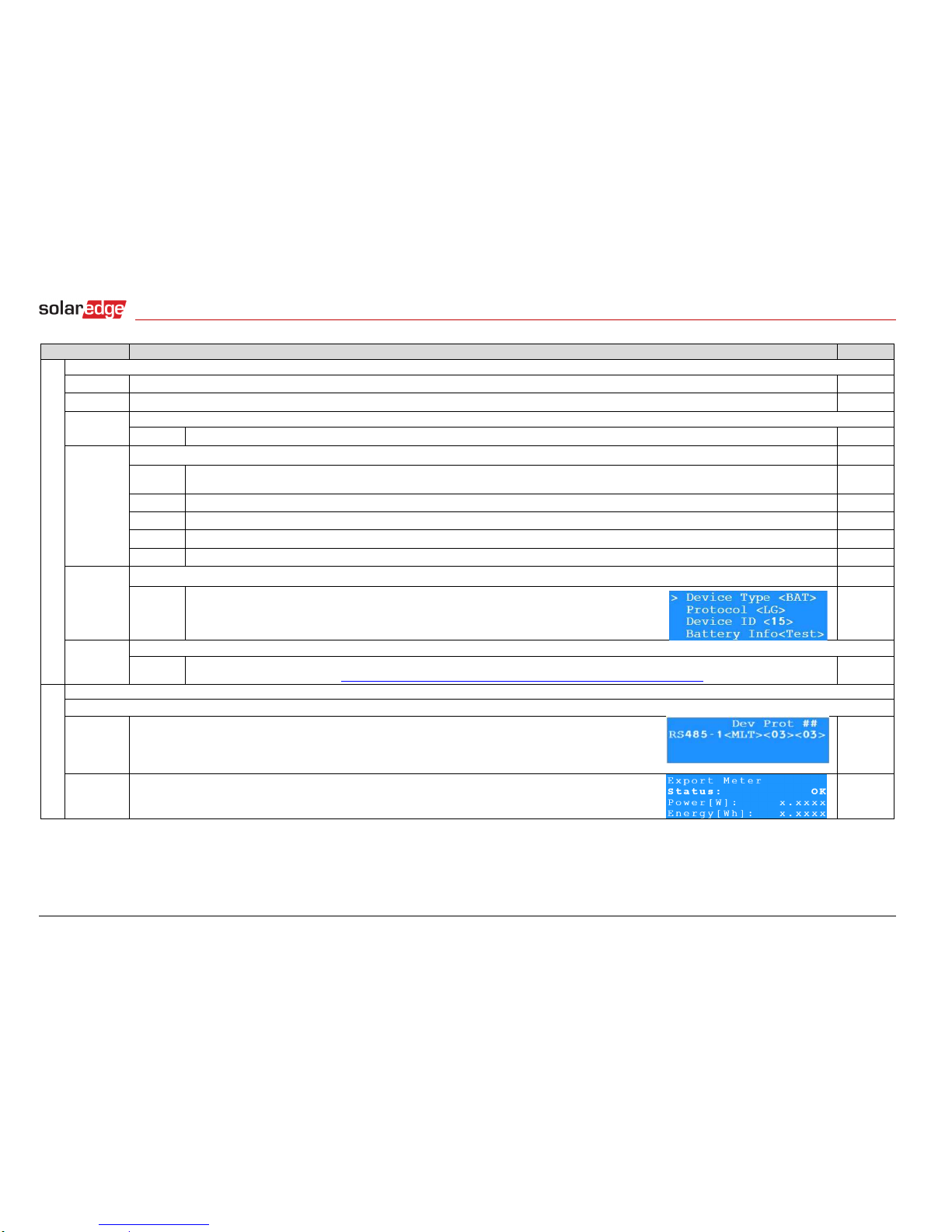
Check connections to the meter. If no meter is connected, the inverter’s RS485 bus must be terminated using the DIP switches (see page 4).
1.8.7
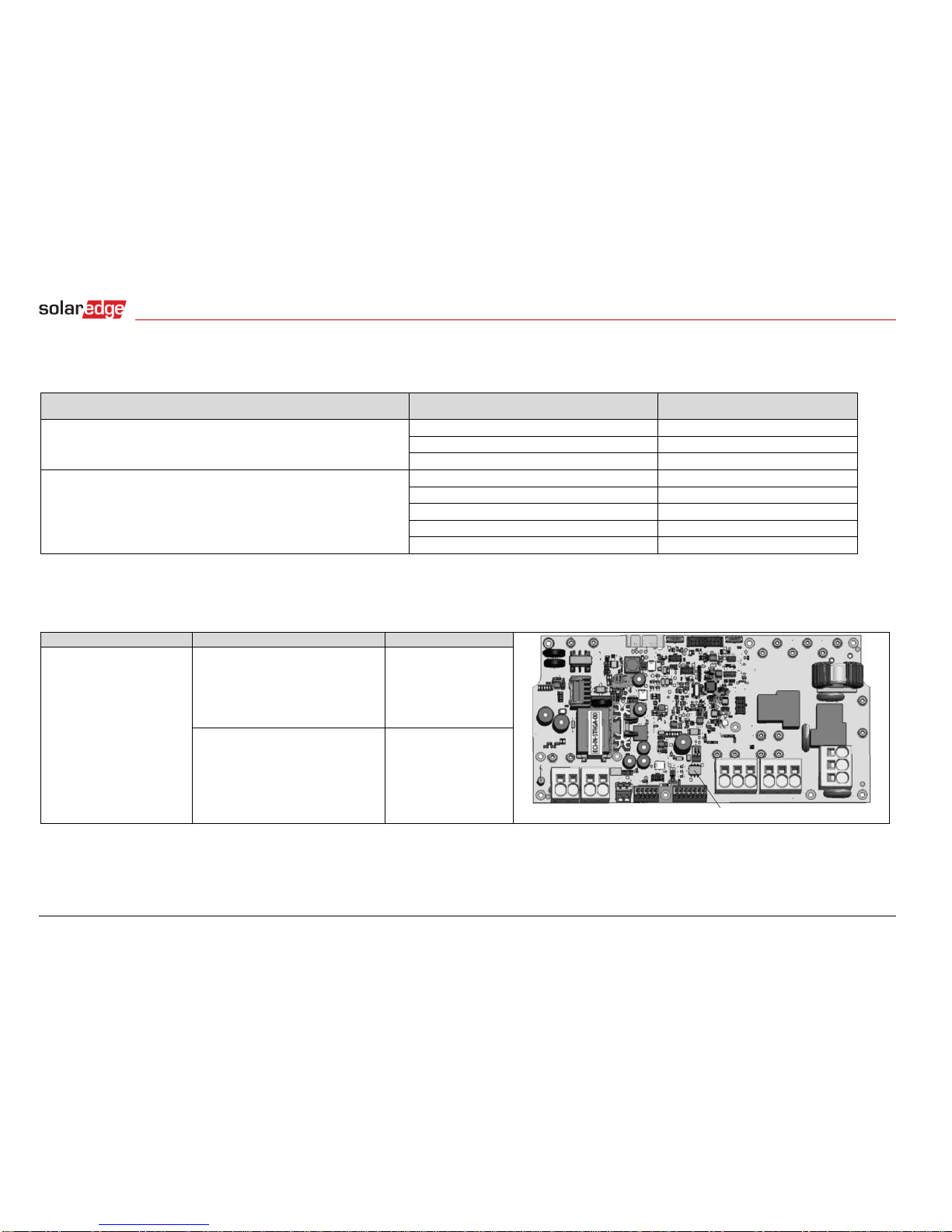
Check that a 9V battery is installed in the StorEdge Inverter.
1.8.8
Check meter AC and CT connections including CT direction: Connect the meter to power supply. Check the LEDs: when configured as
export/import meter: green=import, red=export.
1.8.9
Check connection to the Internet with one of the following options: Ethernet, Wi-Fi, Cellular, ZigBee Module. The connection status displayed
should be S_OK.
2
Commissioning
2.1
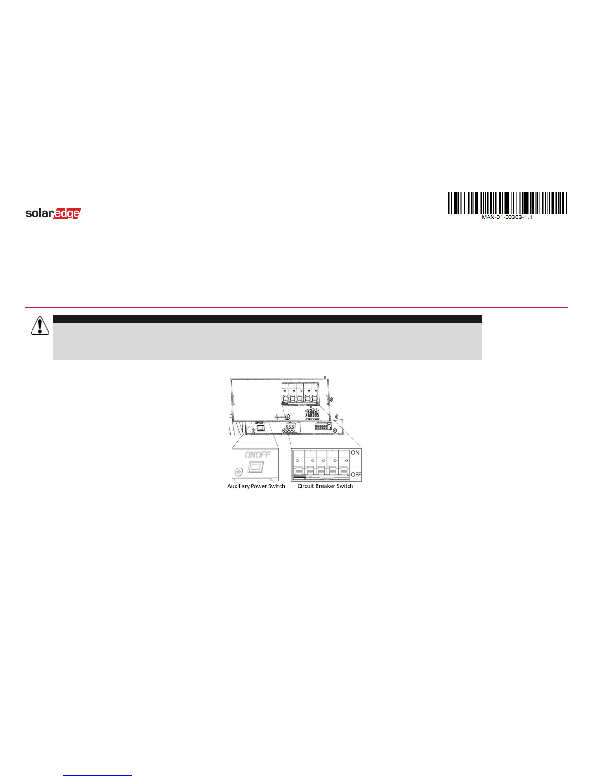
LG Chem Battery: Switch on Auxiliary power supply and Circuit breaker switch, as shown in Figure 1.
2.2
Activate the inverter using the supplied activation card.
2.3
Switch on the inverter AC.
2.4
Perform pairing when the modules are exposed to sunlight.

StorEdge Inverter Wiring and On Site Checklist
6
Step
Verification Action
Checked
3
RS485 Configuration Verification (for one Battery and one Export + Import meter)
3.1
If not already OFF, switch OFF the StorEdge Connection Unit switch (for StorEdge inverter).
3.2
Switch the inverter ON/OFF switch to OFF.
3.3
Devices
3.3.1
Enter Setup mode and select Communication > RS485-1 Conf > Multi Devices
3.4
Meter
3.4.1
Select Communication > RS485-1 > Meter 2 > Meter ID: 2, Device Type <MTR>, Protocol <WN>, CT Rating (as per CT label), Device ID <2>,
Meter Function (E+I).
3.4.2
Verify Device Type > Revenue Meter
3.4.3
Verify Protocol > Meter
3.4.4
Verify that the CT value matches the value that appears on the CT label: CT Rating > <xxxxA>.
3.4.5
If CT resets to 0, check the communication with the meter.
3.5
Battery
3.5.1
Select Communication > RS485-1 > Battery 1 > Protocol (LG Battery).
Select Communication > RS485-1 > Battery 1 > Battery ID (15).
3.6
Optional: RS485 Expansion Kit
3.6.1
For a system with multiple inverters that has a single RS485 bus only, install and configure an RS485 Expansion Kit. Refer to the RS485
Expansion Kit Installation Guide. http://www.solaredge.com/files/pdfs/RS485_expansion_kit_installation_guide.pdf
4
RS485 Connection Verification
Press the inverter external LCD light button to display the status screens one after the other until a screen like the following is displayed:
4.1
Check the RS485 communication status:
Verify that the number under Prot displays the number of configured devices.
Verify that the number under ## displays the number of communicating devices.
4.2
Check the meter(s): In the meter(s) status screen check that the status is OK. If Comm. Error appears, refer to the
troubleshooting section in the supplied installation guide.

StorEdge Inverter Wiring and On Site Checklist
7
5
Check Battery Connection
5.1
Scroll through the menus until you reach the battery status screen. Check the battery information: BSN (battery
serial number), ID (15 for LG), SOE (battery capacity in percentage), PWR (charge/discharge power), Total (total
discharged energy) and the State (Charging/Discharging, Idle, Init or Fault).
6
Inverter + Battery Firmware Upgrade
6.1
Insert a micro SD card with the latest firmware version available on http://solaredge.com/storedge/firmware.
6.2
Close the inverter cover.
6.3
Switch on the inverter ON/OFF switch.
6.4
Using the external LCD light button enter Setup mode and select Maintenance > SW upgrade >
Yes, wait for running script to finish, duration: 30 minutes.
Battery Firmware Version Check
6.5
Switch OFF the inverter and wait 3 minutes.
6.6
Select Communication > RS485-1 > Battery 1 > Battery Info
7
Setup StorEdge Operating Mode
7.1
Turn ON the inverter.
7.2
Use the status screens to check charge or discharge according to the current condition.
7.3
Set up the operating mode according to one of the following options:
Maximize Self Consumption
7.3.1
Select Power Control > Energy Manager > Energy Control > Max self-Consume
Charge/Discharge Profile Programming
7.3.2
Select Power Control > Energy Manager > Energy Control > Time of Use
Backup Only
7.3.3
Select Power Control > Energy Manager > Energy Control > Backup only
7.4
Optional: Set additional StorEdge options
AC Charge
7.4.1
Select Power Control > Energy Manager > Storage Ctrl > AC Charge > Enable
Backup reserve
7.4.1
Select Power Control > Energy Manager > Storage Ctrl > Backup Rsvd > {Value}

StorEdge Inverter Wiring and On Site Checklist
8
Support and Contact Information
Australia (+61)
1800 465 567
APAC (Asia Pacific) (+972)
073 2403118
China (+86)
21 6212 5536
France and Belgium (+33)
0800 917 410
DACH and Rest of Europe (+49)
089 454 59730
Italy (+39)
0422 053700
Japan (+81)
03 5530 9360
Netherlands (+31)
0800 0221 089
New Zealand (+64)
0800 144 875
United Kingdom (+44)
0800 028 1183
US & Canada (+1)
510 498 3200
Greece (+30)
00800 125574
Middle East & Africa (+972)
073 2403118
South Africa (+27)
0800 982 659
Turkey(+972)
073 240 3118
Worldwide (+972)
073 240 3118
Before contact, make sure to have the following information at hand:
Inverter and power optimizer model numbers
Serial number of the product in question
The error indicated on the inverter screen or on the SolarEdge monitoring portal, if there is such an indication.
System configuration information, including the type and number of modules connected and the number and length of strings.
The communication method to the SolarEdge monitoring portal, if the site is connected
Inverter software version as appears in the ID status screen.
Other manuals for RESU7H StorEdge
3
This manual suits for next models
1
Table of contents
Other LG Chem Camera Accessories manuals

LG Chem
LG Chem RESU10H Series User manual

LG Chem
LG Chem EM048063P3S User manual

LG Chem
LG Chem RESU HV Product guide

LG Chem
LG Chem 6.4 EX User manual

LG Chem
LG Chem RESU7H StorEdge User manual

LG Chem
LG Chem RESU10H StorEdge User manual

LG Chem
LG Chem RESU10H StorEdge Assembly instructions

LG Chem
LG Chem INR18650 MH1 Owner's manual

LG Chem
LG Chem RESU10M User manual