LG 3828A20229B User manual

P/No.: 3828A20229B

LG Single Packaged-Type
Air Conditioner
INSTALLATION MANUAL
LG
IMPORTANT
• Please read this installation manual completely before
installing the product.
• When the power device is damaged, replacement work
shall be performed by authorized personnel only.
• Installation work must be performed in accordance with
the national wiring standards by authorized personnel
only.
• Please retain this installation manual for future reference
after reading it thoroughly.

2Single Package Type Air Conditioner
Single Package Type Air Conditioner Installation Manual
TABLE OF CONTENTS
Safety Precautions .................................................................................................3
Introduction.............................................................................................................8
Symbols Used in this Manual ...............................................................................8
Features ................................................................................................................8
Dimensional Data ...................................................................................................9
Installation of Unit................................................................................................10
Inspection............................................................................................................10
Location and Recommendations ........................................................................10
Ductwork .............................................................................................................11
Condensate Drain Piping....................................................................................11
Filter Installation .................................................................................................12
Electrical Wiring ..................................................................................................12
Start-Up Pre-Start Quick Check List...................................................................16
Starting the Unit..................................................................................................17
Final Installation Checklist and Maintenance......................................................18

Safety Precautions
Installation Manual 3
To prevent injury to the user or other people and property damage, the following instructions must be
followed.
■Be sure to read before installing the air conditioner.
■Be sure to observe the cautions specified here as they include important items related to safety.
■Incorrect operation due to ignoring instruction will cause harm or damage. The seriousness is classified
by the following indications.
■Meanings of symbols used in this manual are as shown below.
This symbol indicates the possibility of death or serious injury.
This symbol indicates the possibility of injury or damage to properties only.
■Installation
Be sure not to do.
Be sure to follow the instruction.
Safety Precautions
Do not use a defective or
underrated circuit breaker.
Use this appliance on a
dedicated circuit.
• There is risk of fire or
electric shock.
For electrical work, contact
the dealer, seller, a qualified
electrician, or an Authorized
Service Center.
•
Do not disassemble or repair
the product. There is risk of
fire or electric shock.
Always ground the product.
• There is risk of fire or
electric shock.
Install the panel and the cover
of control box securely.
• There is risk of fire or
electric shock.
Always install a dedicated
circuit breaker.
• Improper wiring or
installation may cause fire or
electric shock
Use the correctly rated
breaker or fuse.
• There is risk of fire or
electric shock.

4Single Package Type Air Conditioner
Safety Precautions
■Operation
Use the specified wires to
connect the unit.
• There is risk of fire or
electric shock.
Do not install, remove, or re-
install the unit by yourself
(customer).
• There is risk of fire, electric
shock, explosion, or injury.
Be cautious when
unpacking and installing
the product.
•
Sharp edges could cause injury.
Be especially careful of the
case edges and the fins on the
condenser and evaporator.
For installation, always
contact the dealer or an
Authorized Service Center.
• There is risk of fire, electric
shock, explosion, or injury.
Do not install the product
on a defective installation
stand.
• It may cause injury,
accident, or damage to the
product.
Be sure the installation area
does not deteriorate with
age.
•
If the base collapses, the air
conditioner could fall with it, causing
property damage, product failure,
and personal injury.
Do not let the air conditioner
run for a long time when the
humidity is very high and a
door or a window is left open.
• Moisture may condense and
wet or damage furniture.
Take care to ensure that
power cable could not be
pulled out or damaged
during operation.
• There is risk of fire or
electric shock.
Do not place anything on
the power cable.
• There is risk of fire or
electric shock.
Do not plug or unplug the power
supply plug during operation.
• There is risk of fire or
electric shock.
Do not touch(operate) the
product with wet hands.
• There is risk of fire or
electrical shock.
Do not place a heater or other
appliances near the power cable.
• There is risk of fire and
electric shock.

Safety Precautions
Installation Manual 5
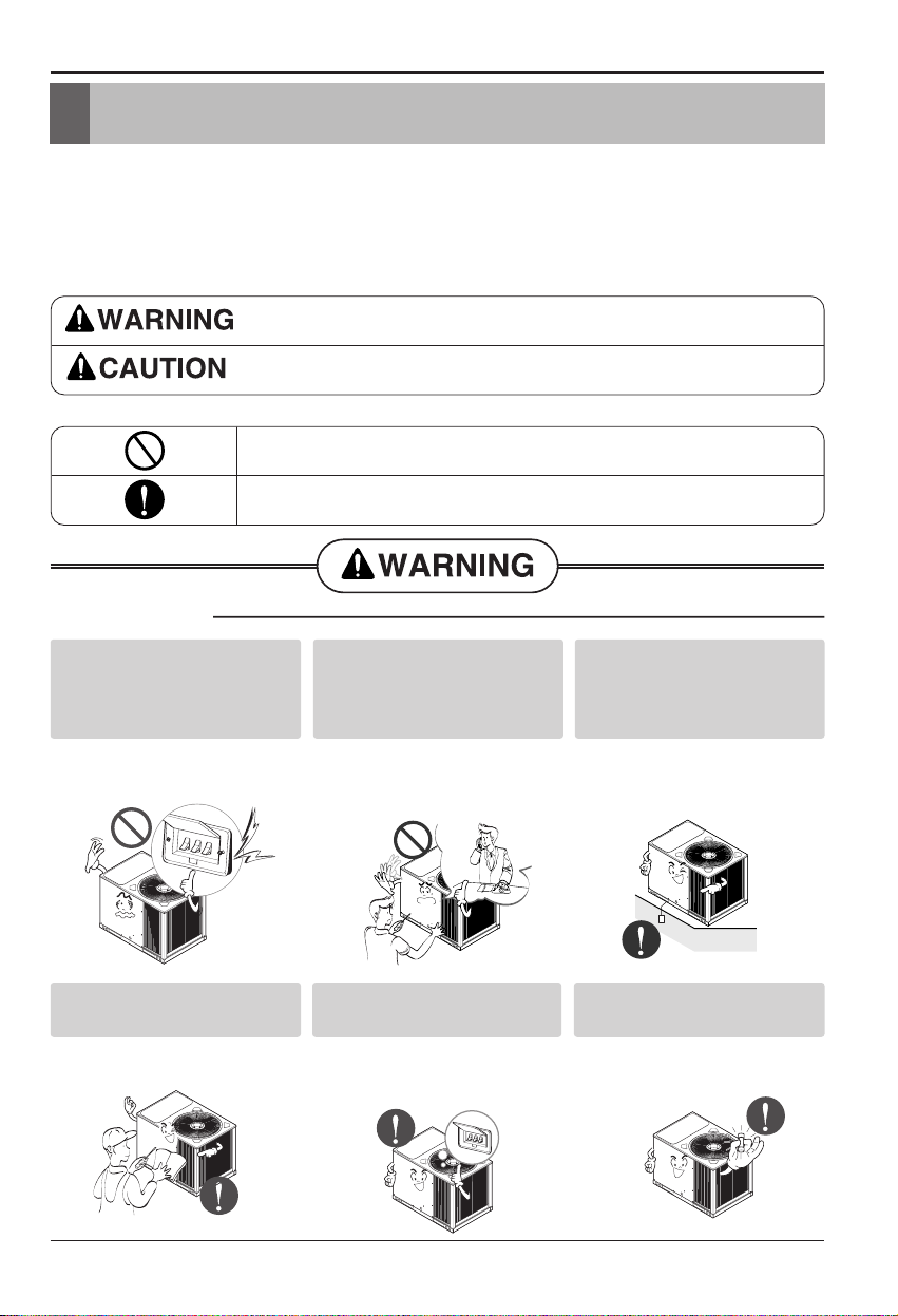
Ventilate the product from time to time when
operating it together with a stove, etc.
• There is risk of fire or electric shock.
Turn the main power off when cleaning or
maintaining the product.
• There is risk of electric shock.
Do not allow water to run
into electric parts.
• It may cause There is risk
of fire, failure of the product,
or electric shock.
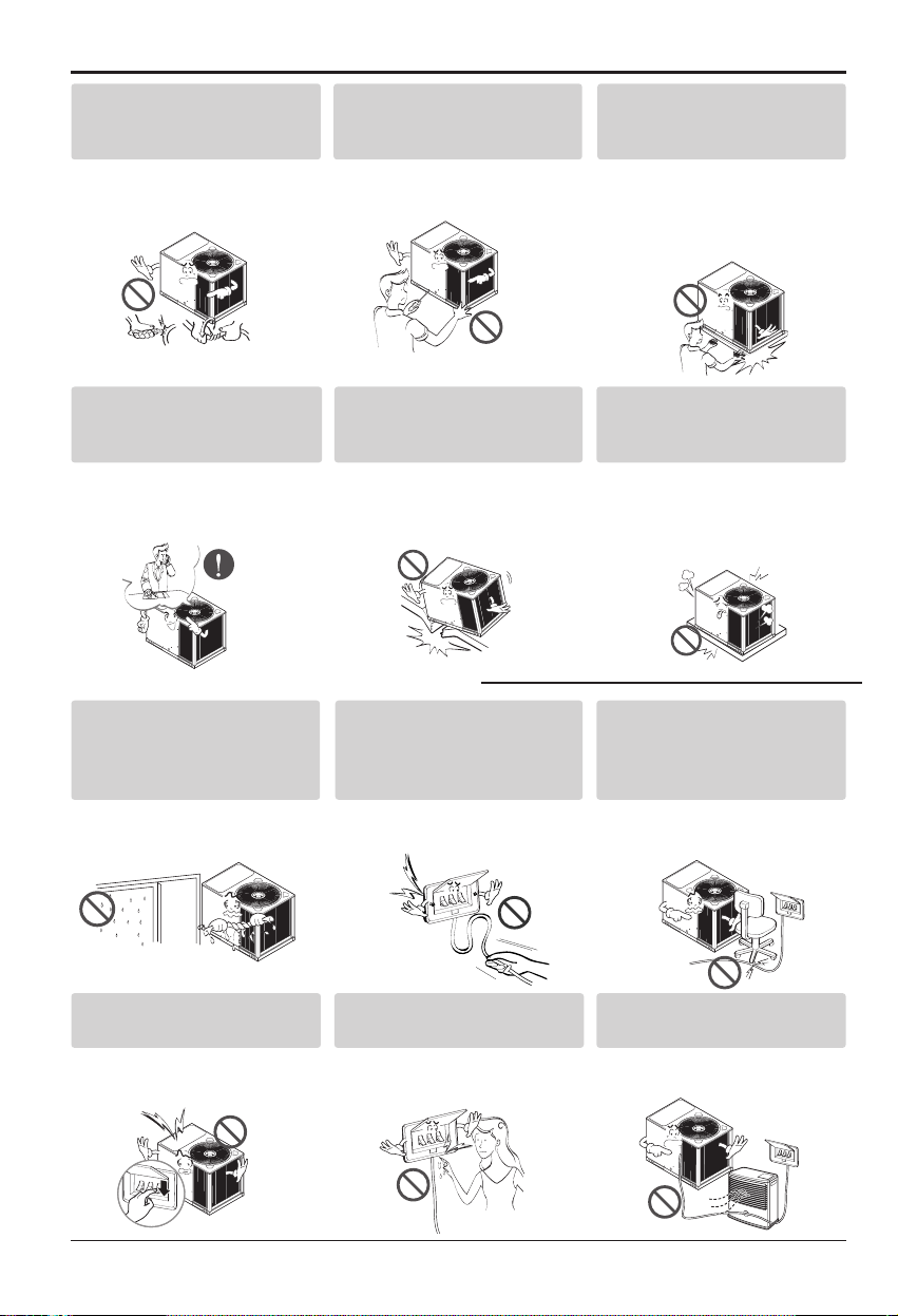
Do not store or use flammable
gas or combustibles near the
product.
• There is risk of fire or failure
of product.
Do not use the product in a
tightly closed space for a
long time.
• Oxygen deficiency could
occur.
When flammable gas leaks,
turn off the gas and open a
window for ventilation
before turn the product on.
•
Do not use the telephone or
turn switches on or off.
There
is risk of explosion or fire
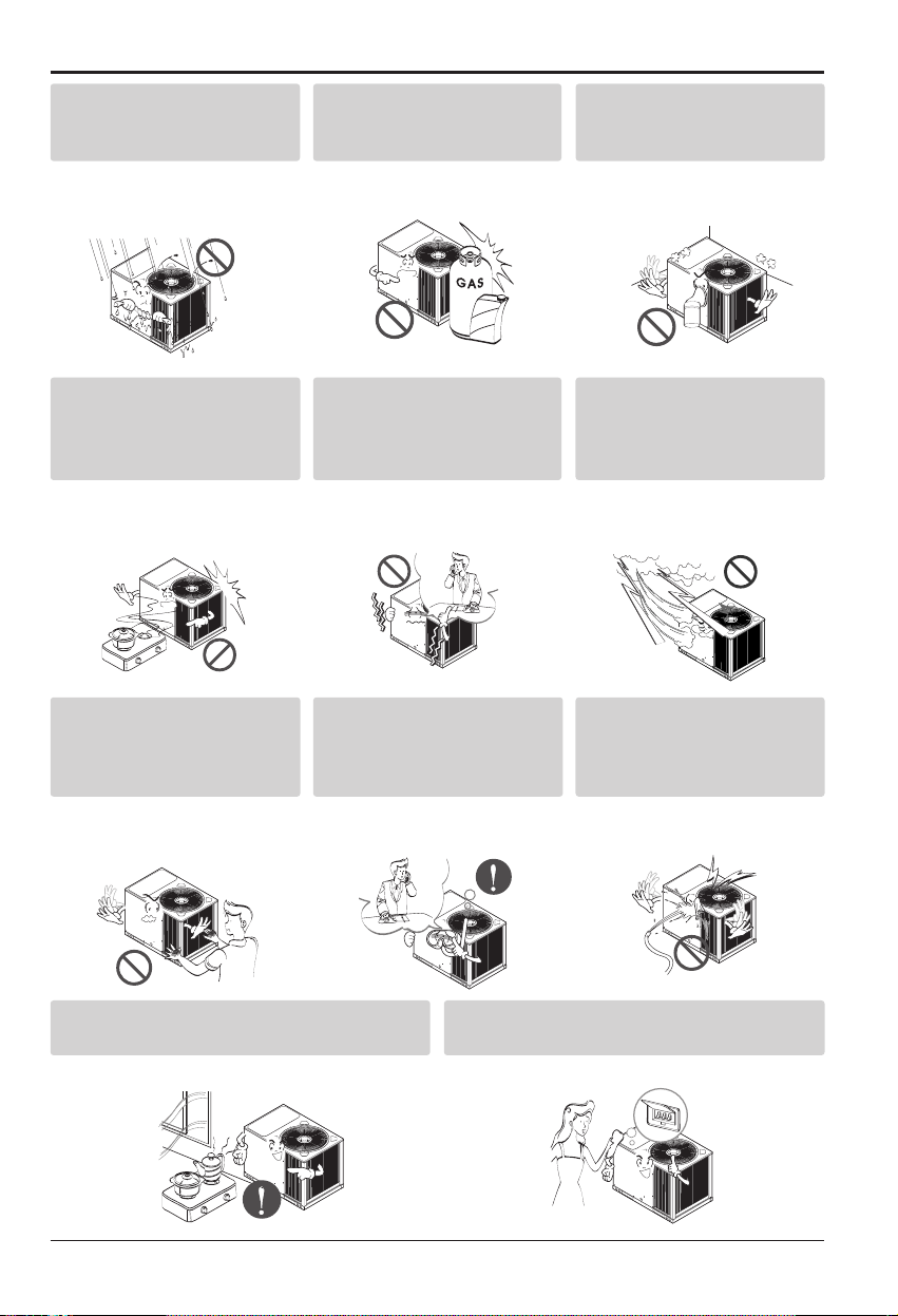
If strange sounds, or small or
smoke comes from product. Turn
the breaker off or disconnect the
power supply cable.
• There is risk of electric
shock or fire.
Stop operation and close the window
in storm or hurricane. If possible,
remove the product from the window
before the hurricane arrives.
• There is risk of property
damage, failure of product,
or electric shock.
Do not open the panel of the
product during operation. (Do
not touch the electrostatic filter,
if the unit is so equipped.)
• There is risk of physical
injury, electric shock, or
product failure.
When the product is soaked
(flooded or submerged),
contact an Authorized
Service Center.
• There is risk of fire or
electric shock.
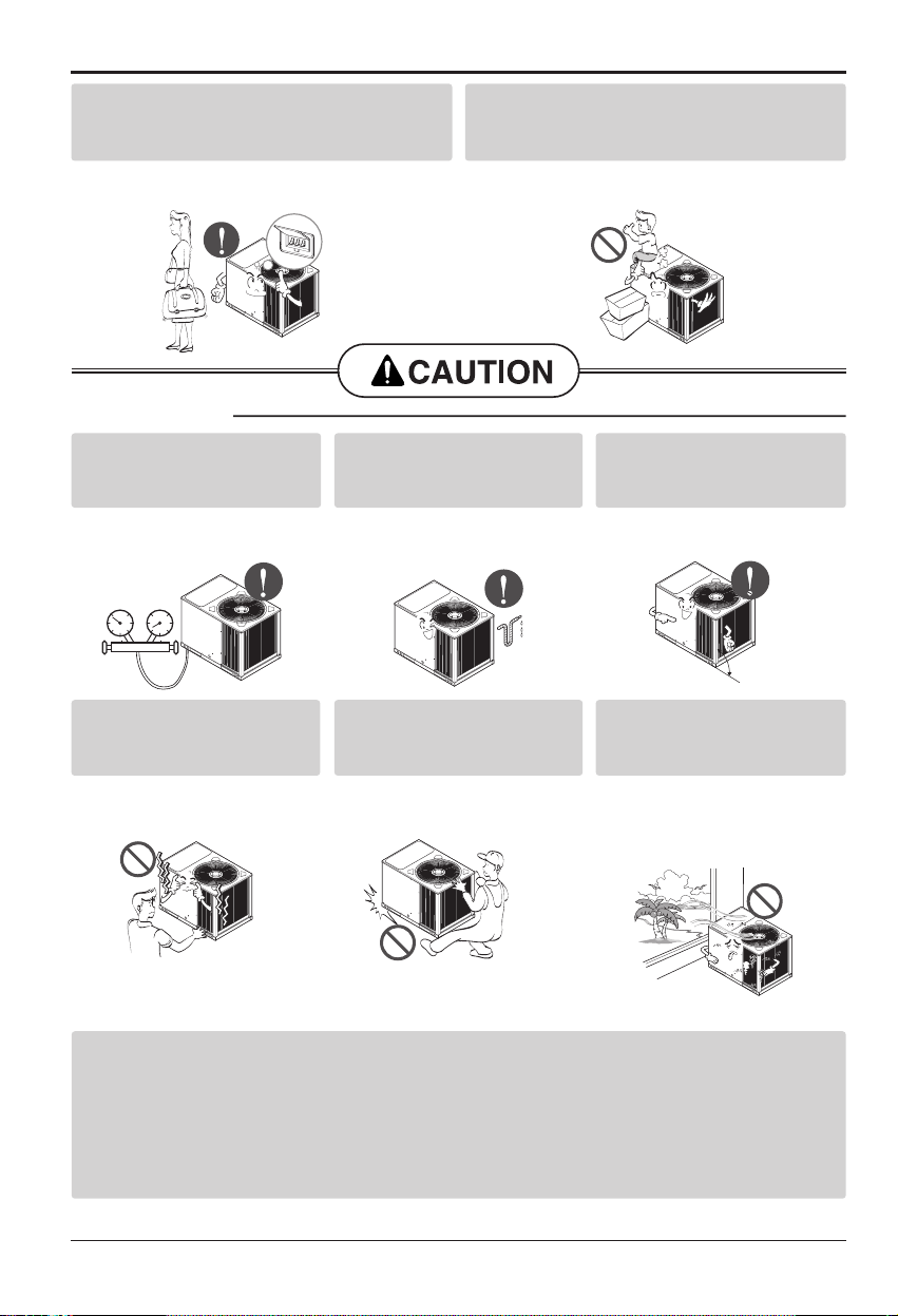
Be cautious that water
could not enter the product.
• There is risk of fire, electric
shock, or product damage.
Gasolin

6Single Package Type Air Conditioner
Safety Precautions
■Installation
Always check for gas
(refrigerant) pressure after
installation or repair of product.
• Low refrigerant levels may
cause failure of product.
Install the drain hose to
ensure that water is drained
away properly.
• A bad connection may
cause water leakage.
Keep level even when
installing the product.
• To avoid vibration or water
leakage.
Do not install the product where the
noise or hot air from the outdoor unit
could damage the neighborhoods.
• It may cause a problem for
your neighbors.
Don't use people to lift and
transport the product.
• Avoid personal injury.
Do not install the product
where it will be exposed to sea
wind (salt spray) directly.
•
It may cause corrosion on the product.
Corrosion, particularly on the condenser
and evaporator fins, could cause product
malfunction or inefficient operation.
When the product is not be used for a long
time, disconnect the power supply plug or
turn off the breaker.
• There is risk of product damage or failure, or
unintended operation.
Take care to ensure that nobody could step
on or fall onto the unit.
• This could result in personal injury and
product damage.
90°
Having perfect vacuum process in the factory, our units don't have drier but have filter in the
refrigerant circuit.
In case of recharging R-22 gas in the field,
"DRIER" must be installed on the liquid line which is connected from discharge part of
condenser to intake part of evaporator. Because the refrigerant circuit is capable of containing
water with imperfect vacuum.

Safety Precautions
Installation Manual 7
■Operation
Do not expose the skin directly to cool air for
long periods of time. (Don't sit in the draft.)
•This could harm to
your health.
Do not use the product for special purposes, such as
preserving foods, works of art, etc. It is a consumer air
conditioner, not a precision refrigeration system.
•There is risk of
damage or loss
of property.
Do not block the inlet or outlet of air flow.
•It may cause product failure.
Use a soft cloth to clean. Do not use harsh
detergents, solvents, etc.
•There is risk of fire, electric shock, or
damage to the plastic parts of the product.
Do not step on or put anything on the
product. (outdoor units)
•There is risk of personal injury and failure of
product.
Do not insert hands or other objects through the
air inlet or outlet while the product is operated.
•There are sharp and moving parts that could
cause personal injury.
Wax
Thinner
Do not drink the water drained from the
product.
•It is not sanitary and could cause serious
health issues.
Use a firm stool or ladder when cleaning or
maintaining the product.
•Be careful and avoid personal injury.

8Single Package Type Air Conditioner
Introduction
Air outlet vents
Control access
panel
Air intake vents
Return
Supply
(Side)
(Rear)
Control Power
Wiring
Unit Power Wires
This symbol alerts you to the risk of electric shock.
This symbol alerts you to hazards that could cause harm to the
air conditioner.
This symbol indicates special notes.
NOTICE
Introduction
Symbols Used in this Manual
Features
Front View
Rear View

Installation Manual 9
Dimensional Data
Dimensional Data
Single packaged cooling unit are designed for outdoor mounting with vertical condenser discharge. They can
be located either at ground level or on roof.
Each unit contains an operating charge of Refrigerant 22 as shipped.
Unit Dimensions(Figure 1A)
E
Center line of hole
A
B
CLEARANCE 34" CLEARANCE 18"
(HORIZONTAL)
CLEARANCE 34"
1.5" Dia. hole power wires
1.5" Dia. hole other purpose
CLEARANCE 48"
D
C
572
100
255
Unit : Inch(mm)
Horizontal Application Unit(Figure 1B)
Rear view showing duct opening for horizontal air flow.
A
G
BC D
E
H
SUPPLY
RETURN
F
Unit : Inch(mm)
A28
9/16 (725)
B32
11/16 (830)
C43
3/8 (1102)
D20
11/16 (525)
E2
7/8(73)
A13
3/16 (335)
B1
1/2(38)
C9
1/2(242)
D3/4(19)
E5
5/8(143)
F24
1/4(622)
G11
9/16 (294)
H9
1/16 (230)

10 Single Package Type Air Conditioner
Installation of Unit
Inspection
1) Check for damage after unit is unloaded. Report promptly, to the carrier, any damage found to unit. Do not drop unit.
2) Check the unit nameplate to determine if the unit voltage is correct for the application. Determine if adequate
electrical power is available. Refer to the application specifications.
3) Check to be sure the refrigerant charge has been retained during shipment. Access to 1/4" flare pressure taps may
be gained by removing compressor compartment access panel.
1) Unit Support
If unit is to be roof mounted check building codes for weight distribution requirements.
2) Location and Clearances
Installation of unit should conform to local building codes and the National Electrical Code.
Select a location that will permit unobstructed airflow into the condenser coil and away from the fan discharge and
permit unobstructed service access into the compressor compartment. Suggested airflow clearances and service
clearances are given in Figure 1.
3) Placing and Rigging
Rig the unit using either belt or cable slings. The sling eyelet must be placed through the lifting holes in the base rail
of the unit. The point where the slings meet the lifting eyelet should be at least 6 feet above the unit. Use spreader
bars to prevent excessive pressure on the top of the unit during lifting.
: The use of "spreader bars" is required when hoisting the unit (prevents damage to sides and top). Top
crating can be used as spreader bars.
4) Roof Mounted Units
On new roofs, the curb should be welded directly to the roof deck. For existing construction, nailers must be installed
under the curb if welding is not possible. Be sure attach the downflow ductwork to the curb before setting unit in
place.
When installing the unit, it must be level to insure proper condensate flow from the unit drain pan.
NOTICE
Figure 2
Location and Recommendations
Lifting beam
Cable or chain
Clevis
Spreader bar
Holes in base rail

Installation Manual 11
Installation of Unit
1. Ductwork construction guidelines
Connections to the unit should be made with three-inch canvas connectors to minimize noise and vibration
transmission.
Elbows with turning vanes or splitters are recommended to minimize air noise and resistance.
The first elbow in the ductwork leaving the unit should be no closer than three times blower diameter to
avoid turbulence and back pressure.
2. Attaching Horizontal Ductwork to the Unit
All conditioned air ductwork should be insulated to minimize heating and cooling duct losses. Use minimum
of 2" of insulation with a vapor barrier. The outside ductwork must be weather proofed between the unit
and the building.
When attaching ductwork to a horizontal unit, provide a flexible water tight connection to prevent noise
transmission from the unit to the ducts. The flexible connection must be indoors and molded out of heavy
canvas.
: Do not draw the canvas taut between the solid ducts.
NOTICE
Ductwork
A 3/4 inch male condensate drain connection is located on the corner of the unit next to the evaporator
section access panel. A trap should be installed and filled with water before starting the unit to avoid air
from being drawn through. Follow local codes and standard piping practices when running the drain line.
Pitch the line downward, away from the unit, and avoid long horizontal runs. See Figure 3.
Do not use reducing fittings in the drain lines.
The condensate drain must be:
1. Made of 3/4" pipe size.
2. Pitched 1/4" per foot to provide free drainage to convenient drain system.
3. Trapped
4. Must not be connected to closed drain system.
Condensate Drain Piping
Cleanout
Plug
Static pressure
Drain Pan
3/4 Inch Male
Panel Enclosure
1.5 Inches1.5 Inches
Attention
Be careful to not to have any double "U" trap as it may cause the drain water to leak.
Figure 3

12 Single Package Type Air Conditioner
This Unit Filters are anti-bacteria and washable type.
Access to the filters is made by removing the evaporator fan access panel. Each unit ships with free filters,
as determined by unit size.
On the filter access panel, "FILTER ACCESS PANEL" label is attatched.
: Do not operate unit without filters in place.
NOTICE
Installation of Unit
Filter Installation
Electrical Wiring
Figure 4
Attention
To increase compressor reliability, it is
recommended to attach defrosting
sensor(accessory) on the evaporator.
Contact LG agent for purchasing the
sensor.
Comply with Fig. A for detail
attachment and see Wiring diagram in
detail wiring.
Attach Defrost sensor
on this point
Check the unit nameplate for the required supply voltage. Determine if adequate electrical
power is available. Refer to application specifications.
Electrical wiring and grounding must be installed in accordance with local codes and with
the National Electric code Latest Revision.
It is important that proper electrical power is available for the unit. Voltage variation should
remain within the limits stamped on the nameplate.
Provide an approved weatherproof disconnect either on the side of unit or within close
proximity.
The branch circuit feeding the unit must be protected as shown on the unit rating plate.
The power supply lines must be run in approved conduit to the disconnect, and in the
bottom of the unit control box. Provide strain relief for all conduit with suitable connectors.
Provide flexible conduit supports whenever vibration transmission may cause a noise
problem within the building structure.
Electrical Power
Disconnect Switch
Over Current Protection
Power Wiring

Installation Manual 13
Installation of Unit
•Since the room temperature sensor is in the remote controller, the remote controller box
should be installed in a place away from direct sunlight, high humidity and direct supply of cold
air to maintain proper space temperature.
Install the remote controller about 5ft(1.5m) above the floor in an area with good air circulation
at an average temperature.
Do not install the remote controller where it can be affected by:
- Drafts, or dead spots behind doors and in corners.
- Hot or cold air from ducts.
- Radiant heat from sun or appliances.
- Concealed pipes and chimneys.
- Uncontrolled areas such as an outside wall behind the remote controller.
- This remote controller is equipped with a seven segment LED. display. For proper display of
the remote controller LED's, the remote controller should be installed properly as shown in
Fig.5.
(The standard height is 1.2~1.5 m from floor level.)
Operationunit
ZONE
1234
Humidify
JET
AUTO
AUTOSWING OPERATION
FANSPEED
Programset
SUBFUNCTION
SETTEMP
RoomTemp
HI
MED
LO
Heater
Defrost
Filter
Preheat
Outdoor
Time
Timer
On
Setno. Time
Off
01 03 05 07 09 11 13 15 17 19 21 23
Operationunit
ZONE
1234
Humidify
JET
AUTO
AUTOSWINGOPERATION
FANSPEED
Programset
SUBFUNCTION
SETTEMP
RoomTemp
HI
MED
LO
Heater
Defrost
Filter
Preheat
Outdoor
Time
Timer
On
Setno.Time
Off
010305070
9111315171
92
123
5feet
(1.5meters)
no
no
no
yes
Operationunit
ZONE
1234
Humidify
JET
AUTO
AUTOSWING OPERATION
FANSPEED
Programset
SUBFUNCTION
SETTEMP
RoomTemp
HI
MED
LO
Heater
Defrost
Filter
Preheat
Outdoor
Time
Timer
On
Setno. Time
Off
01 03 05 07 09 11 13 15 17 19 21 23
WIRED REMOTE CONTROLLER INSTALLATION
Figure 5 Typical locations for remote controller

14 Single Package Type Air Conditioner
Check the unit nameplate for the required supply voltage. Determine if adequate electrical power
is available. Refer to application specifications.
Electrical wiring and grounding must be installed in accordance with local codes and with the
National Electric code Latest Revision.
It is important that proper electrical power is available for the unit. Voltage variation should
remain within the limits stamped on the nameplate.
Provide an approved weatherproof disconnect either on the side of unit or within close proximity.
The branch circuit feeding the unit must be protected as shown on the unit rating plate.
The power supply lines must be run in approved conduit to the disconnect, and in the unit
control box. Provide strain relief for all conduit with suitable connectors. Provide flexible conduit
supports whenever vibration transmission may cause a noise problem within the building
structure.
: Holes are provided for low-voltage and high-voltage wiring. It is not necessary to punch
any new holes in either the interior or exterior unit panels. If new holes are punched,
performance will be adversely affected unless they are resealed to be both air- and
watertight.
NOTICE
Electrical Power
Disconnect Switch
Over Current Protection
Power Wiring
Power Entry Guide
Installation of Unit

Installation Manual 15
Installation of Unit
Important: Holes are provided for low-voltage and high-voltage wiring. It is not
necessary to punch any new holes in either the interior or exterior unit
panels. If new holes are punched, performance will be adversely affected
unless they are resealed to be both air- and watertight.
Typical Field Wiring Diagram (Figure 4)
(For single phase electricity product)
•See wiring diagram for details.
Note : For branch circuit wiring(main power supply to unit disconnect), Wire size for the
length of run should be determined using the circuit ampacity found on the unit
nameplate and the N.E.C..
GROUNDING : THE UNIT MUST BE ELECTRICALLY GROUNDED IN ACCORDANCE WITH
LOCAL CODES AND THE NATIONAL ELECTRICAL CODE.
(Note)
•Keep all wires away from the refrigerant pipe.
•Following diagram is the example of wiring arrangement.
1
2
3
4
R
G
Y
W
Live
Fan
Comp
Heater
5
6
HIGH VOLTAGE
TERMINAL BLOCK
FIELD WIRING
NOTE
FACTORY WIRING
LOW VOLTAGE
TERMINAL BLOCK
SEE NAMEPLATE FOR
LINE VOLTAGE AND
MAX FUSE SIZE
3Ø380/415V, 50Hz
POWER SUPPLY
RS T N
THERMOSTAT
1
2
3
4
R
G
Y
W
Live
Fan
Comp
Heater
5
6
HIGH VOLTAGE
MAGNETIC CONTACTOR
FIELD WIRING
NOTE
FACTORY WIRING
LOW VOLTAGE
TERMINAL BLOCK
SEE NAMEPLATE FOR
LINE VOLTAGE AND
MAX FUSE SIZE
1Ø208~230V, 60Hz
POWER SUPPLY
THERMOSTAT
L
1
2
3
R
G
Y
W
Live
Fan
Comp
Heater
4
N
HIGH VOLTAGE
MAGNETIC CONTACTOR
FIELD WIRING
NOTE
FACTORY WIRING
LOW VOLTAGE
TERMINAL BLOCK
SEE NAMEPLATE FOR
LINE VOLTAGE AND
MAX FUSE SIZE
3Ø208~230V, 60Hz
POWER SUPPLY
THERMOSTAT
Power Entry Guide
Power wires
Control wires

16 Single Package Type Air Conditioner
Installation of Unit
Start-Up Pre-Start Quick Check List
The "initialization" by the MAIN CONTROLLER occurs each time the system is powered-up. the
MAIN CONTROLLER performs internal self-diagnostics checks, which include identifying the
equipment components of its system, and the configuring of itself to that system. It also checks
itself to be sure it is functioning correctly.
•Is unit level and located with proper clearances?
•Is the duct work correctly sized, run, taped, insulated and
weather proofed with proper unit arrangement?
•Is condensate line properly sized, run trapped and pitched?
•Is the filter of the correct size, clean and in place?
•Is the wiring properly sized and run in according to the unit
wiring diagram?
•Are all wiring connections tight including those in unit and
compressor electrical boxes?
•Has the unit been properly grounded and fused with the
recommended fuse size?
•Is the remote controller correctly wired and in a good
location?
•Have the air conditioning systems been checked at the
service ports for charge and leak tested if necessary?
•Does the condenser fan and indoor fan turn freely without
rubbing and are they tight on the shafts?
•Visually inspect the unit to ensure that the airflow required
for the condenser coil is not obstructed from the unit.
•Inspect the control panel wiring to verify that all electrical
connections are tight, and that wire insulation is intact.
•Is the indoor fan and rotation correct?
•Has the indoor fan speed been determined and the proper
speed been set?
•Has all work been done in accordance with applicable local
and national codes?
•Are all covers and access panels in place to prevent air
loss and safety hazards?
➔See Figure 1.
➔See duct work
installation
➔See air flow
performance data
Power-up Initialization
WARNING:
Bodily injury can result from high voltage electrical
components. If operating checks must be performed with the unit
operating, it is the technician's responsibility to recognize these hazards
and proceed safely. Failure to do so could result in severe personal
injury or death due to electrical shock or contact with moving parts.

Installation Manual 17
Installation of Unit
Starting the Unit
(If unit is equipped with electric heater.)
Check to ensure all grilles and registers are open and all unit access doors are closed before
start-up.
Turn on unit main power supply.
Press the E/Heater operation button on the Remote controller.
Set the temperature approximately 5˚C above room temperature.
Verify that the unit airflow rate is adjusted according to information provided in "Determining
Evaporator Fan Adjustment" section of this manual.
To start the unit in the cooling mode, close unit disconnect switch and set the operating mode to
COOL and move the cooling setpoint approximately 5˚C below room temperature. The
condenser fan motor, compressor and evaporator fan motor should operate automatically. There
will be a delay of up to 3 minutes before the unit will start in the cooling mode.
After the unit has operated in the cooling mode for a short period of time, install pressure
gauges on the gauge ports of the discharge and suction line valves.
: Always route refrigerant hoses through the port hole provided and have compressor
access panel in place.
Check the suction and discharge pressures and compare them to the normal operating
pressures provided in the unit's Service Manual.
: Do not use pressures from Service manual to determine the unit refrigerant charge. The
correct charge is shown on the unit nameplate. To charge the system accurately, use
superheat charging or weigh the charge.
With the compressor operating, check the line voltage at the unit. The voltage should be within
the range shown on the unit nameplate. If low voltage is encountered, check the size and length
of the supply line from the main disconnect to the unit. The line may be undersized for the length
of the run.
NOTICE
NOTICE
Operating Pressures
Heating Mode
Cooling Mode
Voltage
WARNING: Bodily injury can result from high voltage electrical
components. If operating checks must be performed with the unit
operating, it is the technician's responsibility to recognize these
hazards and proceed safely. Failure to do so could result in severe
personal injury or death due to electrical shock or contact with moving
parts.

18 Single Package Type Air Conditioner
Installation of Unit
Final Installation Checklist and Maintenance
You can do some of the periodic maintenance functions for your unit yourself; this includes
cleaning air filters, cleaning unit cabinet, cleaning the condenser coil, and conducting a general
unit inspection on a regular basis.
It is very important to keep the central duct system air filters clean. Be sure to inspect them at
least once each month when the system is in constant operation. (In new buildings, check the
filters every week for the first 4 weeks.)
These units have anti-fungus filter.
Permanent type filters can be cleaned by washing with a mild detergent and water. Ensure that
the filters are thoroughly dry before reinstalling them in the unit (or duct system).
•Does unit run and operate as described in the "Sequence of Operation" in the unit
Service Manual?
•Is the condenser fan and indoor blower operating correctly, with proper rotation and
without undue noise?
•Are the compressors operating correctly and has the system been checked with a
charging chart?
•Have voltage and running currents been checked to determine if it is within limits?
•Have the air discharge grilles been adjusted to balance the system?
•Has the ductwork been checked for air leaks and condensation?
•Has the indoor airflow been checked and adjusted if necessary?
•Has the unit been checked for tubing and sheet metal rattles and are there unusual
noises to be checked?
•Are all covers and panels in place and properly fastened?
•Has the owner or maintenance personnel been given this manual, warranty, and been
instructed on proper operation and maintenance?
Routine Maintenance By Owner
Air Filters
WARNING: Before removing access panels to service unit, disconnect
power supply. Failure to disconnect power before attempting any
servicing can result in severe injury or death.

Installation Manual 19
Installation of Unit
Unfiltered air circulates through the unit's condenser coil and can cause the coil's surface to
become clogged with dust, dirt, etc.. To clean the coil, vertically (i.e., along the fins) stroke the
coil surface with a soft bristled brush.
Keep all vegetation away from the condenser coil area.
To keep your unit operating safely and efficiently, the manufacturer recommends that a qualified
serviceman check the entire system at least once each year, or more frequently if conditions
warrant. Your serviceman may examine these areas of your unit:
Complete the unit inspections and service routines described below at the beginning of each
heating season.
Inspect the control panel wiring to verify that all electrical connections are tight and wire
insulation is intact.
Condenser coil
Maintenance Performed by Serviceman-Cooling Season
Maintenance Performed By Serviceman-Heating Season
1. Filters
2. Motors and drive system components
3. Condenser coils
4. Safety Controls
5. Electrical components and wiring
6. Condensate drain
7. Inspect the unit duct connections to ensure they are
physically sound and sealed to the unit casing.
8. Inspect the unit mounting support to see that it is
sound.
9. Inspect the unit to ensure there is no obvious
deterioration.
➔For cleaning
➔For cleaning
➔For mechanical cleaning
➔For possible replacement or
connection tightness
➔For cleaning
CAUTION: To prevent injury or death due to electrical shock of contact
with moving parts, lock unit disconnect switch in open position before
servicing unit.
To prevent an explosion and possible injury, death and equipment
damage, do not store combustible materials, gasoline or other
flammable vapors and liquids near the unit.
Table of contents
Other LG Air Conditioner manuals
Popular Air Conditioner manuals by other brands

Daikin
Daikin RXYMQ36MVJU Operation manual

Carrier
Carrier R4A4S installation instructions

Lennox
Lennox XC17 Series Unit information

Friedrich
Friedrich MWM18Y3J Installation and operation manual

Mitsubishi Electric
Mitsubishi Electric MSZ-GL18NA installation guide

Daikin
Daikin FXLQ12MVJU installation manual