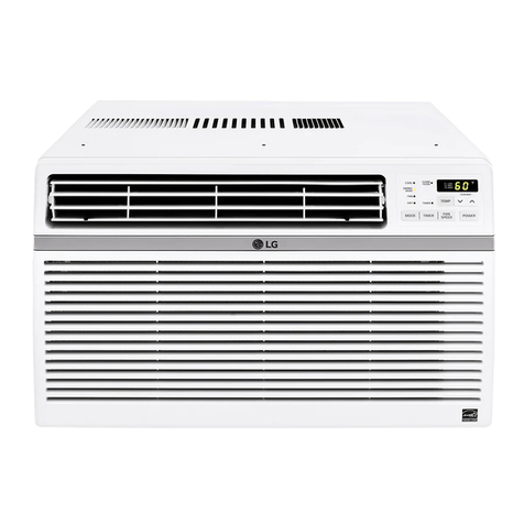
LG LT-D3680CL User manual

Contents
Functions .................................................................................................................................3
Product Specifications (Cooling & Heating)..........................................................................5
Dimensions ..............................................................................................................................7
Refrigeration Cycle Diagram ................................................................................................10
Wiring Diagram ......................................................................................................................12
Operation Details ...................................................................................................................15
Installation of Indoor, Outdoor Unit .....................................................................................18
3-way Valve ............................................................................................................................34
Cycle Troubleshooting Guide ...............................................................................................39
Electronic Parts Troubleshooting Guide .............................................................................40
Electronic Control Device .....................................................................................................43
Schematic Diagram ...............................................................................................................44
Exploded View and Replacement Parts List .......................................................................45
–2–

Functions
Indoor Unit
Operation ON/OFF by Remote controller
Sensing the Room Temperature
Room temperature control
Starting Current Control
Time Delay Safety Control
Indoor Fan Speed Control
Soft Dry Operation Mode
Airflow Direction Control
Auto Operation(Auto Change Over)
Deice (defrost) control (Heating)
Auto Restart
–3–
Hot-start Control (Heating) • The indoor fan stops until the evaporator piping tempera-
ture will be reached at 28°C.
Compact and light design • To install a unit is very convenient size because of smaller
than fextile size. ( 600 x 600 )
Low noise • The most advanced low-noise design.
• The adoption of turbo fan and round type heat exchanger
give the quietest operation.
Long life filter • Long life type(wrinkle) and wastable and anti-bacteria filter
is adopted.
Plasma Air Purifying Filter(2HL Only)
High head height Drain pump • Built-in drain pump automatically drains water.
• A standard drain-head height of up to 700mm is possible.
High-Ceilingcorresponding Function • According to the height of ceiling, the RPM of indoor fan
motor is selectable to increase air reaching distance.
Central Control(Optional) •
It is operating individually or totally by central control function.
Group Control(Optional Wiring) •
Each controller can control 16 units and 8 controllers can connect.
•
It operates maximum 16 units by only one wired remote con-
troller and each unit starts random to prevent overcurrent.
• Room temperature sensor. (Thermistor)
•
Maintains the room temperature in accordance with the Setting Temp.
• Indoor fan is delayed for 5 seconds at the starting.
• Restarting is inhibited for approx. 3 minutes.
• Jet, High, Med, Low
• Intermittent operation of fan at low speed.
• The louver can be set at swing up and down automatically.
• Although the air-conditioner is turned off by a power failure, it is restarted automati-
cally previous operation mode after power supply.
• The setting temperature and desired operation mode are auto-
matically set by fuzzy rule.
• Both the indoor and outdoor fan stops during defrosting.
• Hot start after defrost ends.

–4–
Remote Controller
Operation ON/OFF
Operation Mode Selection
Fan Speed Selection
Room Temperature Display
Temperature Setting
Setting the Timer
Weekly Program
(Cooling
model only) (Heating
model only)
(Low) (Med) (High)
Cooling Operation Mode ( )
Heating Operation Mode ( ) Auto Operation Mode ( )
Soft Dry Operation Mode ( )
Fan Operation Mode
HI JET AUTOMEDLO
Program Holiday
SET/CLR
MinHour
Week
Timer CancelTimer Cancel
: High:39°C ↔LOW:11°C
: Fan Operates without cooling & heating
Cooling Heating
Down to 18°C
Up to 30°CDown to 16°C
Up to 30°C

Model
3, 380-415, 50 3, 380-415, 50 3, 380-415, 50 3, 380-415, 50 3, 380-415, 50 3, 380-415, 50
9,073(10,550) 9,073(10,550) 9,073(10,550) 12,096(14,065) 12,096(14,065) 12,096(14,065)
36,000 36,000 36,000 48,000 48,000 48,000
- 9,073(10,550) 9,073(10,550) - 12,096(14,065) 12,096(14,065)
- 36,000 36,000 - 48,000 48,000
4,000 4,000 4,000 4,900 4,900 4,900
- 3,500 3,500 - 4,400 4,400
7.5 7.5 7.5 8.5 8.5 8.5
- 6.5 6.5 - 8 8
50 50 50 55 55 55
- 48 48 - 55 55
2.27 2.27 2.27 2.3 2.3 2.3
- 3.0 3.0 - 2.93 2.93
25 25 25 30 30 30
58 58 58 58 58 58
4.0 4.0 4.0 5.3 5.3 5.3
OOOOOO
XO O X O O
444444
OOOOOO
OOOOOO
OOOOOO
OOOOOO
OOOOOO
444444
OOOOOO
XO O X O O
OOOOOO
OOOOOO
OOOOOO
OOOOOO
Option Option Option Option Option Option
OOOOOO
XX O X X O
2,900 2,900 2,900 4,300 4,250 4,250
840*840*288 840*840*288 840*840*288 840*840*288 840*840*288 840*840*288
950*950*30 950*950*30 950*950*30 950*950*30 950*950*30 950*950*30
790*965*320 790*965*320 790*965*320 900*1225*370 900*1225*370 900*1225*370
32 32 32 32 32 32
78 78 78 95 95 95
14 : 4*2.5 14 : 4*2.5 14 : 4*2.5 12 : 4*3.5 12 : 4*3.5 12 : 4*3.5
18 : 4*0.75 18 : 5*0.75 18 : 5*0.75 16 : 4*1.25 16 : 5*1.25 16 : 5*1.25
3/8(9.52) 3/8(9.52) 3/8(9.52) 3/8(9.52) 3/8(9.52) 3/8(9.52)
5/8(15.88) 5/8(15.88) 5/8(15.88) 3/4(19.05) 3/4(19.05) 3/4(19.05)
50 50 50 50 50 50
30 30 30 30 30 30
FoamPE/5mm FoamPE/5mm FoamPE/5mm FoamPE/5mm FoamPE/5mm FoamPE/5mm
Ø25 / 32 Ø25 / 32 Ø25 / 32 Ø25 / 32 Ø25 / 32 Ø25 / 32
LT-D3680CL LT-D3680HL LT-D3682HL LT-D4880CL LT-D4880HL LT-D4882HL
Power Supply ø, V, Hz
Capacity Cooling kcal/h(W)
Btu/h
Heating kcal/h(W)
Btu/h
Input Cooling W
Heating W
Running Current Cooling A
Heating A
Starting Current Cooling A
Heating A
E.E.R kcal/h(W)
C.O.P W/W
Air Circulation Indoor m3/min
Outdoor m3/min
Moisture Removal l/ h
Air-Flow Direction Control
Heating Operation Mode
Fan Speeds (steps)
Auto Operation (Changeover)
Forced Operation
Jet Cool
Soft Dry Operation
Timer Delay Safety Function
Feature Air Deflection (Way)
Self Diagnosis
Hot start
Auto Restart
Air refresh (Hole)
High Ceiling
Group Control (Optional wiring)
Central Control
Wired remote controller (with weekly Program)
Plasma A/Cleaner
Refrigerant(R-22) Charge g
Dimensions Indoor mm
(W x D x H) Panel mm
Outdoor mm
Net Weight Indoor kg
Outdoor kg
Main Power Cord AWG#:P*mm2
Connection Cable AWG#:P*mm2
Service Valve Liquid (inch)
Gas (inch)
Installation Pipe Length (m)
Elevation (m)
Insulation(material/thickness)
Drain Hose(I.D/O.D) mm
Product Specifications (Cooling & Heating)
–5–

–6–
Power Supply ø, V, Hz
Capacity Cooling kcal/h(W)
Btu/h
Heating kcal/h(W)
Btu/h
Input Cooling W
Heating W
Running Current Cooling A
Heating A
Starting Current Cooling A
Heating A
E.E.R kcal/h(W)
C.O.P W/W
Air Circulation Indoor m3/min
Outdoor m3/min
Moisture Removal l/ h
Air-Flow Direction Control
Heating Operation Mode
Fan Speeds (steps)
Auto Operation (Changeover)
Forced Operation
Jet Cool
Soft Dry Operation
Timer Delay Safety Function
Feature Air Deflection (Way)
Self Diagnosis
Hot start
Auto Restart
Air refresh (Hole)
High Ceiling
Group Control (Optional wiring)
Central Control
Wired remote controller (with weekly Program)
Plasma A/Cleaner
Refrigerant(R-22) Charge g
Dimensions Indoor mm
(W x D x H) Panel mm
Outdoor mm
Net Weight Indoor kg
Outdoor kg
Main Power Cord AWG#:P*mm2
Connection Cable AWG#:P*mm2
Service Valve Liquid (inch)
Gas (inch)
Installation Pipe Length (m)
Elevation (m)
Insulation(material/thickness)
Drain Hose(I.D/O.D) mm
1, 220, 60 1, 220, 60
12,096(14,065) 12,096(14,065)
48,000 48,000
- 12,096(14,065)
- 48,000
5,000 5,000
- 4,500
24 24
- 22.5
55 55
-55
2.3 2.3
- 2.93
30 30
58 58
5.3 5.3
OO
XO
44
OO
OO
OO
OO
OO
44
OO
XO
OO
OO
OO
OO
Option Option
OO
XX
4,300 4,300
840*840*288 840*840*288
950*950*30 950*950*30
900*1225*370 900*1225*370
32 32
95 95
10 : 3*6.0 10 : 3*6.0
16 : 4*1.25 16 : 5*1.25
3/8(9.52) 3/8(9.52)
3/4(19.05) 3/4(19.05)
50 50
30 30
FoamPE/5mm FoamPE/5mm
Ø25 / 32 Ø25 / 32
Model
LT-D4820CL LT-D4820HL

Dimensions
–7–
290
950
950
950
950
290
210.5
180
52
140
40
110
30
90
90
110
55
840
785
840
678
(1) Indoor Unit

(2) Outdoor Unit(36K)
–8–
L6L7 L8 L9
L4
H
L11
L10
L5
W
D
L1
L2
L3
Gas side
3-way valve
Liquid side
3-way valve
MODEL
DIM
W mm 790
H mm 965
D mm 320
L1 mm 358
L2 mm 19
L3 mm 339
L4 mm 920
L5 mm 38
L6 mm 503
L7 mm 144
L8 mm 143
L9 mm 73
L10 mm 93
L11 mm 80
36K Models

–9–
(3) Outdoor Unit(48K)
L6L7 L8 L9
L4
H
L11
L10
L5
W
D
L1
L2
L3
Gas side
3-way valve
Liquid side
3-way valve
MODEL
DIM
W mm 900
H mm 1,225
D mm 370
L1 mm 460
L2 mm 45
L3 mm 410
L4 mm 1,135
L5 mm 90
L6 mm 550
L7 mm 175
L8 mm 175
L9 mm 112
L10 mm 120
L11 mm 83
48K Models

Refrigeration Cycle Diagram
• HEAT PUMP
(LT-D3680HL, LT-D3682HL, LT-D4880HL, LT-D4882HL, LT-D4820HL)
•Rated performance for refrigerant line length of: 7.5m
•If 48K Capacity is installed at a distance of 15m, 450g of refrigerant
should be added ....................................................(15-7.5) x 60g
–10–
INDOOR UNIT OUTDOOR UNIT
HEAT
EXCHANGER HEAT
EXCHANGER
COMPRESSOR
GAS SIDE
LIQUID SIDE
COOLING
HEATING
REVERSING
VALVE
CAPILLARY TUBE
Capacity
36K 5/8" 3/8"
7.
550
48K 3/4" 3/8"
7.
550
GAS LIQUID
530 50
530 60
Elevation (m)
Length (m) * Additional
refrigerant
(g/m)
Pipe Size
(Diameter:ø)
Rated RatedMax. Max.

–11–
• COOLING ONLY(LT-D3680CL, LT-D4880CL, LT-D4820CL)
•Rated performance for refrigerant line length of: 7.5m
•If 48K Capacity is installed at a distance of 15m, 450g of refrigerant
should be added ....................................................(15-7.5) x 60g
INDOOR UNIT OUTDOOR UNIT
HEAT
EXCHANGER
(CONDENSER)
HEAT
EXCHANGER
(CONDENSER)
COMPRESSOR
GAS SIDE
LIQUID SIDE
CAPILLARY TUBE
Capacity
36K 5/8" 3/8"
7.
550
48K 3/4" 3/8"
7.
550
GAS LIQUID
530 50
530 60
Elevation (m)
Length (m) * Additional
refrigerant
(g/m)
Pipe Size
Rated Rated
Max. Max.

–12–
Wiring Diagram
(1) Capacity: 48K(3ø) - LT-D4882HL, LT-D4880HL, LT-D4880CL
<HEAT PUMP>
<COOLING ONLY>
OUTDOOR WIRING DIAGRAM INDOOR WIRING DIAGRAM
INDOOR
MOTOR DRAIN
PUMP STEP
MOTOR
TEMP.
THERMISTOR
PIPE
THERMISTOR
REMOTE
CONTROL
FLOAT S/W
CN -DISP
DISPLAY PCB
ONLY LT-D xxx2HL
AIR
CLEANER
H.V. ASSY
DOOR S/W
TERMINAL
BLOCK
TO OUTDOOR UNIT
3854A20072G3854A20072H
BR
YL
BK
OR
BL
BL
BR
GN/YL
RD
BK
BL
GN
/
YL
COMP
RD
BK
WH
RD
BK
1 2 3 4 5
FUSE T3.15A
4 WAY
RTM
POWER SUPPLY
STN
BK
BK BKWH
WH WH
RD
OR
BK
63H2
WH
D.P CTH
TNS NO NC
WH
OR
BK 52F1
52C 1
2
3
4
5
6
31
T/B1
T/B2
32
B
A
FMo
49FMo FMo
49FMo
YL BK
OR
BK
T3 T2 T1
RD
WH
CM
12
34
56
78
YL BK
OR
BK
BK
BL
BL
WHWH
Co Co
20SV
GN/YL TMo
To the indoor unit
1(L)
2(N)
3
4
5
BK
WHWH YL
BK
RD
F1
F1
OUTDOOR WIRING DIAGRAM INDOOR WIRING DIAGRAM
INDOOR
MOTOR DRAIN
PUMP STEP
MOTOR
TEMP.
THERMISTOR
PIPE
THERMISTOR
REMOTE
CONTROL
FLOAT S/W
CN -DISP
DISPLAY PCB
ONLY LT-D xxx2CL
AIR
CLEANER
H.V. ASSY
DOOR S/W
TERMINAL
BLOCK
TO OUTDOOR UNIT
3854A20072P3854A20072Z
BR
YL
BK
OR
BL
BL
BR
GN/YL
RD
BL
GN
/
YL
COMP
BK
RD
WH
RD
BK
1 2 3 4 5
FUSE T3.15A
GN/YL TMo
To the indoor unit
2(N)
1(L)
3
4
5
F1
F1
RTM
POWER SUPPLY
STN
BK
BK
WH
RD
WH WH
52C 1
2
3
4
5
6
31
32
B
A
FMo
49FMo FMo
49FMo
BK
T3 T2 T1
RD
WH BK
BL
WH
WH
CM
YL BK
OR
Co Co
YL
OR BK
BR
BK
OR
OR
BR

–13–
(2) Capacity: 36K(3ø) - LT-D3680HL, LT-D3680CL, LT-D3682HL
<HEAT PUMP>
<COOLING ONLY>
OUTDOOR WIRING DIAGRAM INDOOR WIRING DIAGRAM
INDOOR
MOTOR DRAIN
PUMP STEP
MOTOR
TEMP.
THERMISTOR
PIPE
THERMISTOR
REMOTE
CONTROL
FLOAT S/W
CN -DISP
DISPLAY PCB
ONLY LT-D xxx2HL
AIR
CLEANER
H.V. ASSY
DOOR S/W
TERMINAL
BLOCK
TO OUTDOOR UNIT
3854A20072G3854A90021F
BR
YL
BK
OR
BL
BL
BR
GN/YL
RD
BK
BL
GN
/
YL
COMP
RD
BK
WH
RD
BK
1 2 3 4 5
FUSE T3.15A
4 WAY
78
1TM
380-415V
3Ø, 50Hz
POWER SUPPLY
BK
63H2
52C 13531
24632
B
A
BK
WH BK
52F1
12
34
56
TNS NO
C TH
NC
D.P
WH BK
WH
BK
WH
BL
RD
GN/YL
BLBK
WH
T/B1
F1
BK
WH
WH
RD
BK
WH BK
BK
RD
WH
T1 T3
T2
CH1
Co
OR YL Co
OR
FMo1FMo2CM
YL
YL
BKBK
BR
BK
BL
BK
WH
GN/YL TMo
To the indoor unit
WH
234
RSTN
20SV BK BK
BK BK
1
2
3
4
5
6
OUTDOOR WIRING DIAGRAM INDOOR WIRING DIAGRAM
INDOOR
MOTOR DRAIN
PUMP STEP
MOTOR
TEMP.
THERMISTOR
PIPE
THERMISTOR
REMOTE
CONTROL
FLOAT S/W
CN -DISP
DISPLAY PCB
ONLY LT-D xxx2CL
AIR
CLEANER
H.V. ASSY
DOOR S/W
TERMINAL
BLOCK
TO OUTDOOR UNIT
3854A20072P3854A90010Y
BR
YL
BK
OR
BL
BL
BR
GN/YL
RD
BL
GN
/
YL
COMP
BK
RD
WH
RD
BK
1 2 3 4 5
FUSE T3.15A
1TM
380-415V
3ø,50Hz
POWER SUPPLY
BK
52C 13531
24632
B
A
BK
WH
WH
BK
WH
BL
GN/YL
T/B
F1
BK
WH
RD
WH
BK
RD
WH
T1 T3
T2
Co
OR YL Co
OR
FMo1FMo2CM
YL
BKBK
BR BL
BK
BKBK
WH
GN/YL TMo
To the indoor unit
WH WH
234
RSTN
1
2
3
4
5
6

(3) Capacity: 48K(1ø) - LT-D4820HL, LT-D4820CL
<HEAT PUMP>
<COOLING ONLY>
–14–
OUTDOOR WIRING DIAGRAM INDOOR WIRING DIAGRAM
3854A20072G3854A20072X
INDOOR WIRING DIAGRAM
INDOOR
MOTOR DRAIN
PUMP STEP
MOTOR
TEMP.
THERMISTOR
PIPE
THERMISTOR
REMOTE
CONTROL
FLOAT S/W
CN -DISP
DISPLAY PCB
ONLY LT-D xxx2HL
AIR
CLEANER
H.V. ASSY
DOOR S/W
TERMINAL
BLOCK
TO OUTDOOR UNIT
BR
YL
BK
OR
BL
BL
BR
GN/YL
RD
BK
BL
GN
/
YL
COMP
RD
BK
WH
RD
BK
1 2 3 4 5
FUSE T3.15A
4 WAY
CM
1
2
3
4
5
6
1Ø,220V,60Hz
POWER SUPPLY
LN 1
2
3
2
5
2
31
32
B
A
WH
BR BR
RD
YL YL
YL
FMo1
49FMo FMo2
49FMo
Co
TM 52C
63H2
Co
BK YL BK
OR OR
RD
BK
BK RD
Cr
T2
T3 T1
WH
WH WH BK
BK
WH WH
WH
BL
YL
BK
WH
BL
RD
GN/YL
To the indoor unit
52F1
BL
WH
PTCR
GN/YL GN/YL Tmo
12
34
56
78
F1
T/B1
T/B2
RD
RD
20SV
BK
BK
BK
BR
OR
BK
D.P
TNS NO NC
C TH
WH
WH
OUTDOOR WIRING DIAGRAM INDOOR WIRING DIAGRAM
INDOOR
MOTOR DRAIN
PUMP STEP
MOTOR
TEMP.
THERMISTOR
PIPE
THERMISTOR
REMOTE
CONTROL
FLOAT S/W
CN -DISP
DISPLAY PCB
ONLY LT-D xxx2CL
AIR
CLEANER
H.V. ASSY
DOOR S/W
TERMINAL
BLOCK
TO OUTDOOR UNIT
3854A20072P3854A20072Y
BR
YL
BK
OR
BL
BL
BR
GN/YL
RD
BL
GN
/
YL
COMP
BK
RD
WH
RD
BK
1 2 3 4 5
FUSE T3.15A
CM
1
2
3
4
5
6
1Ø,220V,60Hz
POWER SUPPLY
LN 1
2
3
4
5
6
31
32
B
A
WH
BR BR
OR
BK
YL
FMo1
49FMo FMo2
49FMo
Co
TM 52C
Co
BK YL BK
OR OR
BK
BK RD
Cr
T2
T3 T1
WH
WH WH
BK BK
BK
BK
WH
BL
GN/YL
To the indoor unit
BL
WH
PTCR
GN/YL GN/YL Tmo
F1
BK
BK
BR
WH

–15–
Operation Details
(1) The function of main control
1. Time Delay Safety Control
•3min The compressor is ceased for 3minutes to balance the pressure in the refrigeration cycle.
(Protection of compressor)
•5sec
Vertical air flow direction control louvers open in 5 seconds to prevent noise between louvers and wind.
•30sec The 4-way valve is ceased for 30sec. to prevent the refrigerant-gas abnormal noise when the Heating
operation is OFF or switched to the other operation mode while compress is off.
While compressor is running, it takes 3~5 seconds to switch.
2. Auto Swing Control
•This function is to swing the louver up and down automatically.
3. Air-Filter Checking Control
•'Filter' will display in the remote controller display and main body display when an air-filter is polluted. Then clean
the air-filter for reference to Owners Manual.
4. Soft-Dry Operation
•The indoor fan speed is automatically set to the low, so the shift of the indoor fan speed is impossible because of
already being set to the best speed for Dry Operation by Micom Control.
5. Cooling Mode Operation
•When selecting the Cooling( ) Mode Operation, the unit will operate according to the setting by the remote con-
troller and the operation diagram is as following
Intake Air temp.
SET TEMP.+0.5°C
(COMP. ON)
SET TEMP. -0.5°C
(COMP. OFF) More than More than
3 minutes 3 minutes
Selecting Selecting Selecting
fan speed fan speed fan speed
COMPRESSOR ON OFF ON OFF ON
INDOOR FAN Low Low

–16–
Intake Air temp.
Setting temp.+3°C
(Compressor OFF)
Setting temp.
(Compressor ON)
INDOOR FAN Low OFF Low Low OFF
COMPRESSOR ON OFF ON OFF
A point; While the indoor Heat-Exchanger temperature is higher than 40°C fan operates at low speed, when
it becomes lower than 40˚C fan stops.
B point; When the indoor Heat-Exchanger temperature is higher than 36°C, fan operates at seleted fan
speed, when it becomes lower than 33°C, the fan operates at low speed.
6. Heating Mode Operation (Except Cooling Model)
The unit will operate according to the setting by the remote controller and the operation diagram is shown as following.
(Hot Start)
Low
OFF
Selecting
Fan Speed
minimum 3min
Selecting fan
speed
minimum
10sec.
1min
AA
minimum
1min. minimum
10sec.
B
7. Hot-Start Control
The indoor fan stops until the evaporator piping temperature will be reached to 28°C.
The operation diagram is as following.
PIPING
TEMPERATURE 1min
COMPRESSOR
INDOOR FAN
ON
OFF LOW Selecting
fan speed
22°C
25°C

–17–
8. Defrost Control
•Defrost operation is controlled by timer and sensing the indoor piping temperature.
•The defrost starts only when the outdoor pipe temperature falls below -6°C after 45 minutes passed from starting
of heating operation.
•Defrost ends after 9 minutes 30 seconds passed from starting of defrost operation or when the outdoor pipe
temperature rises over 12°C even if before 12 minutes.
More than 45 minutes
of heating operation Within
9min. 45sec.
ON OFF
ON ON
ON
ON OFF
OFF
COMPRESSOR
4-WAY VALVE
INDOOR FAN
-6°C ON
12°C OFF
The outdoor
piping Temp.
ON
More than 10 min.
running of compressor
More than 45 minutes
of heating operation
5sec. HOT-
START
ON
9. Self-Diagnosis Function
•'CHECK' will flash in the remote controller display when a problem occurs. Then please contact your dealer.
•Correct the accident point as shown in the table below before restarting operation.
•During the normal operation 'CHECK' won't be displayed in the remote controller.
Remote controller LCD Accident Point
CH 01 Indoor room temperature thermistor error
CH 02 Indoor piping thermistor error
CH 03
Indoor main body / Remote controller unit communication error
CH 04 Water level float switch error

–18–
Installation of Indoor, Outdoor Unit
1. Selection of the best location
1) Indoor unit
•There should not be any heat source or steam
near the unit.
•There should not be any obstacles to prevent the
air circulation.
•A place where air circulation in the room will be
good.
•A place where drainage can be easily obtained.
•A place where noise prevention is taken into con-
sideration.
•Do not install the unit near the door way.
•Ensure the spaces indicated by arrows from the
wall, ceiling, or other obstacles.
•The indoor unit must keep the maintenance
space.
2) Outdoor unit
•If an awning is built over the unit to prevent direct
sunlight or rain exposure, be careful that heat
radiation from the condenser is not restricted.
•There should not be any animals or plants which
could be affected by hot air discharged.
•Ensure the spaces indicated by arrows from the
wall, ceiling, fence or other obstacles.
3) Piping length and the elevation
Indoor unit
Outdoor unit
B
A
More than
30cm
Fence or
obstacles
More than 70cm
More than 50cm
More than
More than
30cm
More than
30cm
Sunroof
Unit:cm
Ceiling
Ceiling Board Ceiling Board
30 or more
Above 250
400 or less
100
or more
50 or
more
50 or
more
30 or less
Floor
CAPACITY
36K Btu/h
5/8" 3/8"
7.
550
48
K Btu/h
3/4" 3/8"
7.
550
GAS LIQUID
530 50
530 60
Elevation B (m)
Length A (m) * Additional
refrigerant
(g/m)
Pipe Size
Rated Rated
Max. Max.
•Rated performance for refrigerant line length of: 7.5m
•If 48K Model is installed at a distance of 15m, 450g of refrigerant should be added
(15-7.5) x 60g

–19–
NOTE:
•Thoroughly study the following installation locations:
1. In such places as restaurants and kitchens, considerable amount of oil steam and flour adhere to the turbo
fan, the fin of the heat exchanger and the drain pump, resulting in heat exchange reduction, spraying, dis-
persing of water drops, drain pump malfunction, etc.
In these cases, take the following actions:
•Make sure that the ventilation fan for smoke-collecting hood on a cooking table has sufficient capacity so
that it draws oily steam which should not flow into the suction of the air conditioner.
•Make enough distance from a cooking room to install the air conditioner in such a place where it may not
suck in oily steam.
2. Avoid installing air conditioner in such circumstances where cutting oil mist or iron powder is in suspension
in factories, etc.
3. Avoid places where inflammable gas is generated, flows in, is stored or vented.
4. Avoid places where sulfurous acid gas or corrosive gas is generated.
5. Avoid places near high frequency generators.
2. Ceiling opening dimensions and hanging bolt location
Ceiling board
Level gauge
Ceiling
Use the ventilation fan
for smoke-collecting
hood with sufficient
capacity.
Cooking table
Air conditioner
Take enough
distance
Unit:mm
840 Unit size
840 Unit size
672 (Hanging bolt)
101.5101.5
875 (Ceiling opening)
785(Hanging bolt) 45
45
•The dimensions of the paper model for installing are
the same as those of the ceiling opening dimen-
sions.
•Select and mark the position for fixing bolts and piping hole.
•Decide the position for fixing bolts slightly tilted to the drain
direction after considering the direction of drain hose.
•Drill the hole for anchor bolt on the wall.
•This air-conditioner uses a drain pump.
•Horizontly install the unit using a level gauge.
•During the installation, care should be taken not to
damage electric wires.
CAUTION

–20–
Wall
5~7mm
Indoor Outdoor
Set screw of
paper model (4 pieces)
Paper model
for installation
Ceiling board
150mm
Adjust the same height
Ceiling board
Ceiling
Flat washer for M10
(accessory)
Keep the length of the bolt
from the bracket to 40mm
Open the ceiling board
along the outer edge of the
paper model
Flat washer for M10
(accessory)
Hanging bolt
(W3/8 or M10)
Nut
(W3/8 or M10)
Nut
(W3/8 or M10)
Spring washer
(M10)
Air Conditioner body
3. The Indoor Unit Installation
•The following parts is option.
Hanging Bolt - W 3/8 or M10
Nut - W 3/8 or M10
Spring Washer - M10
Plate Washer - M10
•Drill the piping hole on the wall slightly tilted to the
outdoor side using a Ø70 hole-core drill.
•Tighten the nut and bolt to prevent unit falling.
CAUTION
4. Remote Controller Installation
•Although the room temperature sensor is in the indoor unit, the remote controller should be installed
in such places away from direct sunlight and high humidity.
Installation of the remote controller
•Select places that are not splashed with water.
•Select control position after receiving customer approval.
•The room temperature sensor is built in the indoor unit.
•This remote controller equipped with liquid crystal display. If this position is higher or lower, display is difficult
to see.(The standard height is 1.2 ~ 1.5m high)
Routing of the remote controller cord
•Keep the remote controller cord away from the refrigerant piping and the drain piping.
•To protect the remote controller cord from electrical noise, place the cord at least 5cm away from other power
cables (audio equipment, television set, etc.)
•If the remote controller cord is secured to the wall, provide a trap at the top of the cord to prevent water
droplets from running.
This manual suits for next models
7
Table of contents
Other LG Air Conditioner manuals