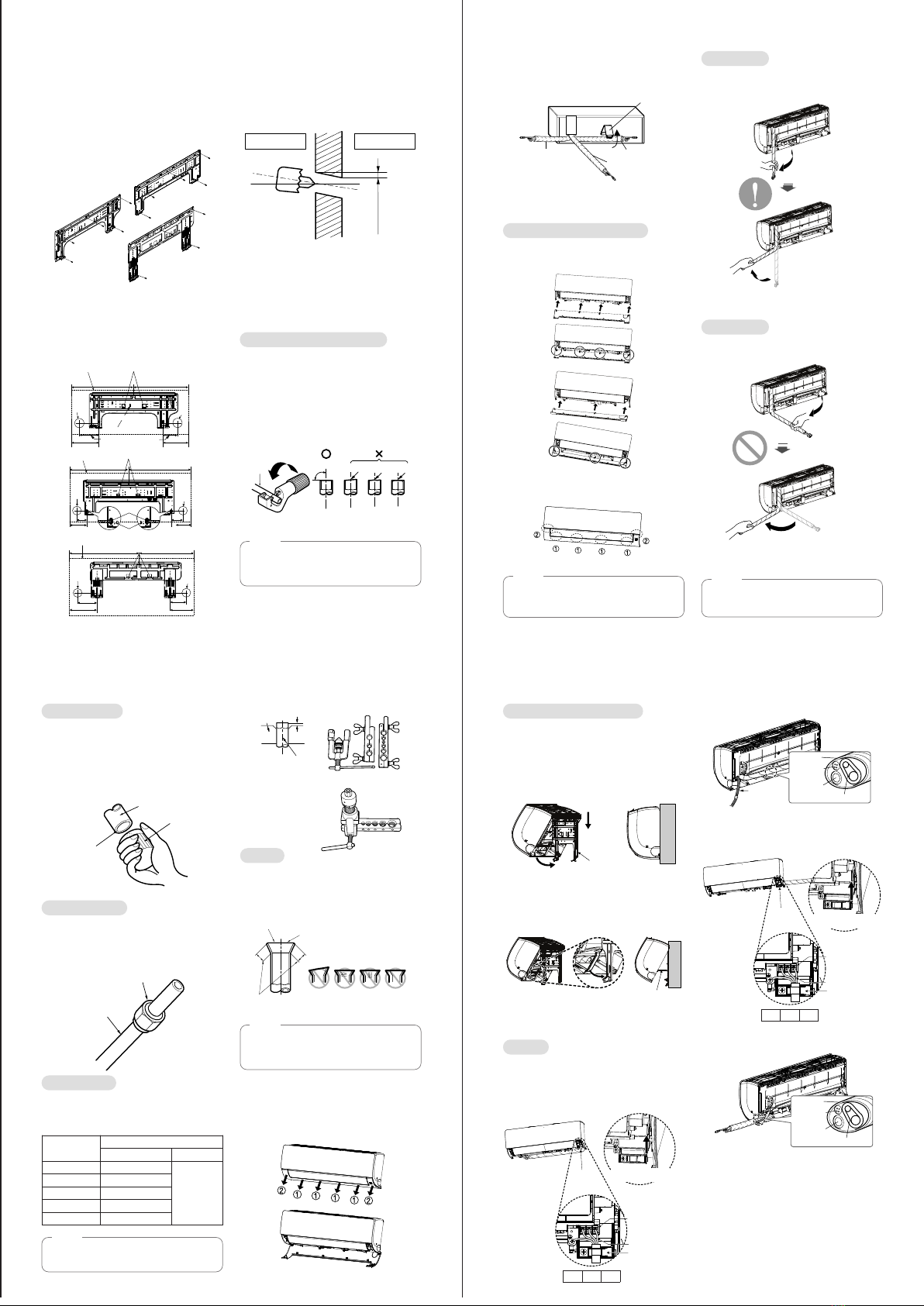
1Mount the tubing holder in the original
position.
2Ensure that the hooks are properly seated
on the installation plate by moving it left
and right.
3Press the lower left and right sides of the
unit against the installation plate until the
hooks engage into their slots (clicking
sound).
4Finish the assembly by screwing the unit
to the installation plate by using two pieces
of type "C" screws. And assemble a chas-
sis cover.
* The feature can be changed according to
type of model.
Finishing the indoor unit
installation
Checking the Drainage
1Pour a glass of water on the evaporator.
2Ensure the water flows through the drain
hose of the indoor unit without any leak-
age and goes out the drain exit.
* The feature can be changed according to
type of model.
1The drain hose should point downward for
easy drain flow.
Drain piping
Downward slope
Drain pan
Drain
hose
Leakage
checking
Connecting area
drain hose
Leakage
checking
To check the drainage.
CAUTION
!
The indoor unit can be dropped from the
wall, the indoor unit is not screwed
correct position on the install plate.
To avoid the gap between the indoor unit
and wall , screw the indoor unit to the
install plate correctly.
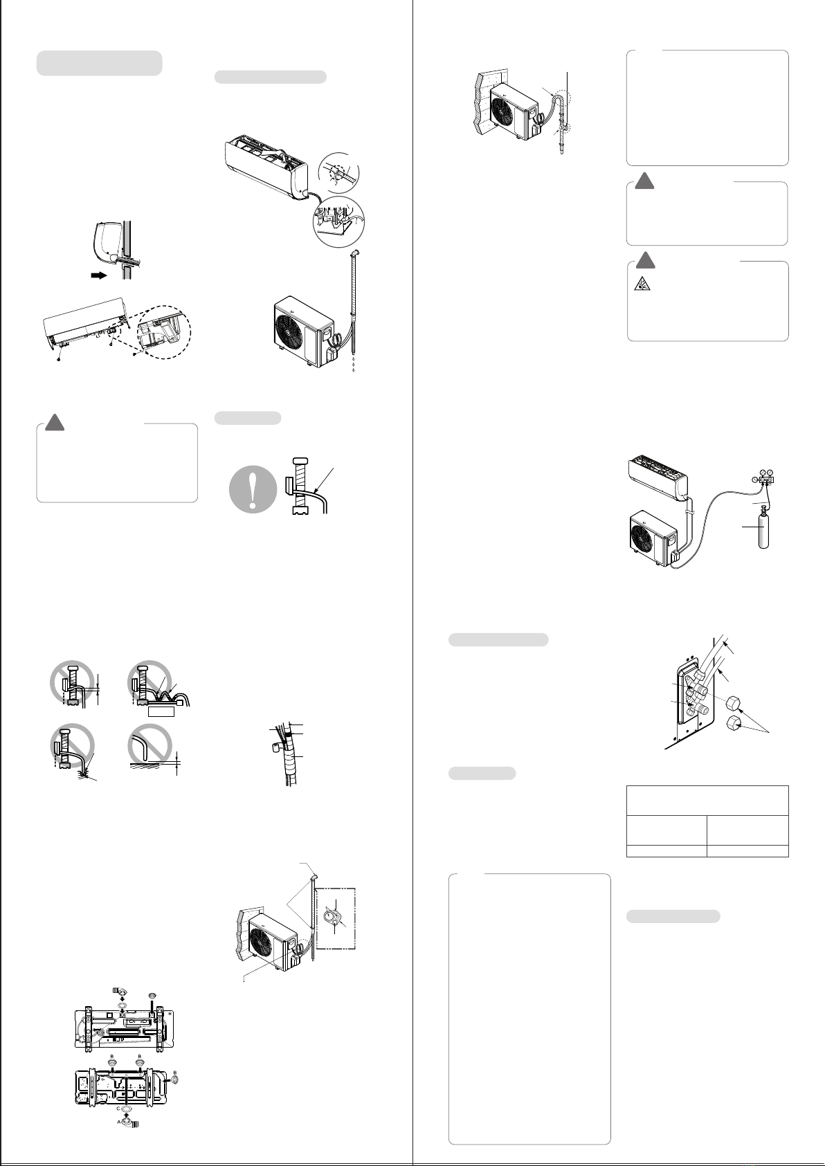
To avoid nitrogen entering the refrigerant
system in a liquid state, the top of the cylin-
der must be higher than its bottom when
you pressurize the system. Usually, the cylin-
der is used in a vertical standing position.
Air Purging
The air and moisture remaining in the
refrigerant system have undesirable effects as
indicated below.
1Pressure in the system rises.
2Operating current rises.
3 Cooling(or heating) efficiency drops.
4 Moisture in the refrigerant circuit may
freeze and block capillary tubing.
5 Water may lead to corrosion of parts in the
refrigeration system.
Therefore, after evacuating the system, take a
leak test for the piping and tubing between
the indoor and outdoor unit.
Air purging with vacuum pump
1Preparation
- Check that each tube(both liquid and gas
side tubes) between the indoor and out-
door units have been properly connected
and all wiring for the test run has been
completed. Remove the service valve
caps from both the gas and the liquid side
on the outdoor unit. Note that both the
liquid and the gas side service valves on
the outdoor unit are kept closed at this
stage.
2 Leak test
- Connect the manifold valve(with pressure
gauges) and dry nitrogen gas cylinder to
this service port with charge hoses.
Seal a small opening
around the pipings
with gum type sealant.
Trap
Trap
- Do a leak test of all joints of the tubing(both
indoor and outdoor) and both gas and liquid
side service valves. Bubbles indicate a leak.
Be sure to wipe off the soap with a clean
cloth.
- After the system is found to be free of leaks,
relieve the nitrogen pressure by loosening
the charge hose connector at the nitrogen
cylinder. When the system pressure is
reduced to normal, disconnect the hose from
the cylinder.
There is a risk of fire and explosion.
Inert gas (nitrogen) should be used
when you check plumbing leaks, cleaning
or repairs of pipes etc. If you are using
combustible gases including oxygen,
product may have the risk of fires and
explosions.
Be sure to use a manifold valve for air purg-
ing. If it is not available, use a stop valve for
this purpose. The knob of the 3-way valve
must always be kept close.
- Pressurize the system to maximum
17.6 kg/cm2G (R22 model) or 28.1 kg/cm2G
(R410A model) with dry nitrogen gas and
close the cylinder valve when the gauge
reading reaches 17.6 kg/cm2G (R22 model)
or 28.1 kg/cm2G (R410A model). Next step
is leak test with liquid soap.
Indoor unit
Outdoor unit
Manifold valve
Charge hose
Nitrogen gas
cylinder(in vertical
standing position)
Pressure
gauge
2Do not make drain piping like the
following.
* The feature can be changed according to
type of model.
Installing drain piping of the
outdoor unit
Depending on installation site, it may be
required to install drain plug for drainage
(Supplied with the unit). In cold areas, do not
use a drain hose with the outdoor unit.
Otherwise, drain water may freeze, impairing
the heating performance.
1See the figure below for installation of the
drain plug.
A Drain nipple
B Drain cap
C Drain washer
2
Connect a field supplied vinyl hose to the
drain nipple (A). If the hose is too long and
hangs down, fix it carefully to prevent kinks.
* The feature can be changed according to
type of model.
Do not raise
Water
leakage
Tip of drain hose
dipped in water
Water
leakage Ditch
Less than
50mm gap
Accumulated
drain water
Air
Waving
Water
leakage
B
A
C
• 6.6 kW
• 2.5/3.5/5.0 kW
Forming the Piping
Form the piping by wrapping the connecting
portion of the indoor unit with insulation material
and secure it with two kinds of vinyl tapes.
- If you want to connect an additional drain
hose, the end of the drain outlet should be
routed above the ground. Secure the drain
hose appropriately.
In cases where the outdoor unit is installed
below the indoor unit perform the following.
1 Tape the piping, drain hose and connecting
cable from down to up.
2Secure the tapped piping along the exteri-
or wall using saddle or equivalent.
* The feature can be changed according to
type of model.
In cases where the Outdoor unit is installed
above the Indoor unit perform the following.
1 Tape the piping and connecting cable from
down to up.
2Secure the taped piping along the exterior
wall. Form a trap to prevent water entering
the room.
3Fix the piping onto the wall using saddle or
equivalent.
Drain hose Vinyl tape(narrow)
Pipe
Wrap with
vinyl tape(wide)
Taping
Saddle
Drain hose
Pipings
Connecting cable
Seal a small opening
around the pipings
with gum type sealant.
Trap is required to prevent water
from entering into electrical parts.
- Remove the caps from the 2-way and 3-way
valves.
- Remove the service-port cap from the 3-way
valve.
- Apply a soap water or a liquid neutral deter-
gent on the indoor unit connection or out-
door unit connections by a soft brush to
check for leakage of the connecting points of
the piping.
- If bubbles come out, the pipes have leakage
-
Connect the charge hose end described in
the preceding steps to the vacuum pump to
evacuate the tubing and indoor unit. Confirm
the "Lo" knob of the pressure Gauge is open.
Then, run the vacuum pump. The operation
time for evacuation varies with tubing length
and capacity of the pump. The following table
shows the time required for evacuation.
Soap water method
Evacuation * The feature can be changed according
a type of model.
- When the desired vacuum is reached, close
the knob of the 3-way valve and stop the
vacuum pump.
- With a service valve wrench, turn the valve
of liquid side counter-clockwise to fully open
the valve
- Turn the valve of gas side counter-clockwise
to fully open the valve
- Loosen the charge hose connected to the
gas side service port slightly to release the
pressure, then remove the hose.
- Replace the flare nut and its bonnet on the
gas side service port and fasten the flare nut
securely with an adjustable wrench. This
process is very important to prevent leakage
from the system
- Replace the valve caps at both gas and liquid
side service valves and fasten them tight.
This completes air purging with a vacuum
pump.
- Replace the pipe cover to the outdoor unit by
one screw. Now the air conditioner is ready
for test run.
Finishing the Job
Gas side
Outdoor unit
Liquid side
Cap
3-way or
2-way valve
3-way valve
Required time for evacuation when 30 gal/h
vacuum pump is used
If tubing length is
less than 10 m
(33 ft)
If tubing length is
longer than 10 m
(33 ft)
10 min. or more 15 min. or more
for R32 Only
• Electronic leak detectors shall be used to
detect flammable refrigerants, but the sensi-
tivity may not be adequate, or may need re-
calibration. (Detection equipment shall be cal-
ibrated in a refrigerant-free area.)
• Leak detection equipment shall be set at a
percentage of the LFL (Lower flammable
limit) of the refrigerant and shall be calibrated
to the refrigerant employed and the appropri-
ate percentage of gas (25 % maximum) is
confirmed.
• Leak detection fluids are suitable for use with
most refrigerants but the use of detergents
containing chlorine shall be avoided as the
chlorine may react with the refrigerant and
corrode the copper pipe-work.
• If a leak is suspected, all naked flames shall
be removed/extinguished.
• If a leakage of refrigerant is found which
requires brazing, all of the refrigerant shall be
recovered from the system, or isolated (by
means of shut off valves) in a part of the sys-
tem remote from the leak.
• Oxygen free nitrogen (OFN) shall be purged
through the system both before and during
the brazing process.
NOTE
* How to enter the installer mode
* How to set the code


 null")