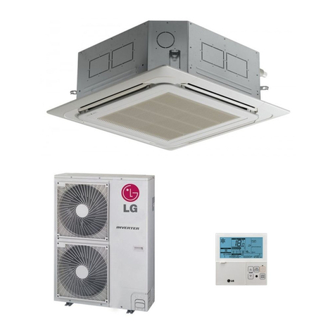
LG ARND203DCR4 User manual

INSTALLATION MANUAL
AIR
CONDITIONER
Please read this installation manual completely before installing the product.
Installation work must be performed in accordance with the national wiring standards
by authorized personnel only.
Please retain this installation manual for future reference after reading it thoroughly.
www.lghvac.com
www.lg.com
Copyright © 2021 LG Electronics Inc. All Rights Reserved.
ENGLISH
LG SPLIT COMPACT DEDICATED OUTDOOR AIR SYSTEM(DOAS)
MFL71810402
Rev.00

Due to our policy of continuous product innovation, some specifications may change without notification.
©LG Electronics U.S.A., Inc., Englewood Cliffs, NJ. All rights reserved. “LG” is a registered trademark of LG Corp.
2
PROPRIETARY DATA NOTICE
This document, as well as all reports, illustrations, data, information, and
other materials are the property of LG Electronics U.S.A., Inc., and are
disclosed by LG Electronics U.S.A., Inc., only in confidence.
Do not throw away, destroy, or lose this manual.
Please read carefully and store in a safe place for future reference.
Content familiarity required for proper installation.
The instructions included in this manual must be followed to prevent prod- uct
malfunction, property damage, injury, or death to the user or other people.
Incorrect operation due to ignoring any instructions will cause harm or damage.
A summary of safety precautions begins on page 4.
For more technical materials such as submittals, engineering
databooks, and catalogs, visit www.lghvac.com.
For continual product development, LG Electronics U.S.A., Inc. reserves the right to change specifications without notice.
©LG Electronics U.S.A., Inc.
This document, as well as all reports, illustrations, data, information, and other materials are the property of LG Electronics U.S.A., Inc.

Due to our policy of continuous product innovation, some specifications may change without notification.
©LG Electronics U.S.A., Inc., Englewood Cliffs, NJ. All rights reserved. “LG” is a registered trademark of LG Corp.
3
TABLE OF CONTENTS
SAFTYPRECAUTION ...................................................................................................................................................... 4
PRODUCT OVERVIEW.................................................................................................................................................... 8
CONTROLLEROVERVIEW............................................................................................................................................. 9
UNIT NOMENCLATURE................................................................................................................................................. 10
R410AREFRIGERANT..................................................................................................................................................11
GENERALDATA............................................................................................................................................................12
ELECTRICALDATA....................................................................................................................................................... 13
DIMENSION.................................................................................................................................................................... 15
REFRIGERANT FLOWDIAGRAM ................................................................................................................................. 16
WIRINGDIAGRAM ......................................................................................................................................................... 17
INSTALLATION............................................................................................................................................................... 18
ServiceClearance....................................................................................................................................................... 20
UNITPIPING................................................................................................................................................................... 22
RefrigerantPipingInstallation..................................................................................................................................... 26
RefrigerantSystemEngineering and.......................................................................................................................... 26
AllowablePipeLength................................................................................................................................................. 26
SampleLayouts .......................................................................................................................................................... 27
ELECTRICALINFORMATION........................................................................................................................................ 28
Field-MountedSensors........................................................................................................................................... 34
LEAK / PRESSURECHECKANDEVACUATION......................................................................................................... 36
Leak/PressureCheck................................................................................................................................................ 36
Evacuation................................................................................................................................................................... 37
CHARGINGREFRIGERANT.......................................................................................................................................... 39
CONTROLLER................................................................................................................................................................ 40
Overview................................................................................................................................................................. 40
ElectricalSpecifications.......................................................................................................................................... 40
Connectingto the WebUI ....................................................................................................................................... 40
ServicePassword.................................................................................................................................................... 41
StartupSettings....................................................................................................................................................... 41
IP Address............................................................................................................................................................... 41
DOASUnitAddressSetting.................................................................................................................................... 41
CentralControllerSetting........................................................................................................................................ 42
MainControlBoardTerminalConnections................................................................................................................. 45
CARELControlBoardTerminalConnections......................................................................................................... 45
LG ControlBoardLayout........................................................................................................................................ 46
Navigation................................................................................................................................................................... 49
MainStatusScreen..................................................................................................................................................... 50
MainMenuNavigation................................................................................................................................................ 51
SoftwareUpdate......................................................................................................................................................... 52
INSTALLATIONCHECKLIST.......................................................................................................................................... 53

Due to our policy of continuous product innovation, some specifications may change without notification.
©LG Electronics U.S.A., Inc., Englewood Cliffs, NJ. All rights reserved. “LG” is a registered trademark of LG Corp.
4
SAFTY PRECAUTION
The instructions below must be followed to prevent product malfunction, property damage, injury or death to the user or
other people. Incorrect operation due to ignoring any instructions will cause harm or damage. The level of seriousness
is classified by the symbols below
INSTALLATION
TABELE OF SYMBOLS
DANGER
This symbol indicates an imminently hazardous situation which, if not avoided, will result in death or serious injury.
WARNING
This symbol indicates a potentially hazardous situation which, if not avoided, could result in death or serious injury.
CAUTION
This symbol indicates a potentially hazardous situation which, if not avoided, may result in minor or moderate injury.
Note:
This symbol indicates situations that may result in equipment or property damage accidents only.
This symbol indicates an action that should not be performed.
DANGER
Do not store or use flammable gas or combustibles
near the unit.
There is risk of fire, explosion, physical injury or death
Do not supply power to the unit until all wiring and
piping are completed or reconnected and checked.
There is risk of physical injury or death due to electric shock.
WARNING
Do not install or remove the unit by yourself (end-user).
Ask the dealer or an LG trained technician to install the
unit
Improper installation by the user may result in water leakage,
fire, explosion, electric shock, physical injury or death.
Installation, startup, and service must be performed by a
qualified installer or a service agency.
Improper installation, adjustment, service, maintenance, or
alteration can cause personal injury or loss of life.
For replacement of an installed unit, always contact a
trained service provider.
There is risk of fire, electric shock, explosion, and physical
injury or death
Periodically check that the outdoor unit is not damaged.
There is risk of explosion, physical injury, or death.
Replace all control box and panel covers.
If cover panels are not installed securely, dust, water and
animals may enter the unit, causing fire, electric shock, and
physical injury or death.
Always check for system refrigerant leaks after the unit
has been installed or serviced.
Exposure to high concentration levels of refrigerant gas may
lead to illness or death
Do not install the unit using defective hanging,
attaching, or mounting hardware.
There is risk of physical injury or death.
Wear protective gloves when handling equipment.
Sharp edges may cause personal injury.
Dispose of the packing materials safely.
•Packing materials, such as nails and other metal or
wooden parts may cause puncture wounds or other
injuries.
•Tear apart and throw away plastic packaging bags so that
children may not play with them and risk suffocation and
death.
Do not install the unit in any location exposed to open
flame or extreme heat.
hands.
There is risk of fire, electric shock, explosion, and physical
injury or death.
Install the unit considering the potential for earthquakes.
Improper installation may cause the unit to fall, resulting in
physical injury or death.
Do not change the settings of the protection devices.
If the pressure switch, thermal switch, or other protection
device is shorted and forced to operate improperly, or parts
other than those specified by LG are used, there is risk of fire,
electric shock, explosion, and physical injury or death.
If the unit is installed in a small space, take measures to
prevent the refrigerant concentration from exceeding
safety limits in the event of a refrigerant leak.
Consult the latest edition of ASHRAE (American Society of
Heating, Refrigerating, and Air Conditioning Engineers)
Standard 15. If the refrigerant leaks and safety limits are
exceeded, it could result in personal injuries or death from
oxygen depletion
Do nottouchtheunitwithwet

Due to our policy of continuous product innovation, some specifications may change without notification.
©LG Electronics U.S.A., Inc., Englewood Cliffs, NJ. All rights reserved. “LG” is a registered trademark of LG Corp.
CAUTIONS
Be very careful when transporting the product.
•Do not attempt to carry the product without assistance.
•Some products use polypropylene bands for packaging. Do not use polypropylene bands to lift the unit.
•Suspend the unit from the base at specified positions.
•Support the unit at a minimum of four points to avoid slippage from rigging apparatus.
•Failure to follow these directions may result in minor or moderate physical injury.
Note:
Properly insulate all cold surfaces to prevent “sweating.”
Cold surfaces such as uninsulated pipe can generate
condensate that may drip and cause a slippery floor condition
and/or water damage to walls.
Installation, startup, and service must be performed by a
qualified installer, service agency, or gas supplier.
Improper installation, adjustment, service, maintenance, or
alteration can cause property damage
When installing the unit in a hospital, mechanical room, or
similar electromagnetic field (EMF) sensitive environment,
provide sufficient protection against electrical noise.
Inverter equipment, power generators, high-frequency medical
equipment, or radio communication equipment may cause the
air conditioner to operate improperly. The unit may also affect
such equipment by creating electrical noise that disturbs
medical treatment or image broadcasting.
Do not use the product for special purposes such as
preserving foods, works of art, wine coolers, or other
precision air conditioning applications.
There is risk of property damage.
Do not make refrigerant substitutions. Use R410A only.
If a different refrigerant is used, or air mixes with original
refrigerant, the unit will malfunction and become damaged.
Do not install the unit in a noise sensitive area.
When connecting refrigerant tubing, remember to allow
for pipe expansion.
Improper piping may cause refrigerant leaks and system malfunction
Take appropriate actions at the end of HVAC equipment
life to recover, recycle, reclaim or destroy R410A
refrigerant according to applicable U.S. Environmental
Protection Agency (EPA) rules.
Periodically check that the outdoor unit is not damaged.
There is a risk of equipment damage.
Install the unit in a safe location where no one can step on
or fall onto it.
hanging, attaching, or mounting hardware.
There is risk of unit and property damage.
Install the drain trap to ensure adequate drainage.
There is a risk of water leakage and property damage.
Don’t store or use flammable gas/combustibles near
the unit.
There is risk of product failure.
Always check for system refrigerant leaks after the unit
has been installed or serviced.
Low refrigerant levels may cause product failure.
Ductwork and other installed airflow restriction devices
such as filters shall not exceed the rated maximum static
pressure limits of the DOAS fan assembly.
Doing so may cause product malfunction
5
Do notinstall theunitwithdefective
OA Inlet (duct)shouldnotbe placed in an environment
where maybe exposedto harmfulvolatile organic
compounds(VOCs), or in environments wherethereis
improperairmakeup or supplyor inadequateventilation.

Due to our policy of continuous product innovation, some specifications may change without notification.
©LG Electronics U.S.A., Inc., Englewood Cliffs, NJ. All rights reserved. “LG” is a registered trademark of LG Corp.
WIRING
DANGER
High voltage electricity is required to operate this system.
Adhere to the National Electrical Codes and these
instructions when wiring.
Improper connections and inadequate grounding can cause
accidental injury or death.
Always ground the unit following local, state, and National
Electrical Codes.
Turn the power off at the nearest disconnect before
servicing the equipment.
Electric shock can cause physical injury or death.
Properly size all circuit breakers or fuses.
There is risk of fire, electric shock, explosion, physical injury or
death
WARNING
The information contained in this manual is intended for
use by an experienced, trained electrician familiar with the
U.S. National Electric Code (NEC) who is equipped with
the proper tools and test instruments.
Failure to carefully read and follow all instructions in this
manual can result in injury or death.
Ensure the unit is connected to a dedicated power source
that provides adequate power.
If the power source capacity is inadequate or the electric work
is not performed properly, it may result in fire, electric shock,
physical injury or death.
Refer to local, state, and federal codes, and use power
wires of sufficient current capacity and rating.
Wires that are too small may generate heat and cause a fire
and physical injury or death.
Secure all field wiring connections with appropriate wire
strain relief.
Improperly securing wires will create undue stress on
equipment power lugs. Inadequate connections may generate
heat, cause a fire and physical injury or death.
Properly tighten all power connections.
Loose wiring may overheat at connection points, causing a
fire, physical injury or death
Note:
Do not supply power to the unit until all electrical
wiring, controls wiring, piping, installation, and refrigerant
system evacuation are completed.
The system will malfunction.
The information contained in this manual is intended for
use by an experienced, trained electrician familiar with the
U.S. National Electric Code (NEC) who is equipped with
the proper tools and test instruments.
Failure to carefully read and follow all instructions in this manual
can result in equipment malfunction or property damage.
6

Due to our policy of continuous product innovation, some specifications may change without notification.
©LG Electronics U.S.A., Inc., Englewood Cliffs, NJ. All rights reserved. “LG” is a registered trademark of LG Corp.
OPERATION
DANGER
Do not provide power to or operate the unit if it is
flooded or submerged.
There is risk of fire, electric shock, physical injury or death.
Use a dedicated power source for this product.
There is risk of fire, electric shock, physical injury or death.
Do not operate the disconnect switch with wet hands.
There is risk of fire, electric shock, physical injury or death.
Periodically verify the hanging bolts and other hardware
securing the unit have not deteriorated. If the unit falls from
its installed location, it can cause property damage, product failure,
physical injury or death.
If refrigerant gas leaks out, ventilate the area before
operating the unit.
If the unit is mounted in an enclosed, low-lying, or poorly
ventilated area and the system develops a refrigerant leak, it
may cause fire, electric shock, explosion, physical injury or
death
WARNING
Do not allow water, dirt, or animals to enter the unit.
There is risk of fire, electric shock, physical injury or death.
Do not touch refrigerant piping during or after
operation.
It can cause burns or frostbite.
Do not operate the unit with the panel(s) or protective
cover(s) removed; keep fingers and clothing away from
moving parts.
The rotating, hot, cold, and high-voltage parts of the unit can
cause physical injury or death.
Periodically check power cable and connection for
damage.
Cable must be replaced by the manufacturer, its service agent,
or similar qualified persons in order to avoid physical injury and
/ or electric shock.
Securely attach the electrical cover to the unit.
Non-secured electrical covers can result in burns or electric
shock due to dust or water in the service panel.
Ensure no power is connected to the unit other than as
directed in this manual. Remove power from the unit
before removing or servicing the unit.
There is risk of unit failure, fire, electric shock, physical injury
or death
Note:
Clean up the site after installation is finished, and check
that no metal scraps, screws, or bits of wiring have been
left inside or surrounding the unit.
Do not use this equipment in mission critical or special
purpose applications such as preserving foods, works of
art, wine coolers or refrigeration.
Do not allow water, dirt, or animals to enter the unit.
There is risk of unit failure
Do not block the inlet or outlet.
Unit may malfunction.
Do not operate the unit with the panel(s) opened or
removed; keep fingers and clothing away from moving
parts
Non-secured covers can result in malfunction due to dust or
water
Periodically verify the equipment mounting hardware has
not deteriorated.
If the base collapses, the unit could fall and cause property
damage or product failure.
Do not turn off the main power switch after operation
has been stopped.
Wait at least five (5) minutes before turning off the main power
switch, otherwise it will result in product malfunction.
7

Due to our policy of continuous product innovation, some specifications may change without notification.
©LG Electronics U.S.A., Inc., Englewood Cliffs, NJ. All rights reserved. “LG” is a registered trademark of LG Corp.
PRODUCT OVERVIEW
Split Compact DOAS Interior Components
8
Main Coil
Hot Gas Reheat Coil
EC motor
3D Plug Fan
Heat Recovery Unit
Control Box
-Web UI,
-BACnet IP, Modbus RTU
Bottom Access Panel
(Fan Motor Assembly)
Filters
(MERV8)
Drain
(Gravity)
Drain
(Pump)

Due to our policy of continuous product innovation, some specifications may change without notification.
©LG Electronics U.S.A., Inc., Englewood Cliffs, NJ. All rights reserved. “LG” is a registered trademark of LG Corp.
CONTROLLER OVERVIEW
9
No
Description
1
CAREL® Controller
2
Main Module
3
4
5
6
7
HR Unit PCB
8
SMPS
9
Transformer
10
RS485 1
11
RS485 2
12
2 3 4 56
Top Panel Bottom Panel
17
10
11
8
12
9
UI Module
NTCModule
Main Coil EEV Module
ReheatCoil EEVModule
Relay

Due to our policy of continuous product innovation, some specifications may change without notification.
©LG Electronics U.S.A., Inc., Englewood Cliffs, NJ. All rights reserved. “LG” is a registered trademark of LG Corp.
UNIT NOMENCLATURE
FAMILY
ARN =Multi-V Indoor Unit
R410A Refrigerant
TYPE
D = Dedicated Outdoor Air System (DOAS)
AIR FLOW RATE (CFM)
15 = 1,500 CFM
20 = 2,000CFM
ELECTRICAL RATINGS
U = 208/230V or 460V, 60Hz, 3Phase
3 = 208/230V, 60Hz, 1Phase
CHASSIS
DB = Type B (Rooftop DOAS)
DC = Type C (Compact DOAS)
ENERGY RECOVERY WHEEL
E= With Energy Recovery Wheel
R= Without Energy Recovery Wheel
GENERTATION
4= Fourth
ARN
D
20
3
DC
R
4
10

Due to our policy of continuous product innovation, some specifications may change without notification.
©LG Electronics U.S.A., Inc., Englewood Cliffs, NJ. All rights reserved. “LG” is a registered trademark of LG Corp.
R410A REFRIGERANT
R410A refrigerant has a higher operating pressure in comparison to R22 refrigerant and, therefore, all piping system
materials installed must have a higher resisting pressure than the materials traditionally used in R22 systems.
R410A refrigerant is an azeotrope of R32 and R125, mixed at 50:50, so the ozone depletion potential (ODP) is 0.
WARNING
•Do not place the refrigerant cylinder in direct sunlight. Refrigerant cylinder may explode causing severe injury
or death.
Note:
•Because R410A is a combination of R32 and R125, the required additional refrigerant must be charged in its
liquid state. If the refrigerant is charged in its gaseous state, its composition changes and the system will not
work properly.
•Do not heat piping more than necessary during installation. Piping may become soft and fail when
pressurized.
•Do not use any piping that has not been approved for use in high-pressure refrigerant systems. Piping wall
thickness must comply with the applicable local, state, and federal codes for the 551 psi design pressure of
R410A. Inadequate piping may fail when pressurized.
11

Due to our policy of continuous product innovation, some specifications may change without notification.
©LG Electronics U.S.A., Inc., Englewood Cliffs, NJ. All rights reserved. “LG” is a registered trademark of LG Corp.
GENERAL DATA
12
Split Compact DOAS
US Model Number
ARND203DCR4
ARND153DCR4
Design Airflow(CFM)
2,000
1,500
ESP (in.Wg)
1.5
2.0
Airflow Range(CFM)
1,000 - 2,000
1,000 - 1,500
Cooling Mode Performance
OA EAT DB/WB (°F)
Unit LAT DB/WB (°F)
52.9 / 52.5
52.9 / 52.5
Total Cooling Capacity (Btu/h)
143,100
120,000
Hot Gas Reheat capacity (Btu/h)
30,000
24,000
Heating Mode Performance
OA EAT DB/WB (°F)
Unit LAT DB(°F)
70 / 53.5
70 / 53.5
Capacity (Btu/h)
59,900
51,000
Unit Data
Refrigerant Type
R410A
R410A
Refrigerant Trim Charge Correction Factor
5.45
5.45
Refrigerant Control
EEV
EEV
Coil Material, Tube/Fin
CU / AL
CU / AL
Fin Type
LG Louver / PCM
LG Louver / PCM
Corrosion Protection
galvanizing, Non-Chromate
Sound Power dB(A)
72
74
Net Unit Weight (lbs.)
390
390
Shipping Weight (lbs.)
430
430
Communication Cable1 (No. x AWG)
4 x 18
4 x 18
Fan
Supply Fan Quantity
1
1
Supply Fan Type
3D Plug
3D Plug
Supply Fan Diameter(in.)
15.7
15.7
Supply Fan Motor Output(HP/W)
1 / 750
1 / 750
Supply Fan Motor/Drive
ECM / Direct
ECM / Direct
Piping2
Liquid Connection Size (in, OD)
1/2 Brazed
1/2 Brazed
High Pressure Vapor Connection Size (in, OD)
7/8 Brazed
3/4 Brazed
Low Pressure Vapor Connection Size (in, OD)
1- 1/8 Brazed
1- 1/8 Brazed
Condensate Drain OD (in)
1
1
Filter
Outdoor
2" Merv8 (25” x 20”) x 2
1. Communication between ODU to DOAS to be 18AWG, 4 conductor
2. LG requires that LATS software be used on all projects to ensure correct line sizing. Designer must verify the shop drawing design against the as
built design using LATS. Contractor must also use LG manufactured Y-Branch Kits only
95 / 78
95 / 78
47 /43
47 /43
MainCoil(ø xRowxColumnxFPIxL) xQty.
ReheatCoil(ø xRowxColumnxFPIxL) xQty.(7.0x 1 x 24 x19 x1390) x 1 ( 7.0x 1 x 24 x19 x1390) x 1
(7.0x 3 x 24 x19 x1390) x 1 ( 7.0x 3 x 24 x19 x1390) x 1

Due to our policy of continuous product innovation, some specifications may change without notification.
©LG Electronics U.S.A., Inc., Englewood Cliffs, NJ. All rights reserved. “LG” is a registered trademark of LG Corp.
ELECTRICAL DATA
Model Name
Power Supply
FLA
MCA
MOP
Hz
Volts
Voltage Range
Phase
ARND203DCR4
60
208/230
187-253
1
15
ARND153DCR4
6.0
7.5
15
MCA: Minimum Circuit Ampacity
MOP: Maximum Overcurrent Protection: (Largest motor FLA x 2.25) + (Sum of other motor FLA) rounded down to the nearest standard fuse size
13
6.0
7.5

Due to our policy of continuous product innovation, some specifications may change without notification.
©LG Electronics U.S.A., Inc., Englewood Cliffs, NJ. All rights reserved. “LG” is a registered trademark of LG Corp.
DIMENSION
14

Due to our policy of continuous product innovation, some specifications may change without notification.
©LG Electronics U.S.A., Inc., Englewood Cliffs, NJ. All rights reserved. “LG” is a registered trademark of LG Corp.
REFRIGERANT FLOW DIAGRAM
COOLING
DEHUMIDIFICATION
15

Due to our policy of continuous product innovation, some specifications may change without notification.
©LG Electronics U.S.A., Inc., Englewood Cliffs, NJ. All rights reserved. “LG” is a registered trademark of LG Corp.
REFRIGERANT FLOW DIAGRAM
HEATING
16
Note:
Cutting line of insulation must look upper direction. Thickness
of insulation is 15mm(Gas pipe) and 19mm(Liquid pipe) or over

Due to our policy of continuous product innovation, some specifications may change without notification.
©LG Electronics U.S.A., Inc., Englewood Cliffs, NJ. All rights reserved. “LG” is a registered trademark of LG Corp.
WIRING DIAGRAM
17
RD
YL
RD YL
RD YL
(GN) (BK)(YL)
BK(YL) (WH)
BL
WH
1

Due to our policy of continuous product innovation, some specifications may change without notification.
©LG Electronics U.S.A., Inc., Englewood Cliffs, NJ. All rights reserved. “LG” is a registered trademark of LG Corp.
INSTALLATION
Receiving and Inspection
Upon receiving the product, verify that all pieces listed on
the bill of lading, delivery receipt, or packing list have
been received.
Inspect each crate or carton for shipping damage before
accepting delivery. Alert the carrier if any damage is
detected; do not refuse shipment. The customer must
note any damage (or shortage of items) on the delivery
receipt and all copies of the bill of lading, which then
should be signed by the delivery carrier. Photograph the
damage if possible. If damaged, immediately contact your
manufacturer’s representative.
Handling
Handle in such a manner as to keep from scratching or
chipping the unit.
Storage
Units are protected against damage during shipment. If
the unit cannot be installed and operated immediately,
precautions need to be taken to prevent deterioration of
the unit during storage. The user assumes responsibility
of the unit and accessories while in storage. The
manufacturer will not be responsible for damage during
storage. These suggestions are provided solely as a
convenience to the user.
The ideal environment for the storage of units and
accessories is indoors, above grade, in a low humidity
atmosphere which is sealed to prevent the entry of
blowing dust, rain, or snow. All accessories must be
stored indoors in a clean, dry atmosphere
Removing from Storage
As units are removed from storage to be installed in their
final location, they should be protected and maintained
in a similar fashion until the equipment goes into
operation.
Prior to installing the unit and system components,
inspect the unit assembly to make sure it is in working
order.
1. Check all fasteners, set screws on the fan, wheel,
bearings, drive, motor base, and accessories for
tightness
2. Rotate the fan wheel(s) by hand and assure no
parts are rubbing.
Assemblies
Blower - One plenum-type fans (LG 3D Plug). All units
are equipped with a plenum fan for SupplyAir
Coils - Evaporator coil and Reheat coil
Filters –Two (2) inch thick pleated paper MERV
8(standard) or tow (2) inch thick pleated paper MERV 13
filters in the supply air stream.
Split DX system - Unit ordered with a Multi V 5 outdoor
unit
Airflow Arrangement
The unit is capable of Constant Air volume (CAV) with
two different mode. One is “Air Volume (CFM) Control”
which follow automatically the target CFM value, other is
“Constant Volume” control which is manually set up
using the Air volume with RPM (%) setting.
Location Selection
DANGER
To avoid the possibility of fire, do not install the unit in an
area where combustible gas may generate, flow,
stagnate, or leak. Failure to do so will cause serious
bodily injury or death. Before beginning installation, read
the safety summary at the beginning of this manual.
Note:
Select a location for installing the unit that meets the following
conditions:
1. Where there is enough structural strength to bear the weight
of the unit.
2.Operating sound from the unit will not disturb occupants.
3.Include enough space for service access.
4.Include space for drainage to ensure condensate flows
properly out of the unit when it is in cooling mode.
5.Use a level indicator to ensure the unit is installed on a level
plane.
WARNING
Securely install threaded rod hangars (bolts) and hardware
to prevent the chassis falling from its installation location.
There is risk of personnel injury from falling equipment.
Installation work must be performed by trained personnel
and in accordance with all local or other applicable codes.
There is risk of injury to personnel from incorrect installation.
Note:
6.Ensure the unit is properly installed. Incorrectly installed
units can malfunction resulting in degraded performance or
an inoperative unit/ system.
18

Due to our policy of continuous product innovation, some specifications may change without notification.
©LG Electronics U.S.A., Inc., Englewood Cliffs, NJ. All rights reserved. “LG” is a registered trademark of LG Corp.
19
Roughing In the Indoor Unit
1. Determine the installation location. Ensure the
location has enough space to allow necessary duct
connections and maintenance access.
2. Select and Mark the position for fixing bolts
3. Drill the hole for set anchor on the face of ceiling.
Figure 9: Drill the hole
4. Securely install the four field-provided threaded rod
hangars to the overhead support locations.
-. Insert the set anchor and washer onto the
suspension bolts for locking the suspension blots
on the ceiling
-. Mount the suspension bolts to the set anchor
firmly.
-. Secure the installation plates onto the suspension
bolts (adjust level roughly) using nuts, washers
and springs washers.
Figure 10: Ceiling Anchor Installation
5. Hang the chassis from the four field-supplied
threaded rod hangars. Refer to the threaded rod
hangar details in Figure 11.
6. Use a level to ensure the chassis is level and
securely tighten the mounting nuts.
7. If local code requires an auxiliary drain pan under
the unit, install a field-provided auxiliary drain pan.
8. Connect ductwork to the unit as necessary.
Figure.11: Threaded Rod Hanger and Attaching Hardware
Figure.12: Split Compact DOAS Unit Dimensions.
Table.14: Dimensions and Weights.
Chassis
Code
Weight
(lbs.)
Major Dimensions (in.)
Mounting
Dimensions(in.)
W
H
D
M1
M2
M3
M4
M5
DC
390
75
21.7
45.1
77.2
37.3
1.1
6.8
0.9
M2
W
M1
D
H
M3
M4
M5
7.Securely install threaded rod hangars (bolts) and hardware
to prevent the chassis falling from its installation location.
There is risk of equipment or property damage from falling
equipment.
8.Use a level indicator to ensure the chassis is installed on a
level plane
CAUTION : Tighten the nut and bolt
to prevent unit falling.

Due to our policy of continuous product innovation, some specifications may change without notification.
©LG Electronics U.S.A., Inc., Englewood Cliffs, NJ. All rights reserved. “LG” is a registered trademark of LG Corp.
20
Ductwork Configuration
When connecting ducts, insert a canvas duct between
the main body and the duct.
• Use non-combustible duct components.
• Install sufficient insulation to prevent condensation
forming on outlet duct flanges and outlet ducts.
The contractor is responsible for providing transitions to
accommodate difference in sizing between the unit and
the building ducts. Duct connections to collar-type
openings can be made with S-cleats or overlapping joints.
Apply caulk around each duct connection. Failure to seal
duct connections can cause air leakage and system
performance problems.
Note:
•When an air duct which carries supply air or warm air
passes through a combustible roof, a clearance of one inch
must be maintained between the outside perimeter of
ductwork and any combustible materials, per NFPA
Standard 90A
Figure.13: Duct Connection Dimensions
Service Clearance
Allow service clearances as approximately indicated in
Figure 14. Refer to NEC and local for minimum
clearances around the unit and control panel.
Figure.14: Service Clearance Dimensions
Table.14: Duct Connection Dimension
Chassis
Code
SA Outlet
OA Inlet
L1
L2
L4
L5
DC
17.6
53.8
49
16.4
Table.14: Service Clearance Dimensions
[Unit : inch]
D2
D1
ISOMETRIC VIEW
Chassis
Code
Fan &
Motor
Assembly
Controller,
Cycle(HR),
Filter
Min
Distance
Min
Distance
A1
A2
B1
B2
C
D1
D2
DC
45.6
45.6
36
96.2
50.2
22
20
Service Access
(Sensor,Filter)
This manual suits for next models
1
Table of contents
Other LG Air Conditioner manuals
Popular Air Conditioner manuals by other brands

mundoclima
mundoclima CL23420 installation manual

Toshiba
Toshiba RAS-13SKHP-E Service manual

Mitsubishi Electric
Mitsubishi Electric MSZ-GE25VA operating instructions

Olimpia splendid
Olimpia splendid maeStro Pro Instructions for installation, use and maintenance

McQuay
McQuay MCK020A Technical manual

Panasonic
Panasonic PZ2 Series operating instructions

Mitsubishi Electric
Mitsubishi Electric Mr. Slim PUZ-M200YKA2.UK Service manual

Haier
Haier 2HUM14HC03-R2 installation manual

Whynter
Whynter ARC-12SDH instruction manual

Hitachi
Hitachi RAM-55QH4 Service manual

Cruisair
Cruisair Zephyr Installation and operation manual

Hitachi
Hitachi RA-13JF1 Operation and installation manual