2
Safety PrecautionsElectrical Data
About the Controls on
the Air Conditioner
Features and Installation
Before you call for service...
FOR YOUR RECORDS
Staple your receipt to this page in case you need it later.
Write down the model and serial numbers here:
Model #
Serial #
You can find them on a label on the side of each unit.
Dealer's Name
Date Purchased
Inside you will find many helpful hints on how to use and
maintain your air conditioner properly. Just a little preventive
care on your part can save you a great deal of time and
money over the life of your air conditioner.
You'll find many answers to common problems in the chart
of troubleshooting tips. If you review our chart of
Troubleshooting Tips first, you may not need to call for
service at all.
READ THIS MANUAL
CAUTION
• Contact an authorized Service technician for repair or
maintenance of this unit.
• The air conditioner is not intended for use by young
children or invalids without supervision.
• Young children should be supervised to ensure that they
do not play with the air conditioner.
Safety Precautions
Safety Precautions.............3
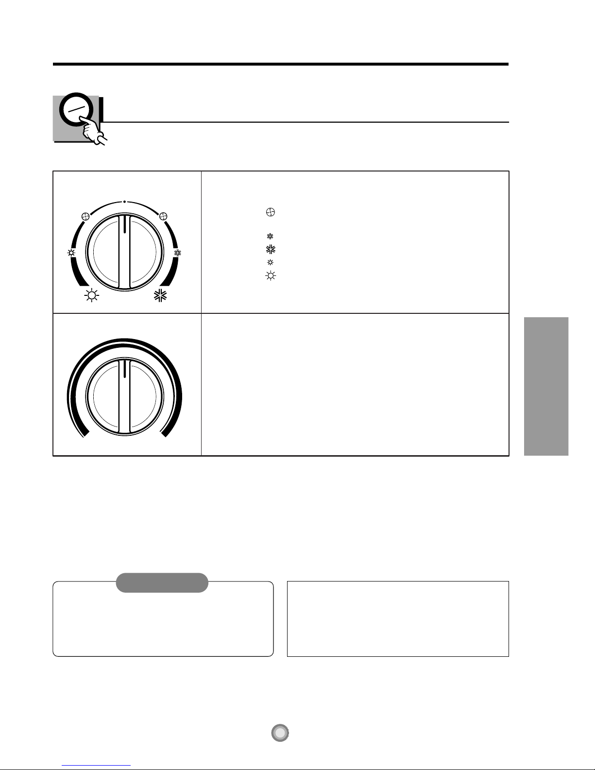
About the Controls on
the Air Conditioner
Controls..............................6
Ventilation ..........................8
Air Direction........................8
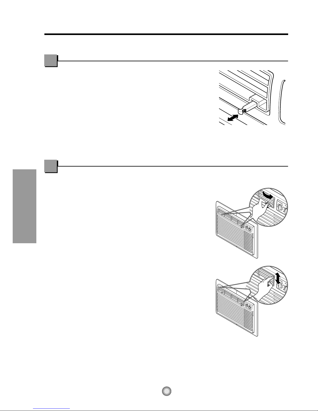
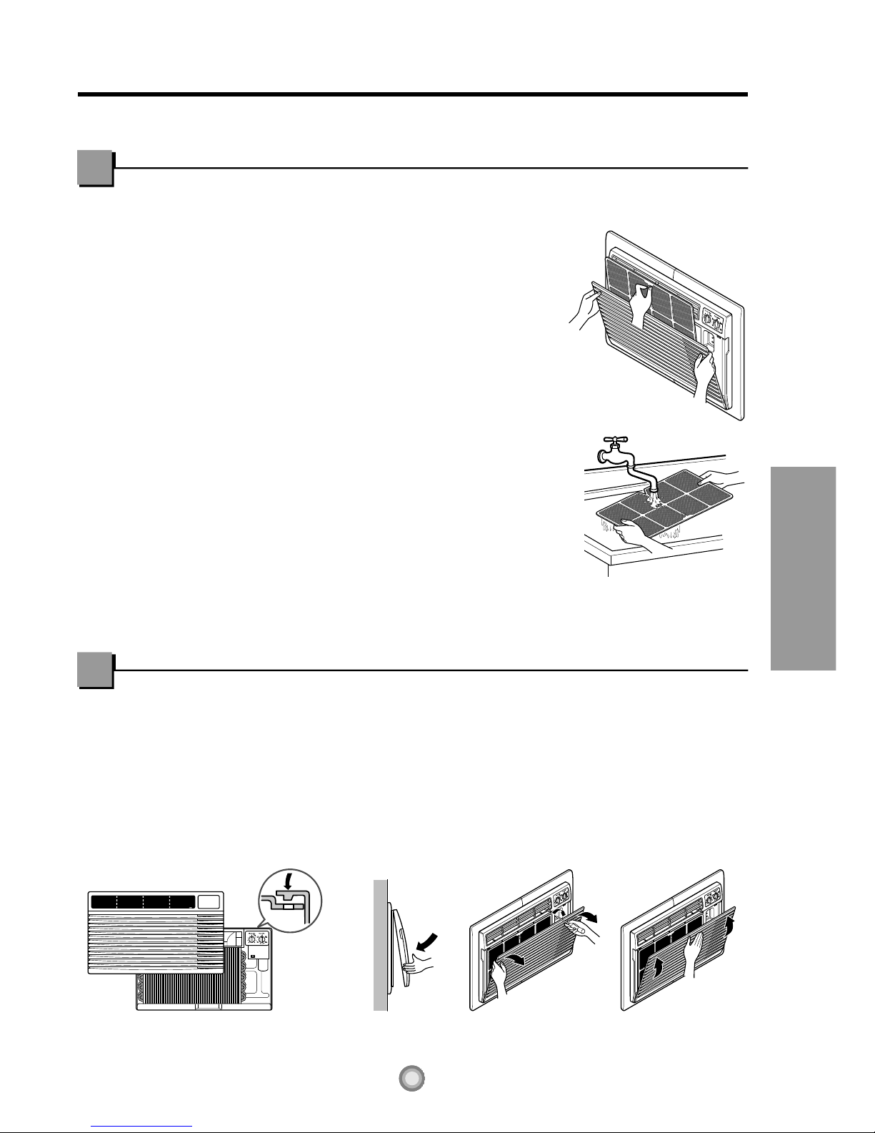
Care and Maintenance
Air Filter Cleaning...............9
How to Attach Front Grille to
Cabinet...............................9
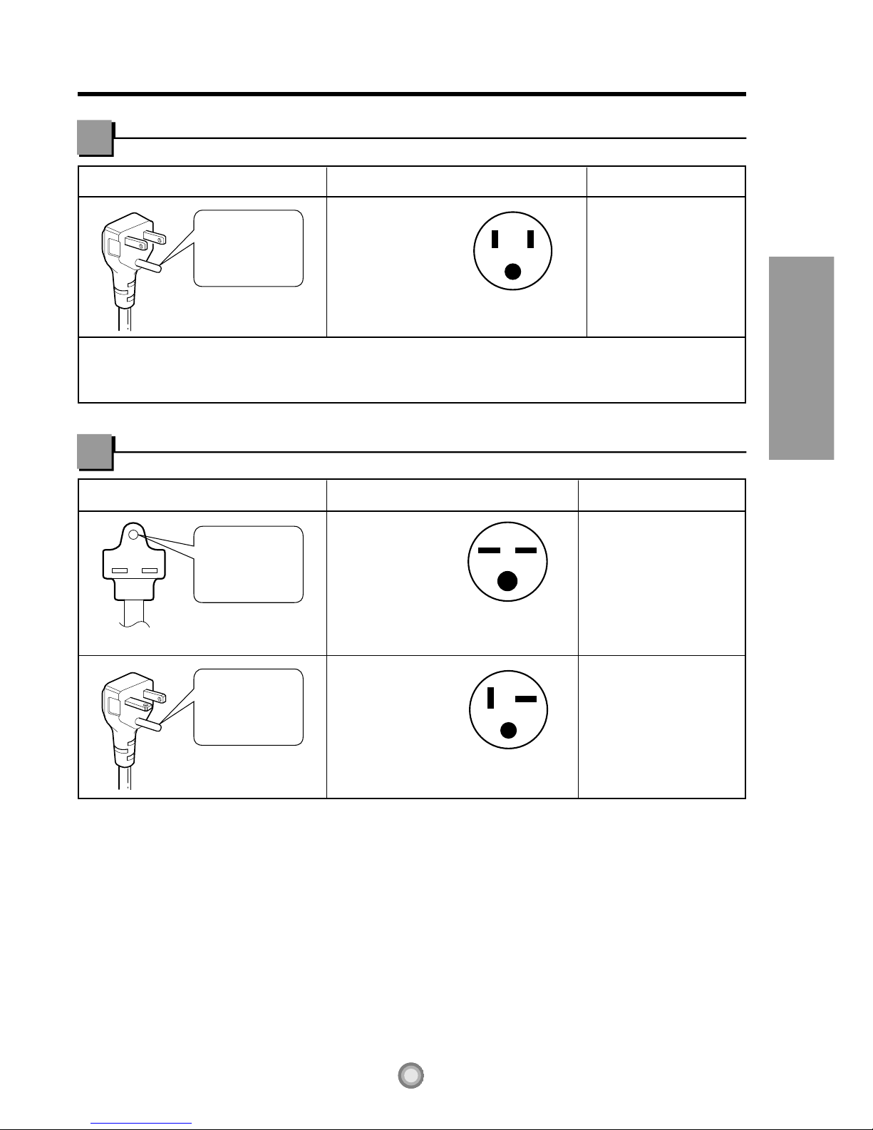
Electrical Data
Electrical Data....................5
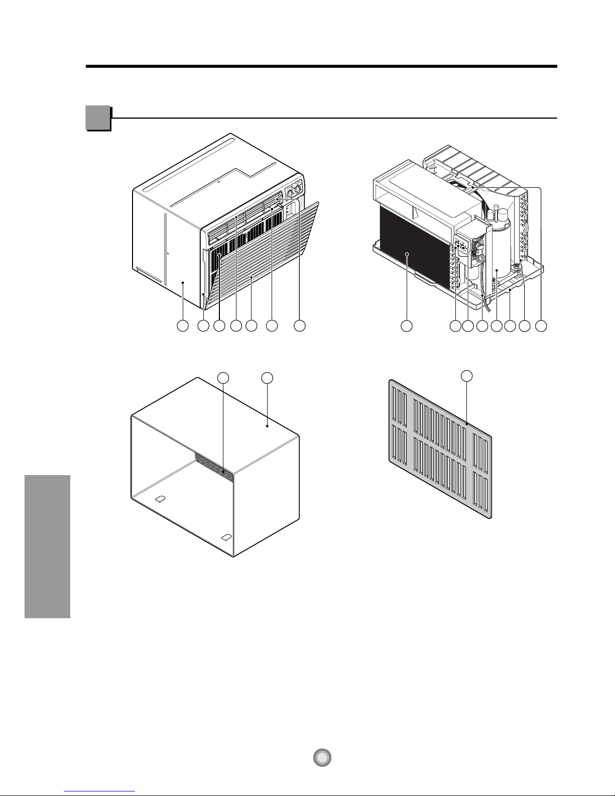
Features
and Installation
Features...........................10
How to Install the Unit......11
How to Replace the Unit ..11
Installation Kits Contents..12
Before you call
for service...
Normal Operation..............15
Abnormal Operation ..........15


 User manual")


 null")