- 4 -
Copyright ©2010 LG Electronics. Inc. All right reserved.
Only for training and service purposes LGE Internal Use Only
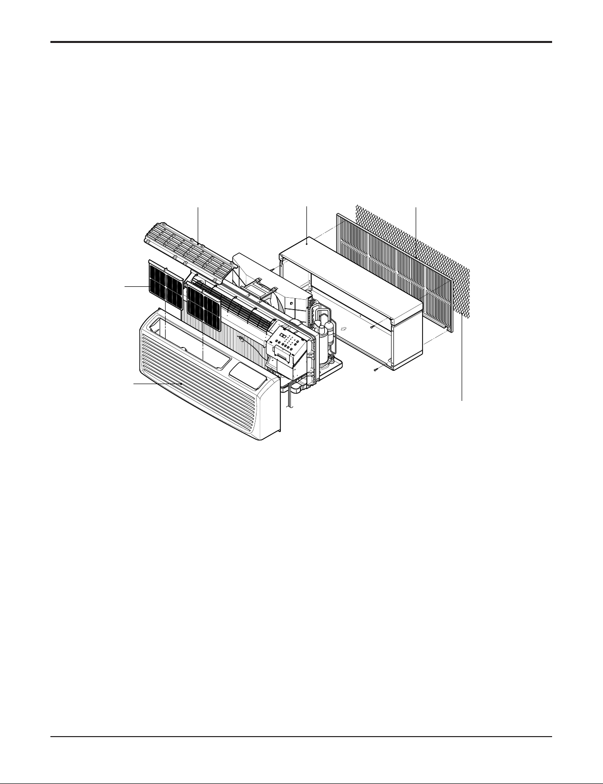
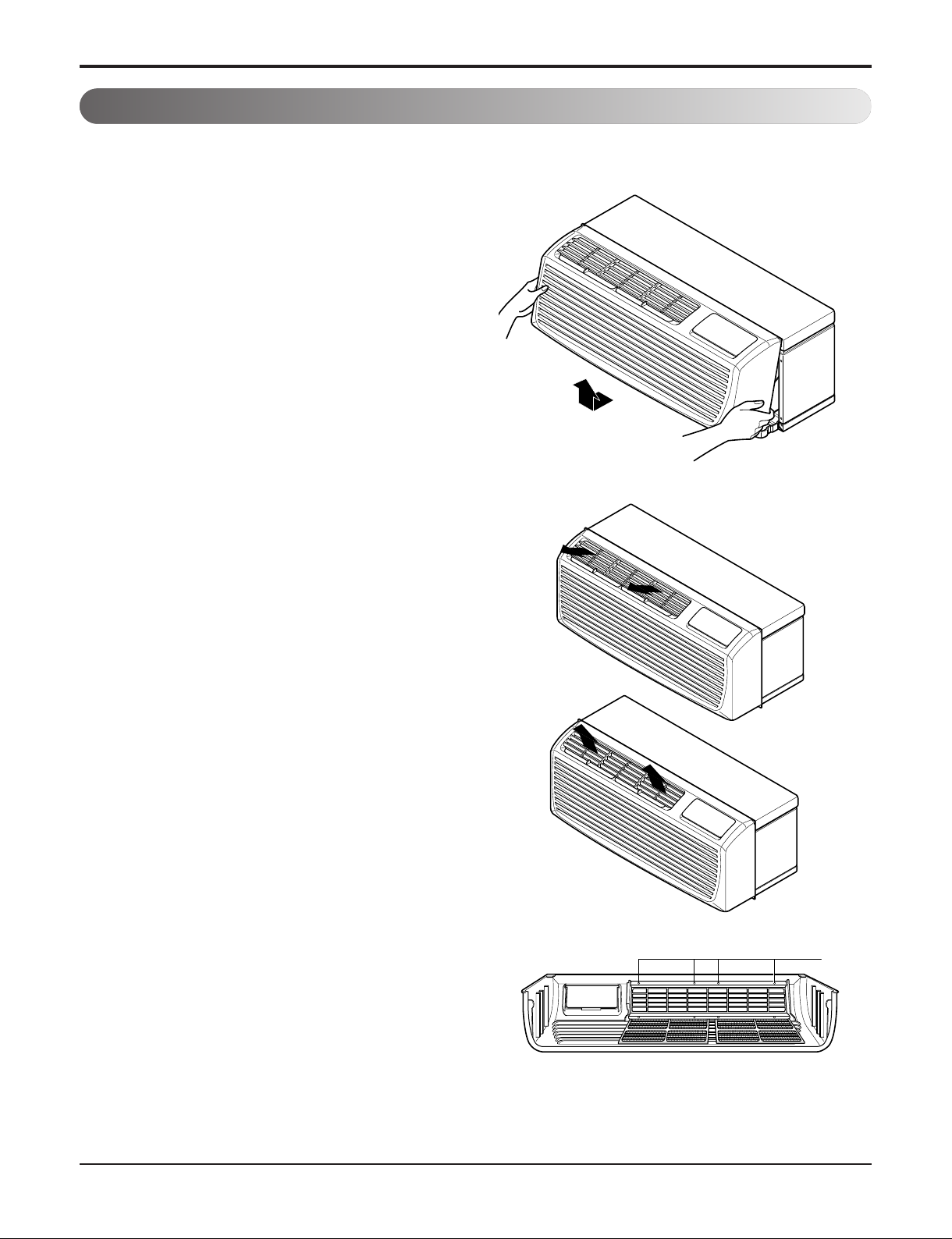
• Indoor Filters
The unit uses two indoor filters which slide in and cut easily. The filters may be cleaned by washing and brushing without
removing the front grille.
• Rotary Compressor
The unit uses a rotary compressor for quiet, reliable operation and long life.
• 2 Position Discharge Grille
The discharge grille can provide air flows upward at an angle of 40 off vertical or 15 degree off vertical. The angle is changed
by removing the front grille and 4 screws that fasten the discharge grille to the front grille and rotating the louvers to an
alternate position.
• Indoor Room Freeze Protection
When the unit senses the room temperature falls to less than 40° F the unit activates the fan motor and either the electric
resistance heater or the hydronic heater to prevent pipes or fixtures from freezing. This also overrides front desk control of the
unit mounted or wall mounted controls.
• Door Switch/Occupancy Sensor
The unit is capable of accommodating a field installed door switch and occupancy sensor to operate the energy management
feature. For additional information, refer to the unit operation section.
• Compressor Overload Protection
This feature prevents the damage of the compressor by sensing the indoor tube temperature in heating. If the indoor
temperature is over 130˚ F, the outdoor fan will be switched off and back on when the temperature drops below 120˚ F.
• Outdoor Air Temperature Switchover
This will effectively change the unit from heat pump mode to total electric resistance heat.
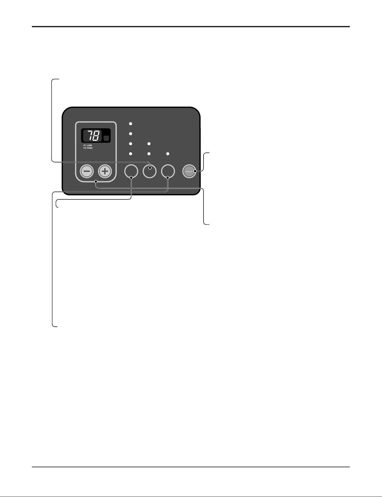
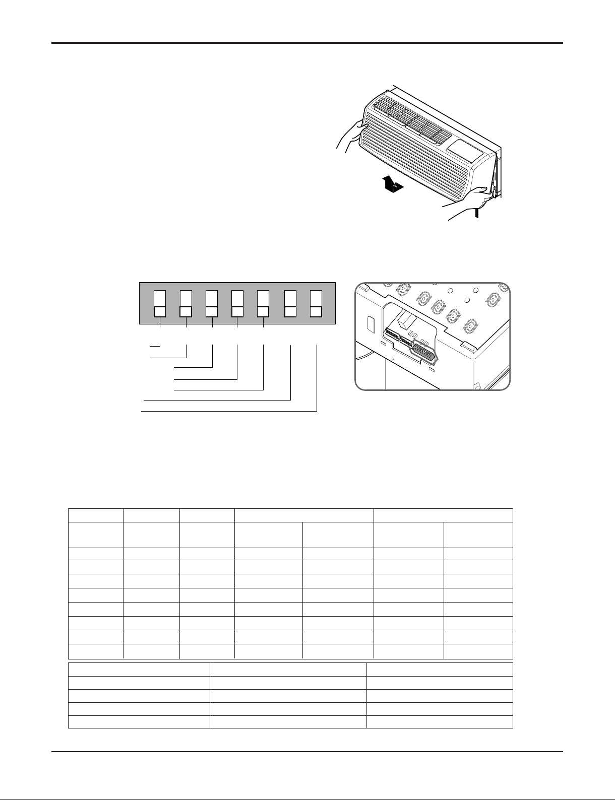
• Temperature limits
The unit is programmed to provide both heating and cooling temperature limits by dip switches on control panel from 50˚ F to
90˚ F. Temperature limits help to prevent overheating and overcooling and reduce energy costs.
• Condensate Drain Valve
The unit has a condensate drain valve to prevent water from collecting or freezing in the basepan.
• Quick Heater Recovery
The unit is designed to operate the electric heater to warm the room to the temperature set point as soon as heat pump cycle
is on in heating. This feature has an advantage of reducing the time to reach the set point and improving the temperature
increase for better comfort.
• Reverse Cycle Defrosting - (PTHP only)
The unit will activate the reverse cycle defrost when the outdoor coil temperature has remained at a cold temperature to form
the ice on the coil.This ice will reduce airflow though the coil and will also reduce the efficiency of unit. The LG PTHP will
employ an active reverse cycle defrost function to melt the ice off the outdoor coil for insuring room comfort conditions and
savings from extended operation.
• High Temperature Heat Pump Operation Protection
The compressor will be switched off to prevent damage when the heat pump is operated in high outdoor temperatures.
• Remote Thermostat Control
Each unit is built to be operated from any standard 4 or 5 wire remote-mounted thermostat, if desired. The unit has a built-in
low voltage power source which can accommodate a large variety of thermostat choices-manual, auto changeover, or
programmable. A remote thermostat can also be added to any installed unit.
• Zone Sensor
Occupants enjoy ultimate comfort with consistent climate control. Attach an optional, inexpensive remote Zone Sensor to
exactly match the functions of the PTAC without disabling any features.
• High Pressure limit
The compressor will be switched off to prevent damage by sensing high pressure [41.8 kgf/cm2G, (595 lbf/in2G)] when the unit
is operated in high outdoor temperatures or blocked outdoor inlet.


 null")