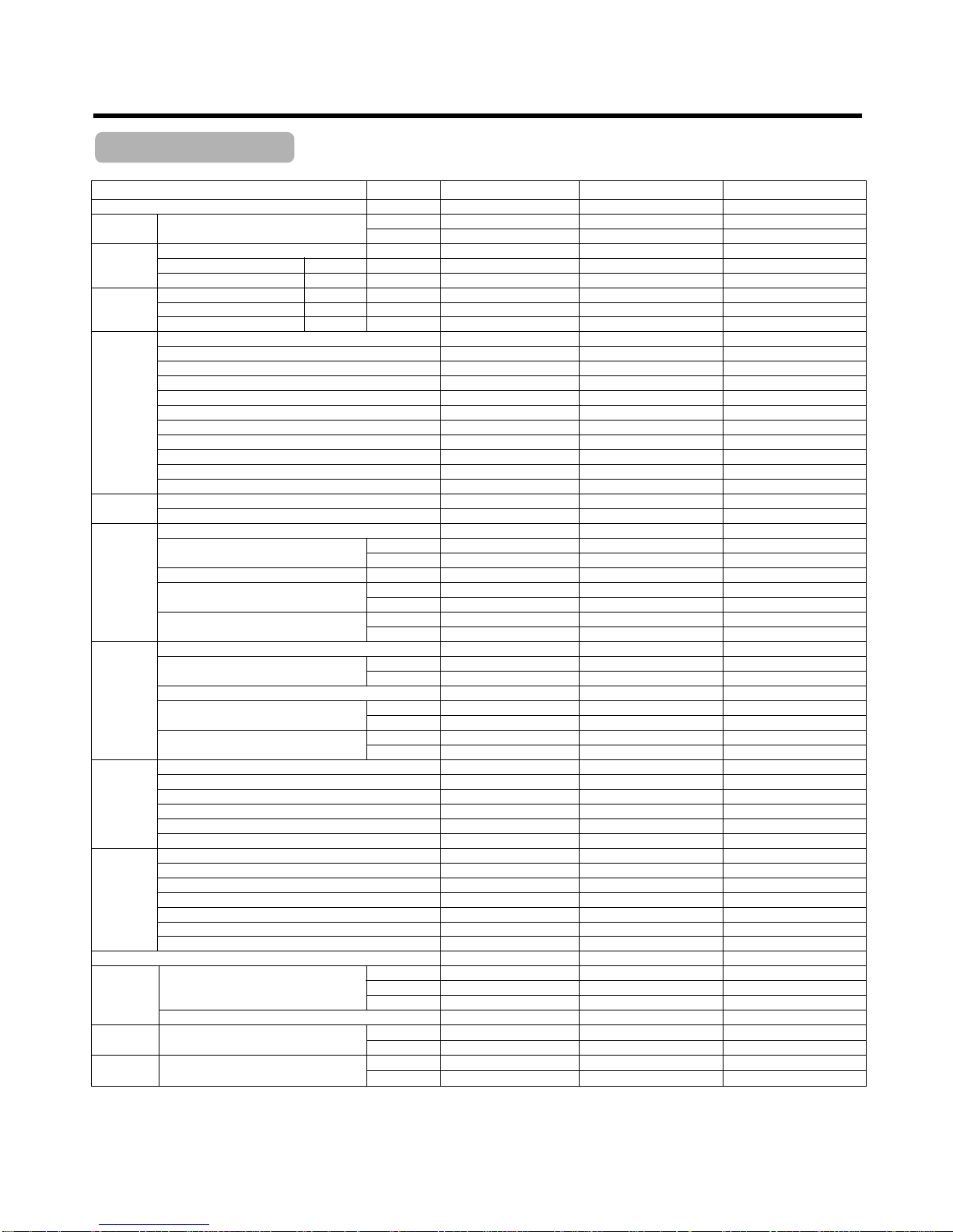
LG LK-0329CH/AH User manual

Single Packaged
Air Conditioner
SERVICE MANUAL
MODELS: LK-0329CH/AH
LK-0429CH/AH
LK-0529CH/AH
LK-SM-101

— 2 —
Contents
Model Number Nomenclature...............................................................................................3
General Data ..........................................................................................................................4
Dimensions............................................................................................................................5
Refrigerant Circuit Diagram..................................................................................................6
Wiring Diagram......................................................................................................................7
Troubleshooting Guide .........................................................................................................8
Features of Controller.........................................................................................................14
Exploded View and Replacement Parts List.....................................................................15
Specification of Components.............................................................................................18

— 3 —
LK-0529CH
Development Sequence
LG
Single Package Air Conditioner
H: Horizontal Flow
C: Cooling Only
A: Gold Fin + Cooling Only
2 : 220V, 60Hz, 1Ø
03 : 3 ton 04 : 4 ton 05 : 5 ton
Nominal cooling capacity
Model Number Nomenclature

—4 —
General Data
Table-1
Nominal ton (Ton) 3 4 5
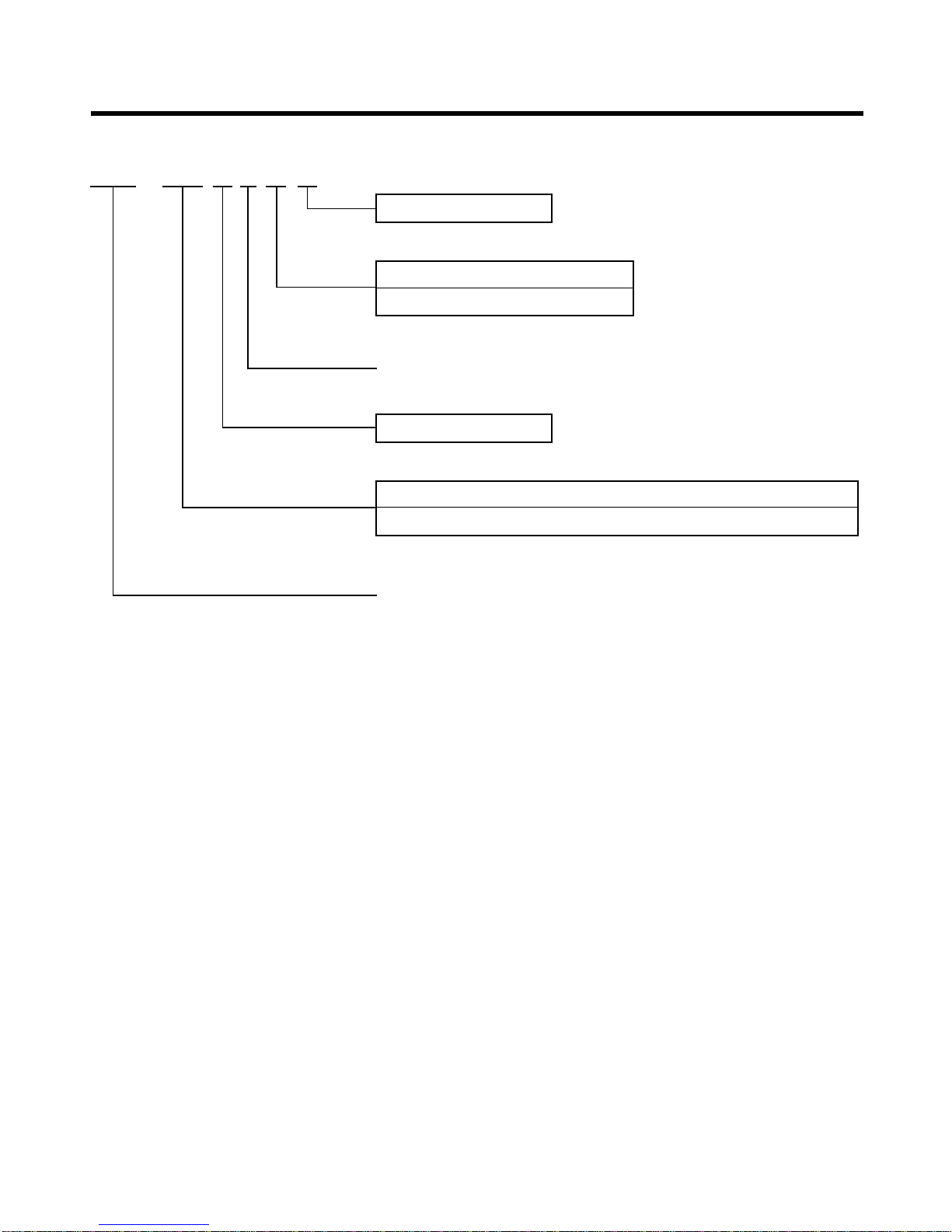
Models LK-0329CH/AH LK-0429CH/AH LK-0529CH/AH
Capacity ARI Net Cooling Capacity (BTU/hr) 35,000 47,000 57,000
(Kcal/h) 8,821 11,845 14,364
Electrical Data
Voltage (V,PH) 208~230V,1PH 208~230V,1PH 208~230V,1PH
M.C.A(with standard motor)
Cooling (Amps) 29 31 48
Power Input Cooling (Watt) 3,740 4,350 6,000
Performance
Air Circulation
Nominal
CFM
CFM 1,050 1,590 1,750
SEER Cooling (BTU/hr.W) 10.0 11.0 10.0
Sound Rating Cooling dB(A) 8 8.4 8.4
Features LG Electronic Thermostat Option Option Option
Time Delay Safety Function
¥¥¥
Cooling Operation Mode
¥¥¥
Heating Operation Mode(with E/Heater)
¥¥¥
Soft Dry Operation - - -
Timer Setting (24-Hour on/off) - - -
Auto restart mode - - -
Humidifier function - - -
Test function - - -
Self-Diagnosis Function - - -
Filter type - - -
Compressor
Type
Scroll Scroll Scroll
Quantity 1 1 1
Outdoor Coil
Type
High efficiency High efficiency High efficiency
Tube size(O.D) (inch) 9/32 9/32 9/32
(mm) 7.00 7.00 7.00
Row/FPI 1R/18FPI 2R/18FPI 2R/18FPI
Lengh (inch) 55 1/8 55 1/8 55 1/8
(mm) 1,400 1,400 1,400
Face area (sq.ft) 10.72 10.72 10.72
(m2) 1.00 1.00 1.00
Indoor Coil
Type
High efficiency High efficiency High efficiency
Tube size(O.D) (inch) 3/8 3/8 3/8
(mm) 9.52 9.52 9.52
Row/FPI 2R/18FPI 3R/18FPI 3R/18FPI
Lengh (inch) 21 5/8 21 5/8 21 5/8
(mm) 550 550 550
Face area (sq.ft) 4.51 4.51 4.51
(m2) 0.42 0.42 0.42
Outdoor Fan
Type Propeller Propeller Propeller
No. Used/Diameter(in.) 1EA/22" 1EA/22" 1EA/22"
Drive Type Direct Direct Direct
CFM 3,500 3,500 3,500
No. Motor/Motor output(Hp) 1/0.33 1/0.33 1/0.33
Motor RPM 1,060 1,060 1,060
Indoor Fan
Type Centrifugal Blower Fan Centrifugal Blower Fan Centrifugal Blower Fan
No. Used 1EA 1EA 1EA
Diameter/Width(in.) 11"/11" 11"/11" 11"/11"
Drive Type/Motor Step Direct/3 Direct/3 Direct/3
No.motors 1EA 1EA 1EA
Motor output(standard/oversized) 0.5Hp/N.A 0.75Hp/N.A 0.75Hp/N.A
Motor rpm(Standard/oversized) 840N.A 1,020/N.A 1,090/N.A
Drain Connection Size(in.)
3/4" 3/4" 3/4"
Refrigerant
(kg) 1.7 2.2 2.3
Refrigerant Charge (lbs) 3.75 4.85 5.07
Type R-22 R-22 R-22
Refrigerant Control Capillary Tube Capillary Tube Capillary Tube
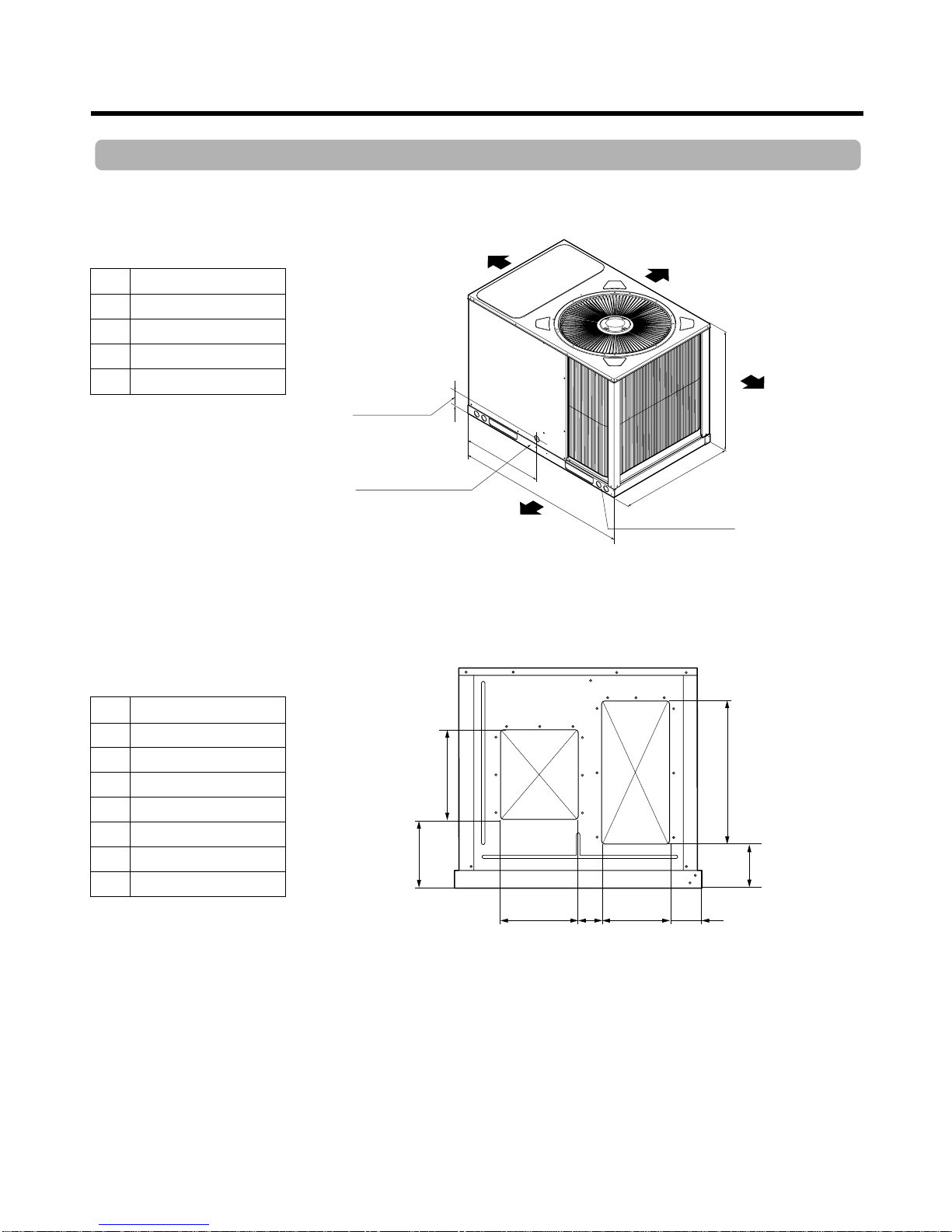
Dimensions
Indoor unit (WxHxD) (inch) 43 3/8*28 9/16*32 11/16 43 3/8*28 9/16*32 11/16 43 3/8*28 9/16*32 11/16
(mm) 1102*725*830 1102*725*830 1102*725*830
Weight Net (kg) 110 120 140
(lbs) 242.5 264.6 308.6

—5 —
Dimensions
LK-0329CH/AH, LK-0429CH/AH, LK-0529CH/AH
A
G
BC D
E
H
SUPPLY
RETURN
F
E
Center line of hole A
B
CLEARANCE 34"
CLEARANCE
48"
(HORIZONTAL)
CLEARANCE
34"
1.5" Dia. hole power wires
1.5" Dia. hole other purpose
CLEARANCE 18"
D
C
Unit : Inch(mm)
Unit : Inch(mm)
A28
9/16 (725)
B32
11/16 (830)
C43
3/8 (1102)
D20
11/16 (525)
E2
7/8(73)
A13
3/16 (335)
B1
1/2(38)
C9
1/2(242)
D3/4(19)
E5
5/8(143)
F24
1/4(622)
G11
9/16 (294)
H9
1/16 (230)

—6 —
Refrigerant Circuit Diagram
SOUTDOOR
COIL INDOOR
COIL
: REFRIGERANT FLOW
PRESSURE
PORT
DISCHARGE
LINE
SUCTION
LINE
LOW-PRESSURE
SWITCH
PRESSURE
PORT
D
CAPILLARY
TUBE
LK-0329CH/AH, LK-0429CH/AH, LK-0529CH/AH

—7 —
Wiring Diagram
DIAGRAM WIRING(WITH LG'S THERMOSTAT)
DIAGRAMWIRING(WITH LOCALLY PURCHASED THERMOSTAT)
1Ø208~230V,60Hz
POWER SUPPLY
USING
ELECTRIC
HEATER
TERMINAL BLOCK
ELECTRIC HEATER
MAGNETIC
CONTACT
(For E/heater)
MAGNETIC
CONTACT
(For comp)
FUSE
(250V, 10A)
LOW PRESSUTRE
SWITCH
TRANS
FACTORY WIRING
OPTIONAL WIRING
FIELD WIRING
BK:BLACK
BR:BROWN
BL:BLUE
T/B :TERMINAL BLOCK
OR:ORANGE
RD:RED
WH:WHITE
YL:YELLOW
NOTES
(AC 24V)
THERMISTER
FOR EVA
(OPTION)
CUT "X"POINT OF WIRE
AND CONNECT THERMISTER
WIRE ON THE EVAPORATOR(OPTION)
EH
ELECTRIC HEATER
EH
A
A
B
B
CAPACITOR
CAPACITOR
POWER RELAY
(For I/motor)
COMP
MOTOR
(OUT)
MOTOR
(IN)
CSR
T1
T1
BK
BK BK
YL
T/B
#4
T/B
#1 T/B
#2
T/B
#3
a
c
b
RD
"X"
BK
BL
BL
BK YL
OR
BK YLOR
RD
OR
BR
YL
OR
BL
RD
RD
RD
RD
BK
BK
WH
1
2AC 24V
AC 24V
MODEL
3RT/4RT
5RT
BLACK
BLUE
BLUE
BLACK
RED
RED
ab
P/NO:3854A30047S
c
MODEL
3RT/4RT
5RT
BLACK
BLUE
BLUE
BLACK
RED
RED
ab
P/NO:3854A30047S
c
L (R)
(C)
(G)
(Y1)
(W1)
N
1
2
3
Fan
Comp
Heater
LG'S THERMOSTAT
3
4
5
6
YL
WH
WH
L1 L2
L1 L2
4
61
0
T2
T2
1Ø208~230V,60Hz
POWER SUPPLY
(L) (N)
1Ø208~230V,60Hz
POWER SUPPLY 1Ø208~230V,60Hz
POWER SUPPLY
USING
ELECTRIC
HEATER
TERMINAL BLOCK
MAGNETIC
CONTACT
(For E/heater)
A
B
T1
L1 L2
T2 MAGNETIC
CONTACT
(For comp)
A
B
T1
L1 L2
40
1
6
T2
CAPACITOR
HCF
COMP
CSR
RD
BK
BKOR
WH
WH
HCF
YL
MOTOR
(OUT)
BK YLOR
OR BL
FUSE
(250V, 10A)
LOW PRESSUTRE S/W
POWER RELAY
(For /Imotor)
TRANS TIME DELAY P.C.B
BK BL
BL
RD YL BK
RD
RD
RD RD
BK
WH
BK
YL
T/B
#1 T/B
#2
T/B
#3
BK
BL
BL
CAPACITOR
MOTOR
(IN) a
c
b
BR
YL
OR
FACTORY WIRING
OPTIONAL WIRING
FIELD WIRING
BK:BLACK
BR:BROWN
BL:BLUE
T/B :TERMINAL BLOCK
OR:ORANGE
RD:RED
WH:WHITE
YL:YELLOW
NOTES
THERMISTER
FOR EVA
(OPTION)
CUT "X"POINT OF WIRE
AND CONNECT THERMISTER
ON THE EVAPORATOR(OPTION)
"X"
1
2
AC 24V
L
N
1
2
3
R
G
Y
W
Fan
Comp
Heater
AC 24V
AC 24V
Fan
Comp
Heater
ELECTRO-MECHANICAL
THERMOSTAT
MECHANICAL
THERMOSTAT
3
4
5
6
(L) (N)
LK-0329CH/AH, LK-0429CH/AH, LK-0529CH/AH

Troubleshooting Guide
—8 —
Ineffective Cooling or Heating
Check of outdoor coil
(heat exchanger) & the fan
operation.
Check gas leakage.
Repair gas leak.
Replacement of unit if the
unit is beyond repair.
Satisfactory operation with
temperature difference of
inlet & outlet air ;
COOLING : 7~10°C
HEATING : 15~17°C
Check heat load increase in
cooling operation.
Unexpected residue
Added electrical utencil
Check of inside gas
pressure.
Adjust refrigerant
charge.
Malfunction of compressor.
Replacement of
compressor
Check of cold (warm) air cir-
culation for smooth flow.
Dirty indoor coil
(heat exchanger.)
Malfunction of fan.
Clogging of air filter.
Obstruction at air outlet.
Countermeasure against
above trouble.
Check clogging in refrigera-
tion circuit.
Repair clogging in refrigera-
tion circuit.
In general, possible trouble is classified in two causes.
The one is called Starting Failure which is caused from an electrical defect, and the other is Ineffective Air
Conditioning caused by a defect in the refrigeration circuit and improper application.
Unit runs but ineffective cooling

—9 —
Troubleshooting Guide
Fails to Start
Check of circuit breaker
and fuse.
Check control switch.
Fan only fails to start.
Improper wiring.
Defect of fan motor
capacitor.
Defect of compressor
capacitor.
Irregular motor resistance
( Ω
)
Irregular motor insulation
( Ω
)
Replacement of fan motor.
Improper electric heater
Replacement of electric
heater.
Regular but fails to start.
Replacement of compressor.
Electric heater is not energized
Loose terminal connection.
Improper wiring
Irregular motor resistance ( Ω
)
Irregular motor insulation ( Ω
)
Replacement of compressor
Drop of power voltage.
Capacitor check.
Replacement of capacitor.
Compressor only fails to
start.
Check power source.
Check control switch
setting.

—10 —
PACKAGE AIR CONDITIONER VOLTAGE LIMITS
1. No cooling and heating operation performed
1) Both the blower and the compressor do not work
NAME PLATE RATING MINIMUM MAXIMUM
208~230V 187V 253V
2) Only Indoor blowers do not work
WHAT TROUBLED COMPLAINTS HOW TO CHECK REMEDY
Other parts except the
unit
Magnetic switch for com-
pressor & fan motor
Operating switch
•Electric supply interrupted
•Defective power wiring
•Cut off power fuse
Too low voltage
Control point is on condi-
tion of "OFF" due to trou-
ble.
Troubled or defective
contactor
Measure power supply
with a tester in case that
the same power source is
supplied to other equip-
ment except the unit,
what and where troubled
can be discovered by
checking the operation of
other equipment.
Measure it with a tester.
Make short-circuit, then
measure it with tester.
Check it with the eyes or
tester.
•Repair a switch box and
relative instrument.
•Replacement of fuse
•Request a power
supplier to repair.
Check the power source.
Use a thick cable if nec-
essary.
Replace it if necessary.
Repair or replace it.
WHAT TROUBLED COMPLAINTS HOW TO CHECK REMEDY
Motor
Capacitor
Electric wiring
•Over heated
•Wiring short
Defected
•Cut- OFF of wiring
•Short circuited on
operation
Check it with tester
Check it with a tester.
Repair or replace it.
Replace it.
Rewiring or Repair.
Troubleshooting Guide

—11 —
3) Only outdoor fan does not work
WHAT TROUBLED COMPLAINTS HOW TO CHECK REMEDY
Motor
Electric Wiring
•Over-heated
•Wire short
Cut off of wiring
Short circuited on
operation
Check how it is insulated.
Check it with a tester.
Repair or replace it.
Rewiring or repair.
4) Only compressor does not work
WHAT TROUBLED COMPLAINTS HOW TO CHECK REMEDY
Magnetic switch for
compressor motor
Compressor motor
High pressure switch
(Option part)
Electric circuit
Defective contact,
magnetic coil troubled.
Troubled over-heated
(layer short)
Troubled or defective
contact or operating
Defective connection or
disconnection of the circuit
for compressor.
Check it with the eyes on
with a tester.
Check how it is insulated.
Check it with a tester.
Repair or replace it.
Replace or repair the
compressor.
Replace it if neces-
sary.
Rewiring or push reset
button.
Troubleshooting Guide

—12 —
Note: Use an appropriate measuring instrument for readjustment.
*1: High-pressure switch moves.
*2: Low- pressure switch moves.
2. The Units discontinue after the operation started
WHAT TROUBLED COMPLAINTS HOW TO CHECK REMEDY
Outdoor coil
In-condensable gas
blended.
High pressure switch
(Option part)
Refrigerant
Outdoor Fan
Coil is dirty *1
Air intruded into the
refrigerant pipe line *1
Improper adjustment
A shortage of refrigerant
amount. * 2 Check pressure
Reverse rotation of fan
Obstacle
Air short circuit *1
Checking
In the event that
difference between the
saturating temperature
corresponding to high
pressure and the
temperature of air
discharged from the
outdoor coil is more than
15°C, incondensable gas
may be blended.
Check it with a pressure
gauge.
Confirm the wind blowing
out upward.
Check it with eyes.
Wash it by means of
something like chemical
washing.
Extract air by vacuum
pump, then replenish
(charge) the refrigerant.
Read just it to normal
operating pressure.
(Note)
Don't alternate the
specified adjusting
pressure. If the adjusted
pressure exceed the
specified range, it will
cause a great accident.
Replenish the
refrigerant. Repair the
spot where it is leaked.
If reversed, connect
interchanged wires to
each terminal.
Power wirings.
Troubleshooting Guide

—13 —
3. The unit is working, but not cooling and heating sufficiently
(Both blower and compressor are working)
WHAT TROUBLED COMPLAINTS HOW TO CHECK REMEDY
Load
Air flow
Short air volume
Refrigerant
Air passage
Air filter
Much Cooling or Heating
load
Obstacle disturbs Intake
of uniform airflow.
Reverse rotation of
blower.
Shortage in the charged
refrigerant.
Improper or foreign bodies
Clogged with dust
Heat load increased.
Window or door has many
cracks or gaps.
Checking
Checking
Coil inlet pipe is frosted
Checking
Checking
Do necessary disposal
respectively.
Correct it.
Correct it.
Recharge it.
(Repair the leakage spot).
Correct or clear the
foreign bodies.
Cleaning
4.
All the functions are performed as specified, but very noisy and vibrant
WHAT TROUBLED COMPLAINTS HOW TO CHECK REMEDY
Compressor
Blower
Screws
Electric troubles
(Magnetic contactor)
Others
•Checking
Checking
Checking
Checking
Improper installation Checking
•Replace the
compressor
Repair or replace it.
Clear the foreign bodies.
Correct
Repair and clean or
replace it.
Correct it.
Liquid refrigerant flooding
back from the evaporator.
Faulty Discharge valve
and suction valve.
Fan broken.
Foreign matters intruded.
Looseness or fail-off of
screws
Defective contact.
Defective contact point.
Rusting and foreign mat-
ters in the iron core con-
tact face. Defective con-
tact of the
operating switch.
•Check for refrigerant over-charge.
•Check to see if the intake air temperature is
extremely cold.
•Check for insufficient air flow quantity.
Troubleshooting Guide

—14 —
Features of Controller
12V
12V
L1
L2
L3
12V
R03M
220K R01M
47K R06M
1K Q01M
KRC107K DO1M
1N4148
RY01M
JQ1a-12V
ZNR
INR14D471
TRANS
RY01M
JQ1a-12V
Magnetic
Relay
AC220V
60Hz
R02M
47K IC01M
KA393
D04D
10 D02D
D05D
C02D
104
C04D
104
IC01D
7812
C01D
470uF
25V
D03D
D02D~D05D
1SR139-600
3
8
1
+
-
2
4
C01M
3.3uF
+
+
IC2
C7
IC1 C1 CN1
CN2
D1
D2
D3
D4
D5
C4
RY1
R5
R8
R9
R6
D6
C6
C8
R7
D7
R3
R2
C2
R4
R1
R10
PCB: 2Q01062A
C3
C5
Q1
Q2
IC3
CN3
1. Timer PCB Circuit Diagram
2. Timer PCB ASSY

—15 —
Exploded View and Replacement Parts List
268716
W0CZZ-1
261704
W0CZZ-2
669200
666000
249950
1. LK-0329CH/AH, 0429CH/AH, 0529CH/AH
• Exploded View

—16 —
Exploded View and Replacement Parts List
559010
554160
346810
546810
554031
552111
354210
359012
330870

—17 —
Exploded View and Replacement Parts List
Replacement Parts List
249950 CONTROL BOX ASSY, SINGLE 4995A10060B 4995A10060B 4995A10060A 4995A10060A 4995A10060E 4995A10060E R
261704 TRANSFORMER, POWER 6170A10001E 6170A10001F 6170A10001E 6170A10001F 6170A10001E 6170A10001F R
268716 TIMER 3Q010117C 3Q010117C 3Q010117C 3Q010117C 3Q010117C 3Q010117C R
346810 MOTOR ASSY, INDOOR 4681A20057C 4681A20057C 4681A20057B 4681A20057B 4681A20057B 4681A20057B R
354210 EVAPORATOR ASSY, FIRST 5421A10002T 5421A10002T 5421A10002S 5421A10002S 5421A10002S 5421A10002S R
359012 FAN ASSY, BLOWER 2A00578V 2A00578V 2A00578V 2A00578V 2A00578V 2A00578V R
546810 MOTOR ASSY, OUTDOOR 4681A20039B 4681A20039B 4681A20039B 4681A20039B 4681A20039B 4681A20039B R
554031 CONDENSER ASSY, BENT 5403A10021A 5403A10021B 5403A10019A 5403A10019B 5403A10019A 5403A10019B R
554160 COMPRESSOR ASSY, FINAL 2520UFDK1AA 2520UFDK1AA 2520UFJK1AA 2520UFJK1AA 5416A10002B 5416A10002B R
559010 FAN ASSY, PROPELLER 5901A10010A 5901A10010A 5901A10010A 5901A10010A 5901A10010A 5901A10010A R
566000 SWITCH, PRESSURE 6600A20004D 6600A20004D 6600A20004D 6600A20004D 6600A20004D 6600A20004D R
666000 SWITCH, MAGNET 2A00771F 2A00771F 2A00771F 2A00771F 2A00771F 2A00771F R
669200 RELAY 6920AP3194B 6920AP3194B 6920AP3194B 6920AP3194B 6920AP3194B 6920AP3194B R
W0CZZ-1 CAPACITOR, DRAWING 0CZZA20001B 0CZZA20001B 0CZZA20001B 0CZZA20001B 0CZZA20001B 0CZZA20001B R
W0CZZ-2 CAPACITOR, DRAWING 6120AR2194K 6120AR2194K 6120AR2359U 6120AR2359U 0CZZA10001A 0CZZA10001A R
552111 TUBE ASSY, CAPILLARY 5211A10268A 521110250A 5211A10270A R
5211A10268B(WITH TROPICAL CYCLE) 5211A10268B(WITH TROPICAL CYCLE)
-R
330870 DRAIN PAN ASSY 3087A10017A R
3828A20228A(SPANISH WITH NOM) R
3828A20228B(ENGLISH) R
738290 OWNERS MANUAL 3828A20228C(SPANISH + ENGLISH) R
3828A20228G(ENGLISH +ARABIC) R
3828A20228L(SPANISH FOR MIRAGEL) R
738281 SERVICE MANUAL 3828A20220B 3828A20220B 3828A20220B 3828A20220B 3828A20220B 3828A20220B R
267110 REMOTE CONTROLLER 6711A20063A(OPTION PART) R
ASSEMBLY
267110 REMOTE CONTROLLER 6711A20041R(OPTION PART) R
ASSEMBLY(WIRELESS)
LOCATION
DESCRIPTION P/NO.
REMARKS
NO.
LK-0329CH LK-0329AH LK-0429CH LK-0429AH LK-0529CH LK-0529AH

—18 —
Specification of Components
LK-0329CH/AH LK-0429CH/AH LK-0529CH/AH
COMP P/No. 2520UFJK1AA 5416A10002B
Model name SQ032KAA SQ042KAA H20R583ABCA
*RLA 14.0 17.1 28
**LRA 74 102 165
Q'ty 1 1 1
INDOOR MOTOR P/No. 4681A20057C 4681A20057B 4681A20057B
Output 0.5Hp 0.5Hp 0.5Hp
Shaft Dia. 15 mm 15 mm 15 mm
RPM 840(Hi) 1,020(Hi) 1,090(Hi)
OUTDOOR MOTOR P/No. 4681A20039B 4681A20039B 4681A20039B
Output 0.33 Hp 0.33 Hp 0.33 Hp
Shaft Dia. 15 mm 15 mm 15 mm
RPM 1,050 1,050 1,050
Q'ty 1 1 1
OUTDOOR FAN P/No. 5901A10010A 5901A10010A 5901A10010A
Diameter O.D. 560mm O.D. 560mm O.D. 560mm
INDOOR BLOWER P/No. 2A00578V 2A00578V 2A00578V
Diameter*Width 280(mm) ×280(mm) 280(mm) ×280(mm) 280(mm) ×280(mm)
LOW PRESSURE SWITCH P/No. 6600A20004D 6600A20004D 6600A20004D
Spec.
OFF:2.0kgf/cm
2
/ON:3.5kgf/cm
2
OFF:2.0kgf/cm
2
/ON:3.5kgf/cm
2
OFF:2.0kgf/cm
2
/ON:3.5kgf/cm
2
Rated volt. AC 24 AC 24 AC 24
Maker SAGINOMIYA SAGINOMIYA SAGINOMIYA
CAPACITOR for COMP. P/No. 6120AR2194K 6120AR2359U 0CZZA10001A
Spec. 45µF/400VAC 60µF/400VAC 55µF/400VAC
CAPACITOR for ***IDM. P/No. 0CZZA20001B 0CZZA20001B 0CZZA20001B
Spec. 15µF/450VAC 15µF/450VAC 15µF/450VAC
CAPACITOR for ****ODM. P/No. 6120AR2194K 6120AR2359U 0CZZA10001A
Spec. 6µF/400VAC 6µF/400VAC 6µF/400VAC
CAPILLARY TUBE P/No. 3E92334G 3E92334M 3H02633K
Spec. ID 1.4 ×L1200(mm) ID 1.4 ×L1000(mm) ID 1.4 ×L750(mm)
Q'ty 5 8 8
TRANSFORMER P/No. 6170A10001E 6170A10001E 6170A10001E
Spec. AC220V, 450mA AC220V, 450mA AC220V, 450mA
CONTACTOR for COMP. P/No. 2A00771F 2A00771F 2A00771F
Spec. 40A, 24V CONTROL 40A, 24V CONTROL 40A, 24V CONTROL
RELAY for IDM. P/No. 6920AP3194B 6920AP3194B 6920AP3194B
Spec. AC 24V, 25A AC 24V, 25A AC 24V, 25A
RELAY for ODM. P/No. 2A00771F 2A00771F 2A00771F
Spec. 40A, 24V CONTROL 40A, 24V CONTROL 40A, 24V CONTROL
*RLA : RATED LOAD AMPERE
**LRA : LOCKED ROTOR AMPERE
***IDM : INDOOR MOTOR
****ODM : OUTDOOR MOTOR

P/No.: 3828A20220B May, 2002
Printed in Korea
This manual suits for next models
2
Table of contents
Other LG Air Conditioner manuals
Popular Air Conditioner manuals by other brands

TemperZone
TemperZone OSA 840RKTB installation guide

Mitsubishi Electric
Mitsubishi Electric PLA-SP BA Series Operation manual

air choice
air choice TY-EA-03 user manual

GE
GE AHE18 Series Owner's manual and installation instructions

Gree
Gree GSW12-22L/B Technical & service manual

Frigicoll
Frigicoll MKD-V300 Installation & owner's manual