LG MLP-F8081CL User manual

LG
Floor Standing Type
Air Conditioner
SERVICE MANUAL
LG
CAUTION
website http://www.lgservice.com
e-mail http://www.lgeservice.com/techsup.html
• BEFORE SERVICING THE UNIT, READ THE SAFETY
PRECAUTIONS IN THIS MANUAL.
• ONLY FOR AUTHORIZED SERVICE PERSONNEL.
MODEL: MLP-F8081CL/AL/HL/BL/ZL
LP-C808FA0/LP-H808FA0/LP-Z808FA0

2Floor Standing Type Air Conditioner
Floor Standing Type Air Conditioner Service Manual
TABLE OF CONTENTS
Safety Precautions....................................................................................................................................3
Functions...................................................................................................................................................7
Product Specifications.............................................................................................................................9
Dimensions..............................................................................................................................................10
Wiring Diagram........................................................................................................................................11
Operation Details ....................................................................................................................................16
Installation...............................................................................................................................................22
Operating.................................................................................................................................................36
3-Way Valve..............................................................................................................................................37
Troubleshooting Guide...........................................................................................................................45
Electronic Control Device ......................................................................................................................58
Schematic Diagram.................................................................................................................................61
Exploded View and Replacement Parts List.........................................................................................62

Service Manual 3
Safety Precautions
Safety Precautions
To prevent injury to the user or other people and property damage, the following instructions must
be followed.
■Incorrect operation due to ignoring instruction will cause harm or damage. The seriousness is
classified by the following indications.
■Meanings of symbols used in this manual are as shown below.
This symbol indicates the possibility of death or serious injury.
This symbol indicates the possibility of injury or damage to properties only.
■Installation
Be sure not to do.
Be sure to follow the instruction.
Do not use a defective or under-
rated circuit breaker. Use this
appliance on a dedicated circuit.
• There is risk of fire or electric
shock.
Always ground the product.
• There is risk of fire or electric
shock.
Install the panel and the cover
of control box securely.
• There is risk of fire or electric
shock.
Always install a dedicated cir-
cuit and breaker.
• Improper wiring or installation may
cause fire or electric shock
Use the correctly rated break-
er or fuse.
• There is risk of fire or electric
shock.
Do not modify or extend the
power cable.
• There is risk of fire or electric
shock.

4Floor Standing Type Air Conditioner
Safety Precautions
■Operational
Do not install, remove, or re-
install the unit by yourself
(customer).
• There is risk of fire, electric shock,
explosion, or injury.
Be cautious when unpacking
and installing the product.
• Sharp edges could cause injury.
Be especially careful of the case
edges and the fins on the con-
denser and evaporator.
For installation, always con-
tact the dealer or an
Authorized Service Center.
• There is risk of fire, electric shock,
explosion, or injury.
Do not install the product on a
defective installation stand.
• It may cause injury, accident, or
damage to the product.
Be sure the installation area
does not deteriorate with age.
• If the base collapses, the air condi-
tioner could fall with it, causing
property damage, product failure,
and personal injury.
Do not let the air conditioner
run for a long time when the
humidity is very high and a
door or a window is left open.
• Moisture may condense and wet or
damage furniture.
Do not touch(operate) the
product with wet hands.
• There is risk of fire or electrical
shock.
Do not place a heater or other
appliances near the power
cable.
• There is risk of fire or electric
shock.
Do not let electric parts of the
product get wet.
• There is risk of fire, failure of the
product, or electric shock.

Service Manual 5
Safety Precautions
■Installation
Do not open the inlet grill of the product during
operation. (Do not touch the electrostatic filter,
if the unit is so equipped.)
• There is risk of physical injury, electric shock, or prod-
uct failure.
Be cautious that water could not enter the
product.
• There is risk of fire, electric shock, or product damage.
Always check for gas (refrigerant) leakage after
installation or repair of product.
• Low refrigerant levels may cause failure of product.
Install the drain hose to ensure that water is
drained away properly.
• A bad connection may cause water leakage.
Do not store or use flammable gas or com-
bustibles near the product.
• There is risk of fire or failure of product.
If strange sounds, or small or smoke comes
from product. Turn the breaker off or discon-
nect the power supply cable.
• There is risk of electric shock or fire.
Gasolin

6Floor Standing Type Air Conditioner
Safety Precautions
Keep level even when installing the product.
• To avoid vibration or water leakage.
Use two or more people to lift and transport
the product.
• Avoid personal injury.
Use a soft cloth to clean. Do not use harsh
detergents, solvents, etc.
• There is risk of fire, electric shock, or damage to the
plastic parts of the product.
Do not touch the metal parts of the product
when removing the air filter. They are very
sharp!
• There is risk of personal injury.
Do not step on or put anyting on the product.
(outdoor units)
• There is risk of personal injury and failure of product.
Do not insert hands or other objects through
the air inlet or outlet while the product is oper-
ated.
• There are sharp and moving parts that could cause
personal injury.
90˚
Wax
Thinner
■Operational

Service Manual 7
Functions
Functions
Indoor Unit
Power Switch ON/OFF
Operation Mode Control
Sensing the room temperature
Controlling the room temperature
Starting Current Control
Sensing Heat Exchanger Temperature
Timer Delay Safety Control
Indoor Fan Speed Control
Operation Indication lamps
Temperature Setting
Airflow Direction Control
Room temperature Display
Timer Control
•Cooling, Soft Dry, Auto, Fan ➔ Cooling Model •
Cooling, Heating, Soft Dry, Fan
➔
Heat Pump Model
•Room temperature sensor (Thermistor)
•Maintains the room temperature in accordance with the setting temperature.
•Indoor fan is delayed for 3 sec at the starting.
•Heat exchanger temperature sensor (Thermistor)
•Restarting is inhibited for approx. 3 minutes.
•High, Low, Duct
•Up : up to 30°C
•Down : down to 16°C
•Airflow direction Manual control
•Low, 10°~ 35°C, Hi
•Off Timer (1, 2, 3....7 hour)

8Floor Standing Type Air Conditioner
Functions
Outdoor Unit
Deice Control
Outdoor Fan Speed Control
Sensing Heat Exchanger Temperature
•De-ice PCB
•One speed
•Heat exchanger temperature sensor (Thermistor)

Service Manual 9
Product Specifications
POWER SOURCE (ø, V, Hz)
COOLING CAPACITY Btu/h
W
INPUT W
CURRENT A
HEATING CAPACITY Btu/h
(W)
W
(W)
INPUT W
(W)
CURRENT A
(A)
MAKER
TYPE
COMPRESSOR MODEL
INPUT W
CURRENT A
CAPACITY kcal/h
NOISE INDOOR dB(A)
LEVEL(1m) OUTDOOR
AIR INDOOR CMM
VOLUME OUTDOOR
REFRIGERANT R-22 kg
HEAT INDOOR R/C/FPI
EXCHANGER OUTDOOR R/C/FPI
FAN INDOOR TYPE
OUTDOOR
ROOM TEMPERATURE CONTROL
NET INDOOR kg
WEIGHT OUTDOOR
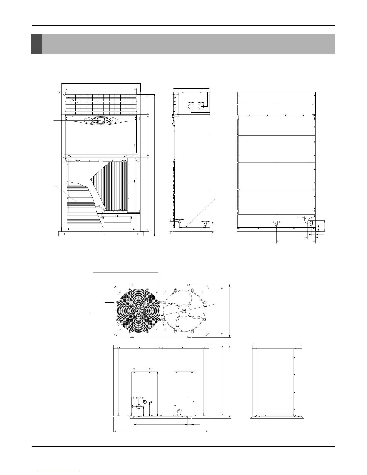
DIMENSIONS INDOOR mm
(W × H × D) OUTDOOR
SVC LIQUID Inch
VALVE GAS (mm)
3,380 – 415,50 3,380 – 415,50 3,380-415,50 3,380-415,50 3,380-415,50
71,400 71,400 75,000 75,000 75,000
20,927 20,927 21,995 21,995 21,995
6,900 7,000 8,300 8,000 8,000
12.0 13.0 14.0 13.5 13.5
– 74,000 – 80,000 80,000
(8,000) (8,000)
– 21,680 – 23,460 23,460
(8,000) (8,000)
– 6,500 – 7,400 7,400
(8,000) (8,000)
– 12.5 – 13.0 13.0
(12.0) (12.0)
COPELAND COPELAND LG LG LG
SCROLL SCROLL SCROLL SCROLL SCROLL
ZR94KC – TFD ZR94KC – TFD SB061Y/SQ042Y SB061Y/SQ042Y SB061Y/SQ042Y
6,990 6,990 4,660/3,064 4,660/3,064 4,660/3,064
13.6 13.6 8.3/5.7 8.3/5.7 8.3/5.7
19,732 19,732 12,801/8,489 12,801/8,489 12,801/8,489
56 56 60 60 60
65 65 65 65 65
57 57 57 57 57
150 150 150 150 150
5.9 7.2 6.6 8.44 8.44
3/33/17 3/33/17 3/33/17 3/33/17 3/33/17
2/18/17 2/18/17 (2/18/17) X2 (2/18/17) X2 (2/18/17) X2
SIRROCO SIRROCO SIRROCO SIRROCO SIRROCO
PROPELLER PROPELLER PROPELLER PROPELLER PROPELLER
MICOM CONTROL MICOM CONTROL MICOM CONTROL MICOM CONTROL MICOM CONTROL
132 132 110 110 110
150 150 150 150 150
1,050 x 1,880 x 495 1,050 x 1,880 x 495 1,050 x 1,880 x 495 1,050 x 1,880 x 495 1,050 x 1,880 x 495
1,000
×
965
×
370 1,000
×
965
×
370
1,245 x 930 x 650 1,245 x 930 x 650 1,245 x 9
30 x 650
5/8 (15.88) 5/8 (15.88) 5/8 (15.88) 5/8 (15.88) 5/8 (15.88)
1 (25.4) 1 (25.4) 1 (25.4) 1 (25.4) 1 (25.4)
MODEL
LP-F8081CL/AL LP-F8081HL/BL
LP-F8081ZL LP-C808FA0 LP-H808FA0 LP-Z808FA0
(Including Electric
heater)

Indoor Unit
Outdoor Unit
10 Floor Standing Type Air Conditioner
Dimensions
Dimensions
268568990 1890
1051 496
75
130 121
75
193
951
36 36
60
345
93.8
131
36 75
525
109.5 58.5
145.8
93.8
Air Outlet
Vent
Air Inlet
Vent
Window
Display
Earth
Screw
700
650
963
930
582
185
125
546
1245
700 50
260
95 80
Air Outlet Vent
Air Inlet Vent

Service Manual 11
Wiring Diagram
Model: LP-F8081CL/AL
Wiring Diagram
Indoor & Outdoor Unit Circuit Diagram
INDOOR UNIT CIRCUIT DIAGRAM
OR
BK
BL
RD
BR
YL
RY3
CN2
CN3
DISPLAY
PCB ASM
CN1 RD
GN/YL
CONNECT TO
OUTDOOR UNIT
WH
BK
BK
GN/YL
BL
BR
YL
BL CONNECT TO CONTACT "R" "N" OF
OUTDOOR TERMINAL BLOCK "Tmo1"
NOTE
BL
BK
BR
OR
RD
WH
YL
GN/YL
BLUE
BLACK
BROWN
ORANGE
RED
WHITE
YELLOW
GREEN/YELLOW
:
:
:
:
:
:
:
:
RY3
1
MAIN PCB ASM
RY2 FUSE
(10A)
RY1
SUB PCB ASM
CAPACITOR
INDOOR
FAN MOTOR
ROOM
TH
EVA
TH
2 3 4
3
2
1
Tmo1,2
52C
51C
63H
CH
FMo1,2
Co1,2
TERMINAL BLOCK
MAGNETIC CONTACTOR
EOCR(COMP.)
HIGH PRESSURE SWITCH
CRANKCASE HEATER
OUTDOOR FAN MOTOR
RUN CAPACITOR FOR FAN(OUTDOOR)
NOTE
BL
BK
BR
OR
RD
WH
YL
GN
GN/YL
BLUE
BLACK
BROWN
ORANGE
RED
WHITE
YELLOW
GREEN
GREEN/YELLOW
:
:
:
:
:
:
:
:
:
Tmo1
3Ø, 4W
380-415V, 50Hz
POWER SUPPLY
R S T N OR
Co1
YL BR OR BK YL BR OR BK
BK
OR
BK
BK WH WH RD WH
FUSE(5A)
WH
BK
BR
BL
BK
GN/YL
GN/YL
CH
WH
BK
RD
BK
BK CONNECT TO
INDOOR UNIT
WH
BK
BK
RD
T1 T3 T2
COMP
WH
WH
BK
L1 L2 Tb Ta
Tc
51C
63H Tmo2
1
2
3
4
5
6
FUSE(5A)
CONNECT TO
INDOOR UNIT
Co2
13531
24632
A
B
52C
FIELD WIRING
NOTE
1. This product is 3ø,4W,380-415V,50Hz.
2. "Check List" before test run.
1st: Reconfirm the wiring connecting
of compressor, outdoor unit motor.
2nd: Fasten the screw of "Terminal Block
Tmo1,2" once more.
FMo2FMo1

12 Floor Standing Type Air Conditioner
Wiring Diagram
Model: LP-F8081HL/ZL/BL
INDOOR UNIT CIRCUIT DIAGRAM
CAPACITOR
BR OR
BK
BL
RD
YL
INDOOR
FAN MOTOR
RY3
RY2
RY1
SUB PCB ASM
FUSE
(10A)
DISPLAY
PCB ASM
MAIN PCB ASM
CN1
CN2
ROOM
TH
EVA
TH
CN3
Tmi
YL
BL
3
2
1CONNECT TO CONTACT "T" "N" OF
OUTDOOR TERMINAL BLOCK "A"
Ry3
Ry6
Ry7 BK
BK
BK
TF
TF
BK
BL
BK
BK
WH
RD
POWER SUPPLY
3Ø380~415V
50Hz
L1
L2
L3
a
T1
T2
T3
b
EH
123
456
5
4
Tmi
CONNECT TO OUTDOOR
(HOUSING ASM)
TP
Option part
DEF TH
EH
EVA TH
ROOM TH
Ry3
Ry6
Ry7
THi
Tmi
TP
TF
TERMINAL BLOCK(INDOOR)
BIMETAL SWITCH FOR HEATER
THERMAL FUSE
RELAY FOR COMP
RELAY FOR HEATER
RELAY FOR HEATING
THERMISTOR FOR INDOOR TEMP
THERMISTER FOR DISCHARGE AIR
ELECTRIC HEATER
THERMISTER FOR EVA TEMP.
THERMISTER FOR EVA INDOOR TEMP
NOTE
BK:BLACK
BL:BLUE
BR:BROWN
YL :YELLOW
WH:WHITE
OUTDOOR UNIT WIRING DIAGRAM
R S T N
POWER SUPPLY
3ø,380-415V,50Hz
TERMINAL(4P)
NC
12
34
56
78
NO NC NO
1
2
3
4
5
6
NOTE
BL
BK
BR
OR
RD
WH
YL
GN/YL : GREEN/YELLOW
RED
WHITE
YELLOW
BLUE
BLACK
BROWN
ORANGE
:
:
:
:
:
:
:
CH
F1,2
Co
FMo
D.P
C TH
20SV
49FMo
DEICER PCB
THERMISTOR FOR PIPETEMP.(OUTDOOR)
REVERSING COIL
INERNAL T.P FOR FMo
52F1
63H1
63H2
49C
RELAY FOR FMo
HIGH PRESSURE SWITCH
HIGH PRESSURE SWITCH FOR HEATING
INTERNAL O.L.P FOR COMP.
TM
52C
3.P.D
MAIN TERMINAL BLOCK
MAGNETIC CONTACTOR
3 PHASE DETECTOR
CRANKCASE HEATER
FUSE (250V, 5A)
RUN CAPACITOR FOR FMo
OUTDOOR FAN MOTOR
TM GN/YL
F2
F2
63H1
63H2
RD RD RD
BK
BK
BK
BK
BK 3.P.D
R
AB
ST
BK
WH
RD
RD
52C
BK
BK
WH
WH WH
WH
C TH
D.P
52F1
YL
OR
BL
WH
BK
BK
YL
BK
BL
BR
BL
BR
BL
GN/YL
BL
20SV
13531A
24632B
YL
BR
OR
BK
YL
BR
OR
BK
BK
WH
RD
L1 L2
L3
YL
BR
OR
BK
YL
BR
OR
BK
FMo
49FMo FMo
49FMo COMP

Service Manual 13
Wiring Diagram
Model: LP-C808FA0

14 Floor Standing Type Air Conditioner
Model: LP-H808FA0
Wiring Diagram

Service Manual 15
Model: LP-Z808FA0
Wiring Diagram

16 Floor Standing Type Air Conditioner
Operation Details
Operation Details
(1) The function of main control
1. Time Delay Safety Control
•3min... The compressor is ceased for 3 minutes to balance the pressure in the refrigeration cycle.
(Protection of compressor)
•3sec... The indoor fan is ceased for 1~3 seconds to prevent relay noise.
(Protection of fan relay and micro chip)
•1min... The 4-way valve is ceased for 30 sec. to prevent the refrigerant-gas abnormal noise when the Heating
operation is OFF or switched to the other operation mode.
2. Cooling Mode Operation
•When selecting the Cooling( ) Mode Operation, the unit will operate according to the setting by the
controller and the operation diagram is as following
Intake Air temp.
Setting Temp. +1°C
(Compressor ON)
Setting Temp. -1°C
(Compressor OFF)
Indoor Fan Speed Selecting
fan speed Selecting
fan speed Selecting
fan speed Selecting
fan speed Selecting
fan speed
3 minutes 3 minutes
Compressor ON OFF ON OFF ON

Service Manual 17
Operation Details
3. Auto Operation (Cooling Model only)
The operation procedure is as following.
Auto Operation for Cooling
Press Start/Stop Button
Select Auto Operation Mode
Check the Room temperature
Operation Condition Intake-air Temperature Setting temperature Fan speed
Over 26°C25°C
Over 24°C~below 25.5°C Intake air -1.0°C
Over 22°C~below 23.5°C Intake air -0.5°C
below 21.5°C Intake air Temperature(18°C, MAX)
When Switch to
Auto Operation
Intake Air Temp.
Indoor Fan Speed
Compressor ON OFF
Fuzzy Speed
ON OFF
Setting Temp. +1°C
(Compressor ON)
Setting Temp. -1°C
(Compressor OFF)
3 minutes 3 minutes

18 Floor Standing Type Air Conditioner
Operation Details
4. Heating Mode Operation
The unit will operate according to the setting by the remote controller and the operation diagram is shown as
following.
Intake Air Temp.
Setting Temp.
(Compressor ON)
Setting Temp. -1°C
Indoor Fan Speed
Compressor
Electric Heater(Option)
ON
ON
OFF ON OFF
OFFOFF ON OFF
OFF
LOW
Hot
Start
minimum
10sec.
minimum
1min
minimum
10sec.
OFF
AA
OFFLOW LOW
Setting Temp. +1°C
(Compressor OFF)
Selecting
fan speed
Selecting
fan speed
•A point: The indoor pipe temperature to be less then 35°C or Discharge air Temperature to be less than 29°C.
The indoor fan operates for minimum 10sec. even if the indoor pipe temperature falls lower than35°C
or the discharge air Temperature falls lower than 29°C.
Low(V)Stop(VI)
39˚C
Discharge Air Temp.
Indoor Pipe Temp.
34˚C
28˚C
26˚C
Selecting Fan Speed(IV)
Low(II)Stop(I)
(Hot-Start Operating)
Heating Start
(Hot-Start Release Point)
Selecting Fan Speed(III)
During heating operation, the operating procedure of the indoor fan is as the following.
Step Indoor fan speed Pipe temp. Air discharge temp.
Off ≤28°C(Hot start operating) –
Low ≥28°C <39°C
Selecting speed ≥28°C≥39°C
Selecting speed ≥28°C >34°C
Low ≥26°C≤34°C
Off ≤26°C–

Service Manual 19
Operation Details
5. Hot-Start Control
•The indoor fan stops until the evaporator piping temperature will be reached to 28°C.
•During heating operation, if piping temperatures fall below 26°C fan stops.
•The operation diagram is as following.
6. Defrost Control
•Defrost operation is controlled by timer and sensing temperature of outdoor pipe.
•The first defrost starts only when the outdoor pipe temperature falls below -6°C after 45 minutes passed from
starting of heating operation and more than.
•Defrost ends after 10 minutes pass from starting of defrost operation or when the outdoor pipe temperature rises
over 12°C even if before 10 minutes.
•The second defrost starts only when the outdoor pipe temperature falls below -6°C after 45 minutes pass from
ending of the first defrost and more than.
INDOOR PIPE
TEMP.
INDOOR FAN
SPEED Selecting
fan speed
OFF OFFLOW
1min
Maximum
COMPRESSOR ON
28°C
26°C
More than 45 minutes of
heating operation
Outdoor Pipe Temp.
Indoor Fan
Compressor
4-Way Valve
ON
ON ON
ON OFF
ON
OFF
HOT-
START
ON
ON OFF OFFON
12°C
(Defrost OFF)
-6°C
(Defrost ON)
Within
10minutes
Defrost Defrost
More than 45 minutes of
heating operation
Less than 5 minutes

20 Floor Standing Type Air Conditioner
Operation Details
9. Child Lock function
This function is to operate Air conditioner only by Remocon.
The procedure is as the following
1st: Press the 2 buttons of the temperature control simultaneously, to raise-to lower on the Display Panel of the
product for more 3 seconds.
2nd: The buzzer sounds and then the window of Display Panel shows LOC (LOC) mark.
3rd: To release this function, the reverse again the operating procedure could be done.
During this function is operating, any buttons of Display Panel don't work. But it is possible to operate with
Remote controller.
10. Off Timer Function
This function is to set the time of stopping the unit operation.
The procedure is as the following.
1st: Press the timer set button on the Remocon.
2nd:
The buzzer sounds and then the display window shows the Off-Time to be set as 1:00 ... 7:00 0:00.
- The Off-Time is shifted as the following by each press.
- If you select '0:00', the Off-Timer function will be cancelled.
- During Off-Timer Operation, if you repress the timer set button, the rest time will be displayed.
8. Protection of the evaporator pipe from frosting
•Compressor and outdoor fan stop when indoor pipe temperature is below -2°C and restart at the pipe temperature
is above 12°C.
7. Soft Dry Operation Mode
•During Soft Dry Operation, the compressor ON temperature is the setting temperature plus 2°C, the compres-
sor OFF temperature is the setting temperature minus 1°C.
•When the room temperature rises over the compressor ON temperature, the operation mode is switched to the
Cooling mode.
•When the room temperature falls between the compressor ON temperature and OFF temperature, the opera-
tion mode is switched to the Soft Dry Operation.
•The operation diagram is shown below.
Intake Air Temp.
Indoor Fan Speed LOW
Selecting
fan speed Selecting
fan speed
LOW LOW LOW LOW
Compressor OFFON ONON OFF OFF ON
LOW
OFF
Setting Temp. +2°C
(Compressor ON)
Setting Temp. -1°C
(Compresso OFF)
Operation
Cooling Cooling
operation
Dry operation
3 min. 3 min.
10 min.
maximum
7 min. maximum
10 min.
This manual suits for next models
7
Table of contents
Other LG Air Conditioner manuals