LG DLE9577 Installation guide

Digital Appliance
DLE9577/DLG9588 Dryer Training
Spring 2007
Service
TRAINING MANUAL

DRYER 9577/9588
DLE9577/DLG9588 Page 2 of 58 TRAINING MANUAL
DLG9577/DLE9588
Safety Notices and Warnings 1
Contact Information 1
Contents 2
Specifications 4
Safety Notices (Gas and Electric) 5
Serial Number Identification 6
Introduction 7
Controls 8
Installation 9
Accessories 10
Drying Rack 10
Stacking Kit 11
Pedestal Kit 12
Electrical Connection 14
4-wire Connection 14
3-wire Connection 15
Electrical Connection to Gas Dryer 16
Gas Connection 17
Vent Pipe Connection (side, bottom, or rear vent with kit) 18
Remote Monitor and Modem 19
Dryer Cycle Chart 20
Diagnostic Test Mode 21
Test 1 – AC Electrical Supply 22
Test 2 – Thermistor 25
Test 3 – Motor 26
Test 4 – Moisture Sensor 27
Test 5 – Door Switch 28
Test 6 – Heater (Electric) 29
Test 7 – Valve (Gas) 30
Component Test Procedure 31
Disassembly and Repair 34
Block Wiring Diagram (Electric and Gas) 35
Motor Diagram and Schematic 36
Safety Switches 37
Gas Conversion (Natural Gas to Propane) 38

DRYER 9577/9588
DLE9577/DLG9588 Page 3 of 58 TRAINING MANUAL
Gas Valve Operation 40
Disassembly/Repair 41
Top Plate 41
Control Panel 42
Front Cabinet Cover 43
Door Reversal 43
Drum Front 44
Drum Assembly and Belt 44
Drum Lamp 45
Filter Assembly and Moisture Sensor 46
Blower Housing 46
Air Duct 47
Back Cover 47
Rollers 48
Vent Replacement 49
Main Board 50
Exploded Views 51
Top Plate and Control Panel 51
Cabinet, Door, Vent, and Wiring Harness 52
Drum, Motor, and Heater (Electric) 53
Drum, Motor, and Heater (Gas) 54
Parts List 55
070119

DRYER 9577/9588
DLE9577/DLG9588 Page 4 of 58 TRAINING MANUAL
SPECIFICATIONS

DRYER 9577/9588
DLE9577/DLG9588 Page 5 of 58 TRAINING MANUAL
SAFETY
GAS
Check the local laws and regulations concerning the installation and connection
of gas. In most localities, it is illegal to connect gas piping, re-jet or adjust burners,
or repair gas-fired equipment unless you are certified so to do.
ELECTRIC
The gas dryer uses 120 VAC. The electric dryer uses 240 VAC. Even when these
products are turned OFF, there is live voltage on some of the internal terminals.
Always unplug the appliance before opening the case or servicing.

DRYER 9577/9588
DLE9577/DLG9588 Page 6 of 58 TRAINING MANUAL
SERIAL NUMBER IDENTIFICATION
The serial number is unique to each product. It gives information concerning the
time and place of manufacture. The serial number is required to be paid for
warranty service and to get the correct part in the event a running production
change was made. Some models may have four (4) letters instead of two (2) for
the product code number. The third and fourth letters are significant only to the
manufacturing facility.
This chart will help you decode the serial number.

DRYER 9577/9588
DLE9577/DLG9588 Page 7 of 58 TRAINING MANUAL
INTRODUCTION
The 9577/9588 dryer is very similar to other LG dryers with the exception of the
front panel and the control panel. The control panel is designed to allow the
customer to choose the location of either the top or the bottom, which allows for
easier access to the controls when the dryer is stacked on top of the washer.
(See
page 42.) The dryer is shipped from the factory with the control panel in the
lower position.

DRYER 9577/9588
DLE9577/DLG9588 Page 8 of 58 TRAINING MANUAL
CONTROLS
The control panel features discrete buttons for each selection rather than
requiring the user to cycle through numerous choices to pick one.
A couple of buttons serve double functions. Pressing and holding RACK DRY will
turn the Child Lock ON or OFF. Pressing and holding CUSTOM PROGRAM will
store the customer’s favorite setting (one that is used most of the time.)
The main control board is located in the top of the machine rather than in the
front panel. The communication between the main control board and the control
panel is handled by a UART (Universal Asynchronous Receiver Transmitter) and
a 7-wire cable rather than by a 28-wire cable as in previous models. This
simplification is what makes it possible to have a re-locatable control panel.

DRYER 9577/9588
DLE9577/DLG9588 Page 9 of 58 TRAINING MANUAL
INSTALLATION
The 9577/9588 dryer is designed to be used stacked on top of a WM2496
washer, so the control panel is shipped in the lower position. It can be converted
easily to be used as a conventional dryer next to a washer. The customer can do
this himself. (See page 42 of this training manual.)
The 9577/9588 dryer can be installed in a laundry closet if the clearance
guidelines are met. (See drawing, above.) It does not matter whether the dryer is
stacked, as long as the closet door opening provides the appropriate vertical
clearance for lifting and stacking in the closet.

DRYER 9577/9588
DLE9577/DLG9588 Page 10 of 58 TRAINING MANUAL
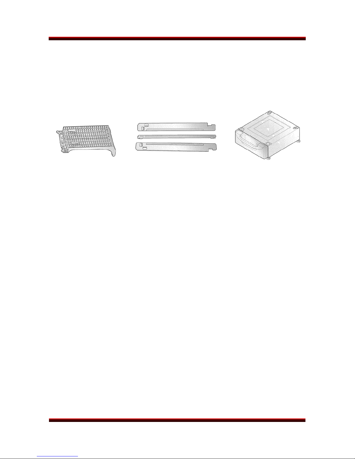
ACCESSORIES
The 9577/9588 dryer is shipped with a drying rack and a stacking kit. The
pedestal is optional. The dryer is designed to stack on the matching WM2496
washer. Both products can be stacked on a single pedestal, if desired, but the
dryer must always be on top of the washer.
DRYING RACK STACKING KIT PEDESTAL
INSTALLATION (RACK)
It’s simple!
Open the dryer door.
Set the rack in place.
Select RACK DRY.
(2nd button from top on the option row
on the right of the panel)
Press START.
Be sure the front of the rack is
properly situated in the notches on
either side of the filter. The back of the
rack should rest on the drum and
allow the drum to rotate.

DRYER 9577/9588
DLE9577/DLG9588 Page 11 of 58 TRAINING MANUAL
INSTALLATION (STACKING KIT)
Warning! Do not attempt this alone! At least two people are required to lift the
dryer and place it properly on top of the washer. Failure to observe this warning
could result in serious physical injury and damage to the appliances.
1. Place the washer on a solid,
even floor. If you plan to use a
pedestal, install it now, before
going any further.
(See page 12.)
2. Attach the side bracket loosely
to the top plate of the washer
but don’t tighten the screw all
the way.
3. Hold the bracket away from the
top plate and peel the protective
paper from the adhesive tape on
the side bracket. Hold the
adhesive surface off the top as
you tighten the screw. When the
screw is tight, attach the
adhesive tape to the top plate.
Repeat steps 2 and 3 for the
other side.
4. Level the legs on the dryer on a
flat floor before setting the dryer
on top of the washer.
5. Slide the dryer back into the
stops on the rails. Attach the
front bar with 2 screws to hold
the feet in place.

DRYER 9577/9588
DLE9577/DLG9588 Page 12 of 58 TRAINING MANUAL
INSTALLATION (PEDESTAL KIT)
This procedure covers installing and leveling the 7½” and 13” pedestals for 27”
washers, dryers, and combos. If the products are stacked, the washer must be
below the dryer, and you’ll use only one pedestal.
1. Remove the pedestal,
installation hardware, and
instructions form the shipping
carton. Set the pedestal as close
to the installation position as
possible.
2. Level the pedestal on a flat, solid
floor before proceeding. Lock
down the rear adjusters but
leave the front ones free for now.
3. Note which holes are for the
washer and which are for the
dryer. (See drawing, above.)
If you are stacking the
appliances, the washer must
be on the bottom.
4. Remove the protective paper
from the adhesive surface of the
bracket. Be particularly careful,
because when the adhesive
makes contact, there is no
adjustment possible.

DRYER 9577/9588
DLE9577/DLG9588 Page 13 of 58 TRAINING MANUAL
PEDESTAL, continued
5. Depending upon the model, your
pedestal may have straight or
curved brackets. The curved
ones are to be used on the rear
positions when mounting a dryer
to a pedestal, but can also be
used in any other position on the
pedestal.
6. Holding the exposed adhesive
away from the appliance, insert
the screws and get them started.
Then press the brackets to the
appliance and tighten all the
screws. Rub the bracket from
side to side to ensure a
complete bond.
7. Use the wrench to turn each leg
of the appliance approximately
¼ turn to put a little pressure
between the appliance and the
pedestal. This will eliminate any
rattles.
8. It is usually easier to set the
pedestal and washer into place
and connect the water and drain
hoses before placing the dryer
on top of them.

DRYER 9577/9588
DLE9577/DLG9588 Page 14 of 58 TRAINING MANUAL
ELECTRICAL CONNECTION (Electric Dryer Only)
PIGTAIL INSTALLATION
Install the appropriate power cord for the power outlet available. Grounding
through the neutral conductor is prohibited in new branch circuits, mobile homes,
recreational vehicles, and where prohibited by local code.
4-wire Connection
The 4-wire receptacle looks like this.
Your power cord may have spade or
ring connectors.
Install a strain relief on the power cord.
Then connect the terminals to the
terminal block, matching the wire
colors.
A. Ground screw on chassis
B. Green wire from power cord
C. Strain relief
D. Neutral screw on terminal block
E. Terminal block
F. Neutral wire from power cord

DRYER 9577/9588
DLE9577/DLG9588 Page 15 of 58 TRAINING MANUAL
3-wire Connection
The 3-wire receptacle looks like this.
Your power cord may have spade or
ring connectors.
Install a strain relief on the pigtail. Then
connect the terminals to the terminal
block, matching the wire colors. Add a
wire to connect the chassis ground to
neutral.
A. Ground screw on chassis
B. Green wire from pigtail
C. Strain relief
D. Neutral screw on terminal block
E. Ground-to-neutral connection
F. Neutral wire from pigtail

DRYER 9577/9588
DLE9577/DLG9588 Page 16 of 58 TRAINING MANUAL
ELECTRICAL CONNECTION (Electric Dryer Only) (Continued)
Be sure to tighten all screws firmly, but
do not strip them or distort the contact
area. Be sure to install a strain relief on
the power cord.
Replace the terminal block cover by
inserting the tabs into the slots and
letting them slide down to engage. Fold
it over to the back of the dryer so it
covers the access to the terminal block.
Be sure no wires are exposed or could
touch any metal surface.
Secure the cover with a screw.
ELECTRICAL CONNECTION (Gas Dryer Only)
The dryer requires a 120 VAC single-outlet dedicated circuit. The cord is installed
at the factory and no user-intervention is required.

DRYER 9577/9588
DLE9577/DLG9588 Page 17 of 58 TRAINING MANUAL
GAS CONNECTION (Gas Dryer Only)
CAUTION! (This warning applies to both natural gas and propane.)
Gas is both flammable and explosive. Use caution when working with gas. In
most locations, installing and connecting gas is restricted to properly trained,
certified, and licensed persons.
Always inspect joints and connections for a leak with a soapy solution. If you see
bubbles, turn the gas off and open a window. DO NOT use a match or flame.
If you smell gas, turn off the main valve and open a window.
1. Flex line (Bought in the length needed, with fittings attached to both ends)
2. Bleeding and pressure check port
3. Cut-off valve
4. Gas supply pipe
5. Point of attachment to dryer

DRYER 9577/9588
DLE9577/DLG9588 Page 18 of 58 TRAINING MANUAL
VENT PIPE CONNECTION
The dryer is shipped from the factory vented out the back. With the optional vent
kit (Part # 3911EZ9131X), the dryer can be vented out either side (left side only
for gas dryers because of gas piping interference) or the bottom (through the
floor). It is important to remember the vent must exhaust to outside air. The dryer
cannot be vented into a garage, an attic, or a crawl space beneath a house or
trailer. Follow these steps to change the vent output direction.
1. Remove the screw and the
existing exhaust vent pipe.
Install vent kit part number
3911EZ9131X.
2. Remove the appropriate
knockout (left, right, or bottom.)
The knockout is easily removed
by pressing one of the tabs
inside the dryer and popping it
out of the hole.
3. Insert the short duct piece with
the tab inside the dryer through
the hole on the back. Attach it
to the blower housing and align
the tab on the duct with the one
on the base. Install the screw.
4. Preassemble the elbow and the
remaining piece of duct. Seal
the joint with duct tape as
shown. (Be sure to use real,
heatproof duct tape rather than
an imitation.)
5. Connect the elbow to the duct
in the dryer and seal that joint
with duct tape.
Connect to the outside vent.

DRYER 9577/9588
DLE9577/DLG9588 Page 19 of 58 TRAINING MANUAL
REMOTE MONITOR and MODEM
The remote laundry monitor (RLM)
allows the user to monitor the
progress of both washer and dryer,
provided each is equipped with a
modem.
Remove the cover and install the
modem on the back of the dryer.
Save the small socket cover and
screws in the event you need to
remove the modem for some reason.
The socket should be covered at all
times.
For convenience, you can remove the
cover and install the modem on the
back of the washer.
Save the small socket cover and
screws in the event you need to
remove the modem for some reason.
The socket should be covered at all
times.
After installation is complete, plug in
the washer, dryer, and monitor, in that
order. Turn on the washer and dryer.
Press and hold the SET button on the
monitor.

DRYER 9577/9588
DLE9577/DLG9588 Page 20 of 58 TRAINING MANUAL
DRYER CYCLE CHART
On SENSOR DRY cycles, the dryness level is selected by the user.
On MANUAL DRY cycles, the drying time and temperature are set by the user.
On every cycle, the default settings can be overridden. Not all options will be
available, such as HIGH heat on the DELICATE cycle.
This manual suits for next models
1
Table of contents
Other LG Dryer manuals
Popular Dryer manuals by other brands

Schulthess
Schulthess WT14 EFH K installation instructions

juwel
juwel Comfort Plus 600 operating instructions

Electrolux
Electrolux EDE1070PDW user manual

Frigidaire
Frigidaire Affinity FAQG7077K W Specification sheet

Addvent
Addvent AVH15 Installation instructions and user guide

Siemens
Siemens WT47UHE9DN/I9DN Installation and operating instructions

Russell Hobbs
Russell Hobbs RH3VTD800 instruction manual

Whirlpool
Whirlpool CGM2751TQ - COMM GAS DRYR 3CYC 3TEMP 3LITE Brochure & specs

Lyman
Lyman Cyclone instruction manual

Indesit
Indesit IDCA G35 S instruction manual

Swiss
Swiss TYP operating instructions

Whirlpool
Whirlpool YWED9050XW installation instructions