LG DLEX8100V User manual

ELECTRIC & GAS DRYER
READ THIS MANUAL CAREFULLY TO DIAGNOSE
PROBLEMS PROPERLY AND TO PROVIDE
QUALITY SERVICE SAFELY ON THESE DRYERS.
U.S.A. Website: http://us.lgservice.com
Canadian Website: http://lg.ca
:
Electric Gas
DLEX8000*, DLGX8001*
DLEX8100*, DLGX8101*
Any reproduction, duplication, distribution (including by way of email, facsimile or other electronic means),
publication, modication, copying or transmission of this Service Manual is STRICTLY PROHIBITED unless you
have obtained the prior written consent of the LG Electronics entity from which you received this Service Manual.
The material covered by this prohibition includes, without limitation, any text, graphics or logos in this Service
Manual.
Copyright © 2016 - 2017 LG Electronics Inc. All rights reserved. Only training and service purposes.
CONFIDENTIAL

2
2
To avoid injury to persons, disconnect power before servicing this product. If electrical power is required
for diagnosis or test purposes, disconnect the power immediately after performing the necessary checks.
H
WARNING !
WHAT TO DO IF YOU SMELL GAS:
IMPORTANT SAFETY NOTICE
The information in this service guide is intended for use by individuals possessing skill and experience in
electrical, electronic, and mechanical appliance repair. Any attempt to repair a major appliance may result
in injury to persons, and property damage. The manufacturer or seller cannot be responsible for the
interpretation of this information, nor can it assume any liability in connection with its use.
RECONNECT ALL GROUNDING DEVICES
If grounding wires, screws, straps, clips, nuts, or washers used to complete a path to ground are
removed for service, they must be returned to their original position and properly fastened.
IMPORTANT
Electrostatic Discharge (ESD) Sensitive Electronics
ESD problems are present everywhere. ESD may damage or weaken the electronic
control assembly. The new control assembly may appear to work well after repair is
finished, but failure may occur at a later date due to ESD stress.
Use an anti-static wrist strap. Connect wrist strap to green ground connection point or unpainted
metal in the appliance.
- OR -
Touch your finger repeatedly to a green ground connection point or unpainted metal
in the appliance.
Before removing the part from its package, touch the anti-static bag to a green ground connection
point or unpainted metal in the appliance.
Avoid touching electronic parts or terminal contacts; handle electronic control assembly by edges only.
When repackaging the failed electronic control assembly in an anti-static bag, observe the instructions above.
Do not try to light a match, or cigarette, or turn on
any gas or electrical appliance.
Do not touch any electrical switches. Do not use
any phone in your building.
Clear the room, building, or area of all occupants.
Immediately call your gas supplier from a
neighbor’s phone. Follow the gas supplier’s
instructions carefully.
If you cannot reach your gas supplier, call the fire
department.

3
3
1. SPECIFICATIONS ............................................................................................................... 4
2. FEATURES AND BENEFITS ...............................................................................................6
3. INSTALLATION INSTRUCTIONS ........................................................................................6
4. DRYER CYCLE PROCESS ................................................................................................16
5. COMPONENT TESTING INFORMATION .........................................................................17
6. MOTOR DIAGRAM AND SCHEMATIC .............................................................................20
7. WIRING DIAGRAM ............................................................................................................21
8. STEAM FUNCTION ............................................................................................................22
8-1. Steam Cycle Guide ...................................................................................................22
8-2. Troubleshooting .........................................................................................................23
8-3. Display Fault/Error Codes ..........................................................................................24
9. FLOW SENSOR FUNCTION .............................................................................................25
9-1. Flow Sensor .............................................................................................................. 25
9-2. Installation Test (Exhaust Check) .............................................................................26
10. DIAGNOSTIC TEST ........................................................................................................28
10-1. TEST 1 120V AC Electrical Supply .......................................................................32
10-2. TEST 2 Thermistor Test - Measure With Power Off ..............................................33
10-3. TEST 3 Motor Test ................................................................................................34
10-4. TEST 4 Moisture Sensor ........................................................................................35
10-5. TEST 5 Door Switch Test ......................................................................................36
10-6. TEST 6 Heater Switch Test - Electric Type ...........................................................37
10-7. TEST 7 Gas Valve Test - Gas Type ......................................................................38
10-8. TEST 8 Motor Assembly, DC, Pump ....................................................................39
10-9. TEST 9 Generator Assembly ................................................................................39
11. CHANGE GAS SETTING (NATURAL GAS, PROPANE GAS) .......................................40
12. DISASSEMBLY INSTRUCTIONS ....................................................................................42
13. EXPLODED VIEW ............................................................................................................52
13-1. CONTROL PANEL AND PLATE ASSEMBLY .........................................................52
13-2. PANEL DRAWER ASSEMBLY and GUIDE ASSEMBLY .........................................53
13-3-1. CABINET and DOOR ASSEMBLY: ELECTRIC TYPE ........................................54
13-3-2. CABINET and DOOR ASSEMBLY: GAS TYPE ...................................................55
13-4-1. DRUM and MOTOR ASSEMBLY: ELECTRIC TYPE ..........................................56
13-4-2. DRUM and MOTOR ASSEMBLY: GAS TYPE .....................................................57
CONTENTS
Copyright © 2016 - 2017 LG Electronics Inc. All
rights reserved. Only training and service purposes.

4
1SPECIFICATIONS
See page 7
Stacking kit (1 each)
Purchased Separately
ACCESSORIES
Model DLEX8000*
DLEX8100*
DLGX8001*
DLGX8101*
Name Electric and Gas Dryer
Please refer to the rating label regarding detailed information
29” (W) X 32.1” (D) X 40.8” (H) (inch)
Size
Weight
Dryer capacity IEC 9.0 cu.Ft. IEC 9.0 cu.Ft.
158 (lbs) 161 (lbs)
Power supply
8egapeeS
Pedestal (1 each)
Purchased Separately
1SPECIFICATIONS

5
Sound levels
High / Medium / Low / Off
ITEM DLEX8000*
DLEX8100*
DLGX8000*
DLGX8101* REMARK
Blue White / Stainless Silver
Powder coating
Color
Top Plate
Door Trim
Power
Consumption
Motor
Heater
Lamp
Gas valve
AG heater
Pump
Control Type
Drum Capacity
Weight (lbs) - Net/Gross
Number of Programs
Number of Dry Options
Number of Temperature Controls
Moisture
Temperature
Number of Dry Levels
Reversible Door
Drum
Dryer Rack
Child Lock
Interior Light
Product (WxDxH)
Sensor
Power
Supply
Material and
Finish
Chrome
ELEC.
GAS
120 V / 240 V / 60 Hz (26 A)
120 V / 208 V / 60 Hz (23 A)
120 V / 60 Hz (13 A)
545 W (6.35 A)
5400 W (22.5 A)
4100 W (21 A)
1 W (0.085 A)
13 W (0.11 A) x 2
1100 W (9.2 A)
2.4 W (0.15 A)
Electronic
9.0 cu.ft.
158161
14
5
5
5
Available
Available
Available
Alcosta
Available
Available
Available
29" x 32.1" x 40.8"
Packing (WxDxH) 30.9" x 33.2" x 44.2"
AC 240 V (Electric Model)
AC 208 V (Electric Model)
DC 12V
DC 120V(Gas Model)
DC 120V(Steam Model)
DC 9V(Steam Model)
Thermistor
Electrode sensor

6
2FEATURES AND BENEFITS
DLEX8000* / DLGX8100*
DLEX8100* / DLGX8101*
6
Dryer Rack Installation Instructions
Open the door.
Hold the dryer rack
with both hands.
Put the dryer rack into
the drum
Check and be sure that the
front of the rack is properly
seated behind the lint filter.
2FEATURES AND BENEFITS
3INSTALLATION INSTRUCTIONS

7
Peel the protective paper from the tape on
the side bracket.
Secure the side bracket to the washer with
a screw on the back of the bracket. Repeat
Steps 2, 3, and 4 for the other side.
Place the dryer on top of the washer by
placing the legs as shown. Be careful not to
pinch fingers between the washer and dryer.
Slide the dryer back against the stop on the
side rail.
Fit the side bracket firmly to the side of the
top plate by attaching the double-faced tape
to the top plate as picture shown.
Insert the front rail of the stacking kit. Push
the front rail back against the stops on the
side brackets.
•Do not use a stacking kit with a gas dryer in
potentially unstable conditions like a mobile
home.
Stacking Kit Installation Instructions
Place the washer firmly on a stable, even
and solid floor as product installation
instructions describe in the owner’s
manual.
Do not attempt this alone!
At least twopeopleare requiredtoliftand
position the dryer on top of a washing
machine!
Failuretoheed this warning canresult in
serious physicalinjuryand damage to the
appliance.
To reduce the risk of Injury to persons adhere to all
industry recommended safety procedures including
the use of long sleeved gloves and safety glasses.
W A R N I N G
Stacking kit
Attach the front bracket to the side rails with
a screw on each side.
To ensure safe and secure installation, please observe the instructions below.

8
Pedestal Installation Instructions
•Drawer divider (1) •Wrench (1)
•Screws (18) † •T-clips (4) ††
•Phillips screwdriver
•Wrench (supplied)
† Dryer installation only uses 8 screws
†† For dryer only
To ensure safe and secure installation, please
thoroughly follow the instructions below.
•Incorrect installation can cause serious accidents.
•The appliances are heavy. Two or more people are
required when installing the pedestal. There is a
risk of serious back injury or other injuries.
•Do not allow children to play in or on the drawer.
There is a risk of suffocation or injury.
•Do not step on the handle. There is a risk of serious injury.
•If appliances are already installed, disconnect them
from all power, water, or gas lines and from draining or
venting connections. Failure to do so can result in
electrical shock, fire, explosion, or death.
•To reduce the risk of Injury to persons adhere to all industry
recommended safety procedures including the use of long
sleeved gloves and safety glasses.
WARNING
Retract fully
Retainer
T-clip
Make sure the leveling feet of the dryer are
fully retracted.
NOTE: The appliance and pedestal assembly
must be placed on a solid, sturdy, level floor
for proper operation.
Insert the T-clip of the 4 retainers into the dryer
base as shown. Press up on the back of the
clip and pull outward to lock into place.
Place the dryer on the
pedestal. Make sure
the front and back feet
are in the correct
positions. The dryer
feet will fit into the
innermost positions as
shown.
Make sure the screws on the pedestal align with the
holes in the retainers, then install 4 screws on each
side to securely attach the appliance to the pedestal.
NOTE: If the screws are not installed properly, noise
and vibration may result.
Move the appliance to the desired location.
Securely tighten all locknuts by hand.
NOTE: Noise and vibration may result if locknuts are not
tightened.
Be sure to connect the appliances to all water, power,
or gas lines and draining or venting connections before
operation.
If there is excessive vibration during the first operation
after installation, slightly adjust the leveling feet.
Loosen the locknuts on all 4 leveling feet of the
pedestal until you can turn them with the wrench.
Turn clockwise to raise or counterclockwise to lower
until the pedestal is level and all 4 feet are solidly
against the floor.
For dryer
For washer/combo
Raise Lower
Locknut

9
11
WARNING
To reduce the risk of fire, electric shock, or injury to persons when using this appliance, follow basic precautions, including the following:
Electrical Requirements for Gas Models Only
WARNING
To reduce the risk of fire, electric shock, or Injury to persons when using this appliance, follow basic precautions, including the following:
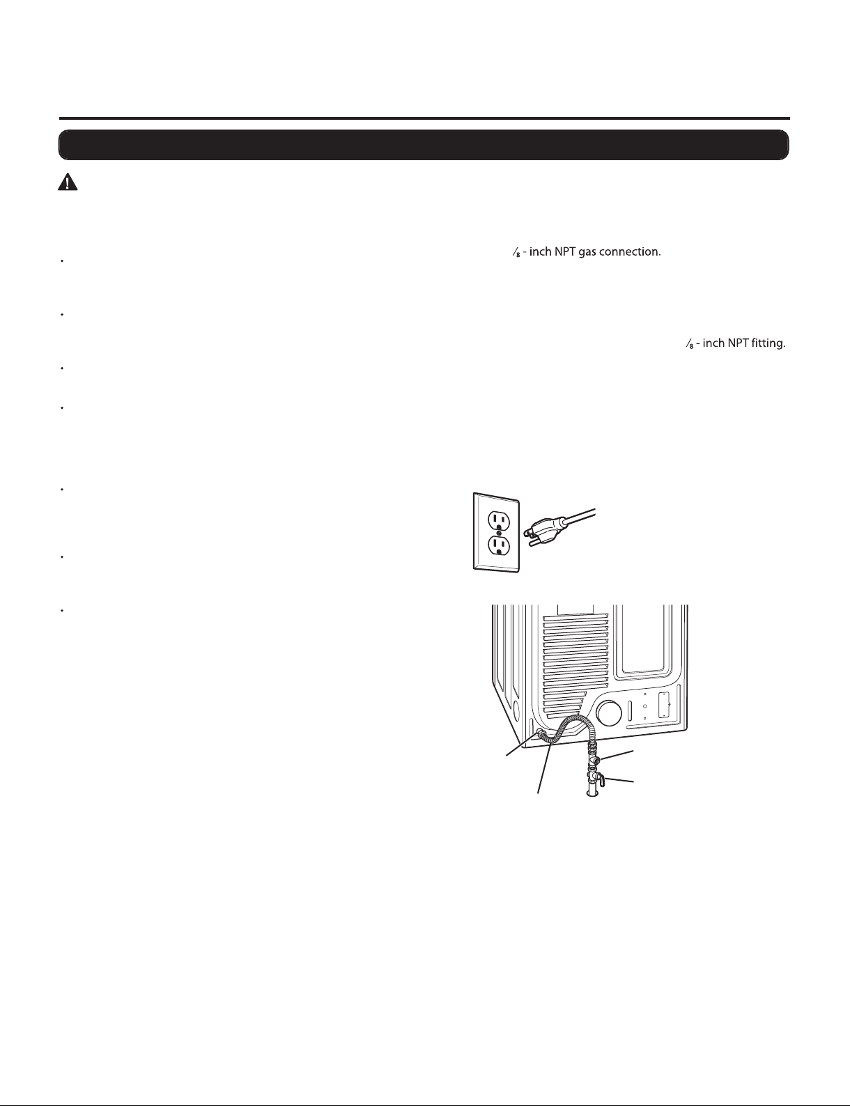
Do not, under any circumstances, cut or remove the third
(ground) prong from the power cord. Failure to follow this
warning can result in fire, explosion, or death.
For personal safety, this dryer must be properly grounded.
Failure to follow this warning can result in fire, explosion, or death.
The power cord of this dryer is equipped with a 3-prong
(grounding) plug which mates with a standard 3-prong
(grounding) wall outlet to minimize the possibility of electric
shock hazard from this appliance. Failure to follow this warning
can result in fire, explosion, or death.
This dryer must be plugged into a 60 Hz, 120 VAC, grounded
outlet protected by a 15-ampere fuse or circuit breaker. Failure
to follow this warning can result in fire, explosion, or death.
Where a standard 2-prong wall outlet is encountered,it is your
personal responsibility and obligation to have it replacedwith
a properly grounded 3-prong wall outlet. Failure to follow this
warning can result in fire, explosion, or death.
Gas supply requirements:
As shipped from the factory, this dryer is configured for use
with naturalgas.It canbeconverted for usewith LP (Liquefied
Propane) gas. Gas pressure must not exceed 13 inches of
water column.
A qualified service or gas company technician must connect
the dryer to the gas service.
Failure to do so can result in fire, explosion, or death.
Isolate the dryer from the gas supply system by closing its
individual manual shutoff valve during any pressure testing
of the gas supply.
Failure to do so can result in fire, explosion, or
death.
Supply line requirements:
Your laundry room must have a rigid gas supply line to your
dryer. In the United States, an individual manual shutoff valve
MUST be installed within at least 6 ft. (1.8 m) of the dryer, in
accordance with the National Fuel Gas Code ANSI Z223.1 or
Canadian gas installation code CSA B149.1. A
18
pipe plug must be installed. Failure to do so can result in fire,
explosion, or death
If using a rigid pipe, the rigid pipe should be ½ - inch IPS.
If acceptable under local codes and ordinances and when
acceptable to your gas supplier, 38roved tubing
may be used where lengths are less than 20 ft. (6.1 m). Larger
tubing should be used for lengths in excess of 20 ft. (6.1 m).
Failure to do so can result in fire, explosion, or death.
Connect the dryer to the type of gas shown on the nameplate.
Failure to do so can result in fire, explosion, or death.
To prevent contamination of the gas valve, purge the gas
supply of air and sediment before connecting the gas supply
to the dryer. Before tightening the connection between the
gas supply and the dryer, purge remaining air until the odor
of gas is detected.Failure to do so can result in fire, explosion, or
death.
DO NOT use an open flame to inspect for gas leaks. Use a
noncorrosive leak-detection fluid. Failure to do so can result in
fire, explosion, or death.
Use only a new AGA- or CSA-certified gas supply line with
flexible stainless steel connectors. Failure to do so can result in
fire, explosion, or death.
Securely tighten all gas connections. Failure to do so can result
in fire, explosion, or death.
DO NOT attempt any disassembly of the dryer; any
disassembly requires the attention and tools of an authorized
and qualified service person or company. Failure to do so can
result in fire, explosion, or death.
Use a pipe-joint compound that is insoluble in Liquefied
Petroleum (LP) gas on all pipe threads. Failure to do so can
result in fire, explosion, or death.
Connecting gas dryers

10
12
WARNING
To reduce the risk of fire, electric shock, or injury to persons when
using this appliance, follow basic precautions, including the
following:
Installation and service must be performed by a qualified
installer, service agency, or the gas supplier. Failure to do so
can result in fire, explosion, or death.
Use only a new stainless steel flexible connector and a new
AGA-certified connector. Failure to do so can result in fire,
explosion, or death.
A gas shutoff valve must be installed within 6 ft. (1.8 m) of
the dryer. Failure to do so can result in fire, explosion, or death.
The dryer is configured for Natural Gas when shipped from
the factory. Make sure that the dryer is equipped with the
correct burner orifice for the type of gas being used (Natural
Gas or Liquefied Petroleum). Failure to do so can result in fire,
explosion, or death.
If necessary, the correct orifice (for the LP, orifice kit order
part number 383EEL3002D) should be installed by a
qualified technician and the change should be noted on the
dryer. Failure to do so can result in fire, explosion, or death.
All connections must be in accordance with local codes and
regulations . Failure to do so can result in fire, explosion, or
death.
Gas dryers MUST exhaust to the outdoors.Failure to do so can
result in fire, explosion, or death.
Connecting the Gas Supply
1.Make sure that the gas supply to the laundry room is turned
OFF. Confirm that thetypeof gas available in your laundry room
is appropriate for the dryer. The dryer is prepared for Natural
Gas with a
3
2.Remove the shipping cap from the gas connection at the back
of the dryer. Be careful not to damage the threads of the gas
connector when removing the shipping cap.
3.Connect the dryer to your laundry room’s gas supply using a
new flexible stainless steel connector with a
3
4.Securely tighten all connections between the dryer and your
laundry room’s gas supply. Turn on your laundry room’s gas
supply and check all pipe connections (both internal and
external) for gas leaks with a noncorrosive leak-detection fluid.
Electrical Connection
High-Altitude Installations
The BTU rating of this dryer is AGA-certified for elevations below
10,000 feet.
If your gas dryer is being installed at an elevation above 10,000
feet, it must be derated by a qualified technician or gas supplier.
Plug dryer into a 120 VAC, 60
Hz grounded 3-prong outlet.
3/8” NPT Gas
Connection Gas Supply
Shutoff Valve
1/8” NPT Pipe
Plug
AGA/CSA-Certified
Stainless Steel Flexible
Connector
Connecting gas dryers(cont.)

11
Connecting electric dryers

12
14
WARNING
Connect the power cord to the terminal block. Each colored
wire should be connected to same color screw. Wire color
indicated on manual is connected to the same color screw
in block. Failure to follow these instructions may result in a
short or overload.
Grounding through the neutral conductor is prohibited
for: (1) new branch-circuit installations, (2) mobile homes,
(3) recreational vehicles, and (4) areas where local codes
prohibit grounding through the neutral conductor.
Four-Wire Connection for Electric Dryers:
Power Cord
A 4-wire connection is required for all mobile and manufactured
home installations,as well as all new construction after January 1,
1996.
• A UL-listed strain relief is required.
Remove the terminal block access cover on the upper back of
the dryer. Install a UL-listed strain relief into the power cord
through-hole; then thread a UL-listed, 30 A, 240 V, 4-wire, #10
AWG-minimum copper conductor power cord through the
strain relief.
Use a 30 A, 240 V, UL-listed power cord with #10 AWG-
minimum copper conductor and closed loop or forked
terminals with upturned ends.
Transfer the dryer’s ground wire from behind the green ground
screw to the center screw of the terminal block. Attach the two
hot leads of the power cord to the outer terminal block screws.
Attach the white neutral wire to the center terminal block
screw. Attach the power cord ground wire to the green ground
screw.TIGHTENALL SCREWS SECURELY. Reinstall the terminal
block access cover.
UL-Listed
Strain Relief
UL-Listed
4-Wire Power
Cord
Terminal
Block
Ground
Screw
Neutral
(White)
Hot
(Black)
Ground Wire
Hot
(Red)
Connecting electric dryers(cont.) USA only

13
15
WARNING
Connect the power cord to the terminal block. Each colored
wire should be connected to same color screw. Wire color
indicated on manual is connected to the same color screw
in block. Failure to follow these instructions may result in a
short or overload.
Grounding through the neutral conductor is prohibited
for: (1) new branch-circuit installations, (2) mobile homes,
(3) recreational vehicles, and (4) areas where local codes
prohibit grounding through the neutral conductor.
Four-WireConnection for Electric Dryers:Direct Wire
A 4-wire connection is required for all mobile and manufactured
home installations,as well as all new construction after January 1,
1996.
• A UL-listed strain relief is required.
Remove 5 inches (12.7 cm) of the outer covering from the wire.
Remove 5 inches of insulation from the ground wire. Cut off
approximately 112rom the other three wires
and strip 1 inch (2.5 cm) insulation from each wire. Bend the
ends of the three shorter wires into a hook shape.
Remove the terminal block access cover on the upper back of
the dryer. Install a UL-listed strain relief into the power cord
through-hole; then thread the power cable prepared in Step 1
through the strain relief.
Use UL-listed 4-wire #10 AWG-minimum copper conductor
cable.
Allow at least 5 ft. (1.5 m) length to allow for removal and
reinstallation of the dryer.
Transfer the dryer’s ground wire from behind the green ground
screw to the center screw of the terminal block. Attach the two
hot leads of the power cable to the outer terminal block screws.
Attach the white neutral wire to the center terminal block
screw. Attach the power cable ground wire to the green ground
screw. TIGHTEN ALLSCREWS SECURELY. Reinstall the terminal
block access cover.
Ground Wire
5"
(12.7 cm)
1" (2.5 cm)
UL-Listed
Strain Relief
UL-Listed
4-Wire Power
Cord
Terminal
Block
Ground
Screw
Neutral
(White)
Hot
(Black)
Ground Wire
Hot
(Red)
Connecting electric dryers(cont.) USA only

14
16
WARNING
Connect the power cord to the terminal block. Each colored
wire should be connected to same color screw. Wire color
indicated on manual is connected to the same color screw
in block. Failure to follow these instructions may result in a
short or overload.
Grounding through the neutral conductor is prohibited
for: (1) new branch-circuit installations, (2) mobile homes,
(3) recreational vehicles, and (4) areas where local codes
prohibit grounding through the neutral conductor.
Three-Wire Connection for Electric Dryers:
Power Cord
A 3-wire connection is NOT permitted on new construction after
January 1, 1996.
• A UL-listed strain relief is required.
Remove the terminal block access cover on the upper back of
the dryer. Install a UL-listed strain relief into the power cord
through-hole; then thread a UL-listed, 30 A, 240 V, 3-wire, #10
AWG-minimum copper conductor power cord through the
strain relief.
Use a 30 A, 240 V, UL-listed power cord with #10 AWG-
minimum copper conductor and closed loop or forked
terminals with upturned ends.
Attach the two hot leads of the power cord to the outer
terminal block screws. Attach the neutral wire to the center
terminal block screw. Connect the external ground (if required
by local codes) to the green ground screw.TIGHTEN ALL
SCREWS SECURELY. Reinstall the terminal block access cover.
UL-Listed
Strain Relief
UL-Listed
3-Wire Power
Cord
Terminal
Block
Ground
Screw
Neutral
(White)
Hot
(Black)
Power Cord
Ground Wire
Hot
(Red)
Connecting Electric Dryers(cont.) USA only

15
Connecting Electric Dryers(cont.) USA only

16
4DRYER CYCLE PROCESS
Cycle
Default
Conditions of operation and termination
Temp-
erature
Dry
Level
Display
time
Drying Cooling
Wrinkle care
Time
Electro-
sensor
Temp-
Control
Default
time
Temp-
Control**
Load
Motor
Heater
Temperature Control foreach cycl e
Off Time: 6 mi n
On Time: 10 sec
*Sensor dry : Dry Level is set by users.
**Manual dry : Temperature control is set by users.
Default settings can be adjusted by users.
DLEX8000* / DLGX8001*
DLEX8100* / DLGX8101*
Sensor
Dry
STEAM FRESH
TM
ANTI
BACTERIAL
PERM PRESS
COTTON/NORMAL
DELICATES
TOWELS
WOOL
JUMBO DRY
HEAVY DUTY
SPOT CLEAN
SUPER DRY
STEAM
SAINTARY
TM
TM
MID HIGH
MID HIGH
MEDIUM
MEDIUM
MEDIUM
Very DRY
HIGH
HIGH
HIGH
HIGH
LOW
LOW
LOW
20 min
Saturation
Saturation
Saturation
Saturation
Saturation
Saturation
Saturation
Saturation
Saturation
Saturation
64±2˚C 45±5˚C
45±5˚C
45±5˚C
45±5˚C
45±5˚C
45±5˚C
45±5˚C
45±5˚C
45±5˚C
45±5˚C
45±5˚C
38±5˚C
66±2˚C
66±2˚C
66±2˚C
66±2˚C
60±2˚C
58±2˚C
50±2˚C
66±2˚C
66±2˚C
5 min
5 min
5 min
5 min
5 min
5 min
5 min
5 min
5 min
5 min
39 min
70 min
Saturation
5 min
54 min
85 min
32 min
41 min
28 min
55 min
55 min
59 min
3 Hr
Saturation
5 min
22 min
Manual
Dry
SPEED DRY HIGH
NO HEAT
Saturation
5 min
25 min
3 Hr
66±2˚C
ADJUSTABLE
ADJUSTABLE
NORMAL
ADJUSTABLE
NORMAL
ADJUSTABLE
NORMAL
ADJUSTABLE
NORMAL
ADJUSTABLE
NORMAL
ADJUSTABLE
OFF
OFF
OFF
VERY
OFF
OFF
AIR DRY
Saturation
30 min
OFF
50±2˚C
60±2˚C
NORMAL
ADJUSTABLE
When checking components, turn the power off and discharge voltage.
COMPONENT TESTING INFORMATION
5
!
CAUTION
Component Test Procedure Check result Remark
1. Thermal cut off
•Check Top Marking:
N140
Measure resistance of terminal
to terminal
Open at 284 ±41°F
(140 ±5°C)
Auto reset -31°F (-35°C)
Same shape as outlet thermostat.
If thermal fuse is open must
be replaced
Resistance value ∞
Continuity (250°F ˨) <1Ω
•Heater case-
Safety
•Electric type
2. Hi limit Thermostat
(Auto reset)
Measure resistance of terminal
to terminal
Open at 257 ±9°F
(125 ±5°C)
Close at 221 ±9°F
(94 ±7°C)
Resistance value ∞
Resistance value <5Ω
•Heater case -
Hi limit
•Electric type
3. Outlet Thermostat
( Auto reset)
•Check Top Marking:
N85
Measure resistance of terminal
to terminal
Open at 185 ±41°F
(85 ±5°C)
Close at 167 ±41°F
(75 ±5°C)
Same shape as thermal cut off.
Resistance value ∞
Resistance value <5Ω
•Blow housing -
Safety
•Electric type
4. LED Lamp Schematic: If the lamp is turned on
by connecting is normal.
It is not
measured by
multimeter
because V is
3.2V
th
6. Idler switch Measure resistance of the
following terminal:
COM - NC
1. Lever open
Resistance value <1Ω
2. Lever push (close)
Resistance value ∞
5. Door switch Measure resistance of the
following terminal
1) Door open
Terminal: COM - NC (1-3)
Terminal: COM - NO (1-2)
2) Door closed
Terminal: COM - NC (1-3)
Terminal: COM - NO (1-2)
Resistance value <1Ω
Resistance value ∞
Resistance value ∞
Resistance value <1Ω
19
4DRYER CYCLE PROCESS

17
When checking components, turn the power off and discharge voltage.
COMPONENT TESTING INFORMATION
5
!
CAUTION
Component Test Procedure Check result Remark
1. Thermal cut off
•Check Top Marking:
N140
Measure resistance of terminal
to terminal
Open at 284 ±41°F
(140 ±5°C)
Auto reset -31°F (-35°C)
Same shape as outlet thermostat.
If thermal fuse is open must
be replaced
Resistance value ∞
Continuity (250°F ˨) <1Ω
•Heater case-
Safety
•Electric type
2. Hi limit Thermostat
(Auto reset)
Measure resistance of terminal
to terminal
Open at 257 ±9°F
(125 ±5°C)
Close at 221 ±9°F
(94 ±7°C)
Resistance value ∞
Resistance value <5Ω
•Heater case -
Hi limit
•Electric type
3. Outlet Thermostat
( Auto reset)
•Check Top Marking:
N85
Measure resistance of terminal
to terminal
Open at 185 ±41°F
(85 ±5°C)
Close at 167 ±41°F
(75 ±5°C)
Same shape as thermal cut off.
Resistance value ∞
Resistance value <5Ω
•Blow housing -
Safety
•Electric type
4. LED Lamp Schematic: If the lamp is turned on
by connecting is normal.
It is not
measured by
multimeter
because V is
3.2V
th
6. Idler switch Measure resistance of the
following terminal:
COM - NC
1. Lever open
Resistance value <1Ω
2. Lever push (close)
Resistance value ∞
5. Door switch Measure resistance of the
following terminal
1) Door open
Terminal: COM - NC (1-3)
Terminal: COM - NO (1-2)
2) Door closed
Terminal: COM - NC (1-3)
Terminal: COM - NO (1-2)
Resistance value <1Ω
Resistance value ∞
Resistance value ∞
Resistance value <1Ω
19
5COMPONENT TESTING INFORMATION

18
Component Test Procedure Check result Remark
7. Heater Measure resistance of the
following terminal
Terminal: 1 (COM) - 2
Terminal: 1 (COM) - 3
Terminal: 2 - 3
Resistance value: 10Ω
Resistance value: 20Ω
•Electric type
8. Thermistor Measure resistance of terminal
to terminal
Temperature condition:
58°F ~ 104F (10~40°C)
Resistance value: 10Ω•Heater case -
Hi limit
•Electric type
9. Motor •See Page 21
10. Gas valve valve 1
valve 2
Measure resistance of the
following terminal
Valve 1 terminal
Valve 2 terminal
Resistance value: >
1.5~2.5 kΩ
•Gas type
11. Igniter Measure resistance of terminal
to terminal
Resistance value: 50~800 Ω•Gas type
12. Flame Detect Measure resistance of terminal
to terminal
Open at 370°F ((Maximum)
Close at 320°F
Resistance value ∞
Resistance value <1Ω
•Gas type
20

19
Component Test ProcedureCheck resu lt Remark
13. Outlet Thermostat
(Auto reset)
•Check Top Marking:
N95
Measure resistance of terminal
to terminal
Open at 203 ±41°F (95 ±5°C)
Close at 158 ±41°F (70±5°C)
Resistance value ∞
Continuity <1Ω
•Gas type
•Gas funnel
14. Outlet Thermostat
(Manual reset)
•Check Top Marking:
N110
Measure resistance of terminal
to terminal
Open at 230 ±41°F
(110 ±5°C)
Manual reset
Resistance value ∞
Continuity <1Ω
•Gas type
•Gas funnel
21

20
MOTOR DIAGRAM AND SCHEMATIC
6
Contact On / Off by Centrifugal Switch
STOP MODE
(When Motor does not operate)
RUN MODE
(Motor operates)
When checking components, turn the power off and discharge voltage.
NOTE
Centrifugal switch Centrifugal switch
(Pull Drive forward)
22
7WIRING DIAGRAM
23
6MOTOR DIAGRAM AND SCHEMATIC
This manual suits for next models
4
Table of contents
Other LG Dryer manuals