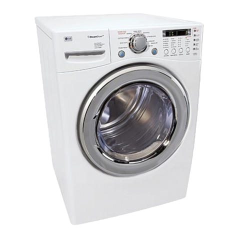
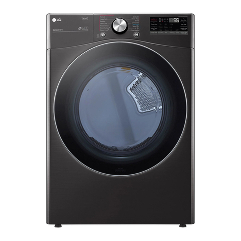
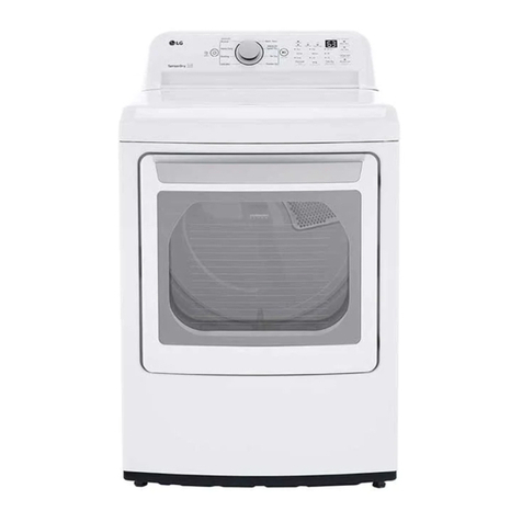
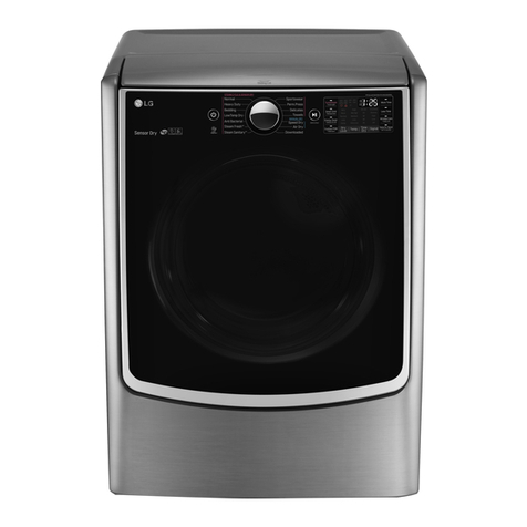
LG DLEY1701 User manual

ELECTRIC & GAS DRYER
SERVICE MANUAL
CAUTION
READ THIS MANUAL CAREFULLY IN ORDER TO
PROPERLY DIAGNOSE PROBLEMS AND TO SAFELY
PROVIDE QUALITY SERVICE ON THESE DRYERS.
U.S.A Website: http://us.lgservice.com
Canadian Website: http://lg.ca
DLEY1701*E, DLGY1702*E
Any reproduction, duplication, distribution (including by way of email, facsimile or other electronic means), publication,
modication, copying or transmission of this Service Manual is STRICTLY PROHIBITED unless you have obtained the
prior written consent of the LG Electronics entity from which you received this Service Manual. The material covered by
this prohibition includes, without limitation, any text, graphics or logos in this Service Manual.
Copyright © 2016 - 2017 LG Electronics Inc. All rights reserved. Only training and service purposes.

2
To avoid personal inju ry, disconnect power before se rvicing this product. If electrical power is required
for diagnosis or test purposes, disconnect the power immediately after pe rforming the necessary checks.
To reduce the risk of personal injury, adhere to all industry recommended safety procedures including the
use of long sleeved gloves and safety glasses. Failure to follow all of the safety warnings in this manual
could result in property damage, personal injury or death.
!
WARNING !
WHAT DO IF YOU SMELL GAS :
IMPORTANT SAFETY NOTICE
The information in this service guide is intended for use by individuals possessing skill and experience in
electrical, electronic, and mechanical appliance repair. Any attempt to repair a major appliance may result
in personal injury and property damage. The manufacturer or seller cannot be responsible for the
interpretation of this information, nor can it assume any liability in connection with its use.
RECONNECT ALL GROUNDING DEVICES
If grounding wires, screws, straps, clips, nuts, or washers used to complete a path to ground are
removed for service, they must be returned to their original position and properly fastened.
IMPORTANT
Electrostatic Discharge (ESD)
Sensitive Electronics
ESD problems are present everywhere. ESD may damage or weaken the electronic control
assembly. The new control assembly may appear to work well after repair is finished,
but failure may occur at a later due to ESD stress.
Touch your finger repeatedly to a green ground connection point or unpainted metal in the
appliance.
Use an anti-static wrist strap. Connect wrist strap to green ground connection point or unpainted
metal in the appliance. - OR -
Before removing the part from its package, touch the anti-static bag to a green ground connection
point or unpainted metal in the appliance.
Avoid touching electronic parts or terminal contacts; handle electronic control assembly by edges only.
When repackaging failed electronic control assembly in anti-static bag, observe above instructions.
Do not try to light a match, or cigarette, or turn on
any gas or electrical appliance.
Do not touch any electrical switches. Do not use
any phone in your building.
Clear the room, building or area of all occupants.
Immediately call your gas supplier from a
neighbor’s phone. Follow the gas supplier’s
instructions carefully.
If you cannot reach your gas supplier, call the fire
department.

3
CONTENTS
1. SPECIFICATIONS.................................................................................................................. 4
2. FEATURES AND BENEFITS ................................................................................................. 6
3. INSTALLATION INSTRUCTIONS.......................................................................................... 6
4. DRYER CYCLE PROCESS ................................................................................................. 10
5. COMPONENT TESTING INFORMATION ........................................................................... 11
6. MOTOR DIAGRAM AND SCHEMATIC................................................................................ 14
7. WIRING DIAGRAM .............................................................................................................. 15
8. FLOW SENSOR FUNCTION ............................................................................................... 16
8-1. FLOW SENSOR........................................................................................................... 16
8-2. INSTALLATION TEST................................................................................................... 17
8-3. TROUBLESHOOTING FOR FLOW SENSOR DRYER ................................................ 19
9. DIAGNOSTIC TEST............................................................................................................. 20
9-1. TEST 1 120V AC ELECTRICAL SUPPLY .................................................................... 21
9-2. TEST 2 THERMISTOR TEST - MEASURE WITH POWER OFF ................................. 22
9-3. TEST 3 MOTOR TEST.................................................................................................. 23
9-4. TEST 4 MOISTURE SENSOR...................................................................................... 24
9-5. TEST 5 DOOR SWITCH TEST..................................................................................... 25
9-6. TEST 6 HEATER SWITCH TEST - ELECTRIC TYPE.................................................. 26
9-7. TEST 7 GAS VALVE TEST - GAS TYPE...................................................................... 27
10. CHANGE GAS SETTING (NATURAL GAS, PROPANE GAS).......................................... 28
11. DISASSEMBLY INSTRUCTIONS .................................................................................... 30
12. DOOR REVERSE............................................................................................................... 42
13. SCREW POSITION............................................................................................................ 48
14. Tag On................................................................................................................................ 50
15. EXPLODED VIEW.............................................................................................................. 57
15-1-1. CONTROL PANEL AND PLATE ASSEMBLY: ELECTRIC TYPE ......................... 57
15-1-2. CONTROL PANEL AND PLATE ASSEMBLY: GAS TYPE ................................... 58
15-2-1. CABINET & DOOR ASSEMBLY:ELECTRIC TYPE............................................... 59
15-2-2. CABINET & DOOR ASSEMBLY:GAS TYPE......................................................... 60
15-3-1. DRUM AND MOTOR ASSEMBLY: ELECTRIC TYPE.......................................... 61
15-3-2. DRUM AND MOTOR ASSEMBLY: GAS TYPE..................................................... 62
Copyright © 2016 - 2017 LG Electronics Inc. All
rights reserved. Only training and service purposes.

1SPECIFICATIONS
4
Name: Electric and Gas Dryer
Power supply: Refer to the rating label on the dryer.
Gas: 120 VAC Electric: 240VAC
Specifications are subject to change by manufacturer.
Size: 27”X 403/16
”X 29”(inch)
Dryer capacity: IEC 7.3 cu.ft.
Weight: Gas 137.9 Ibs (62.54kg)
Electric 135.1lbs (61.28kg)
See page 6 of this manual for usage instruction.
Dryer rack (1 each)
ACCESSORIES
Yconnector Hose
Included accessories

5
Sound levels
3(High/Low/off)
ITEM DLEY1701*E DLGY1702*E REMARK
Blue White / Stainless Silver
Silver / Black
Color
ELEC.
GAS
Top Plate
Door Trim
ELECTRICITY
CONSUMPTION
MOTOR
HEATER
LAMP
GAS VALVE
CONTROL TYPE
DRUM CAPACITY
Weight (lbs) - Net
No. of Programs
No. of Dry Options
No. of Temperature Controls
Moisture
Temperature
No. of Dry Levels
Reversible Door
Drum
Child Lock
Interior Light
Product (WxHxD)
Packing (WxHxD)
Sensor
POWER
SUPPLY
Material &
Finish
Chrome
120/240V 60Hz (26A)/120/208V 60Hz (23A)
120V/60Hz (11.5A)
250W (4.5A)
5400W (22.5A)
4100W (21A)
15 W (0.2A)
13 W (0.11A) x 2
Electronic
7.3 cu.ft.
Gas 137.9Ibs (62.54kg), Electric 135.1lbs (61.28kg)
12
7
5
5
Available
Available
Available
Stainless Steel
Available
Available
27
”
x
403/16
”
x 29
”
(inch)
29
”
x
403”
x 30
”
(inch)
AC 120V
AC 240V(ELECTRIC MODEL)
AC 208V(ELECTRIC MODEL)
AC 120V
DC 12V
AC 120V(GAS MODEL)
INLET VALVE 14
Thermistor
Electrode sensor

2FEATURES AND BENEFITS
6
3INSTALLATION INSTRUCTIONS
Open the door.
Hold the dryer rack
with both hands.
Put the dryer rack into
the drum Check and be sure that the
front of the rack is properly
seated on the lint filter.

7
Use the instructions under option 2 or 3 if your
home has a 3-wire receptacle (NEMA type 10-30R)
Use option 2 if local codes and ordinances permit
the connection of a chassis ground to the neutral
connector If this is not permitted, use option 3
3-1. Connecting Electric Dryers
If this type is available at your home you will be
connecting to a fused disconnect or circuit breaker
box
Grounding through the neutral conductor
is prohibited for (1) new branch-circuit installations,
(2) mobile homes, and (3) recreational vehicles, and
(4) areas where local codes prohibit grounding through
the neutral conductor
Prepare minimum 5 ft (1 52 m) of length in order for
dryer to be replaced
First, peel 5 inches (12 7 cm) of covering material from
end Make a 5 inches of ground wire bared After cutting
1
1
/2inches (3 8 cm) from 3 other wires peel insulation
back 1inch (2 5 cm) Make ends of 3 wires a hook
shape
Then, put the hooked shape end of the wire under the
screw of the terminal block(hooked end facing rightward)
and pinch the hook together and screw tightly
Use the instructions under option 1 if your home
has a 4-wire receptacle (NEMA type 14-30R)
If this type is available at your home you will be
connecting to a fused disconnect or circuit breaker
box
1 Connect neutral wire(white) of power cord to center
terminal block screw
2 Connect red and black wire to the left and right
terminal block screws
3 Connect ground wire(green) of power cord to external
ground screw and move neutral ground wire of
appliance and connect it to center screw
4 Make sure that the strain relief screw is tightened
and be sure that all terminal block nuts are on tight and
power cord is in right position
1"
(2.5 cm)
5"
(12.7 cm)
!"
!!"
5"
(12.7 cm)
#
1"
(2.5 cm)
5"
(12.7 cm)
F
ab
E
D
C


4DRYER CYCLE PROCESS
10
STEAM
FRESHTM
BULKY/
BEDDING
CASUAL
EXPRESS DRY
HIGH
HIGH Off 18min
Off 14min
Elec:67
Gas:73
28min
32min
WRINKLE
FREE
68±4℃
155±7℉
66±4℃
151±7℉
The Energy Saver option is turned on by default in the Cotton/Normal cycle.
Turn off the Energy Saver option for a faster Normal cycle which begins with heated drying.
To turn the Energy Saver default off, press and hold the Wrinkle Care button for three seconds.
ON or OFF appears in the display.
Note
* Sensor dry: Dry Level is set by users.
** Manual dry: Temperature control is set by users.
Default settings can be adjusted by users.

5COMPONENT TESTING INFORMATION
11
1. Thermal cut off Measure resistance of terminal
to terminal
Open at 284 9
℉
(140 5
℃
)
Same shape as Outlet Thermostat.
If thermal fuse is open must
be replace
esistance value
Continuity (250
℉
)<1
Ω
·
Heater case-
Safety
·
Electric type
·
Heater case -
Hi limit
·
Electric type
·
Blow housing -
Safety
Measure resistance of terminal
to terminal
Open at 257 9
℉
(125 5°C)
Close at 201 12
℉
(94 7°C)
Measure resistance of terminal
to terminal
Open at 185 9
℉
(85 5
℃
)
Same shape as Thermal cut off.
Measure resistance of terminal
to terminal
esistance value
esistance value < 5
Ω
esistance value
esistance value < 5
Ω
esistance value < 1
Ω
esistance value
esistance value
esistance value < 1
Ω
esistance value:
80
Ω
~
100
Ω
1. lever open
esistance value < 1
Ω
2. Lever push (close)
esistance value
·
CheckTop Marking:
N140
2.Hi limit Thermostat
(Auto reset)
3.Outlet Thermostat
(Cut off)
·
CheckTop Marking:
N85
4. Lamp holder
5. Door switch Measure resistance of the
following terminal
1) Door switch knob: open
Terminal: COM - NC(1-3)
Terminal: COM-NC(1-2)
2) Door switch push: push
Terminal: COM - NC (1-3)
Terminal: COM - NC (1-2)
6. Idler switch Measure resistance of the
following terminal:
COM-NC
!
CAUTION
When checking the Component, be sure to turn the power off, and do voltage discharge sufficiently.
Component Test Procedure
Check result
Remark

12
7. Heater Measure resistance of the
following terminal
Terminal: 1 (COM) - 2
Terminal: 1 (COM) - 3
Terminal:2-3
11. Igniter Measure resistance from
terminal to terminal.
318EL3001
Measure resistance of the
following terminal
Valve 1 terminal
Valve 2 terminal
8. Thermistor Measure resistance of terminal
to terminal
Temperature condition:
9. Motor
10. Gas valve
Resistance value: 20
Resistance value: 40
Resistance value: 10
valve 1
valve 2
Component Test Procedure
Check result
Remark
Resistance value :1. ~2.
14
Resistance value : 100~800
12. Frame Detect Measure resistance of termina
to terminal Resistance value

13
13. Outlet Thermostat
(Auto reset)
14. Outlet Thermostatt
(Manual reset)
Measure resistance of terminal
to terminal
Open at 203 7F(95 5C
Close at 159 9F(70 5C)
Gas type
Gas funnel
Gas type
Electric type
Gas funnel
Measure resistance of terminal
to terminal
Open at 212 12 F
(110 7C)
Manual reset
If thermal fuse is open must
be replaced
Resistance value
Continuity < 1
Ω
·Check Top Marking:
N95
·Check Top Marking:
N110
Resistance value
Continuity < 1
Ω
Component Test Procedure
Check result
Remark
15. Inlet. valve Measure resistance of the
Following terminal
Left picture
-.plate

6MOTOR DIAGRAM AND SCHEMATIC
14
RUN MODE
(Motor operates)
STOP MODE
(When Motor does not operate)
Centrifugal switch Centrifugal switch
(Pull Drive forward)
NOTE
When checking components, be sure turn the power off, then do voltage discharge sufficiently.
Contact On / Off by Centrifugal Switch
Terminal No
Mode Resistance
Motor
STOP
Motor
RUN
2 ~ 3Ω
≒∞
≒∞
3 ~ 5
Ω
< 1
Ω
< 1
Ω
Motor
Remark
Heater (Electric Models)
Gas Valve (Gas Models)
Motor
Heater (Electric Models)
Gas Valve (Gas Models)

7WIRING DIAGRAM
15
!"#$%& "&" %
!"#$%& "&" %
'(
'(

8FLOW SENSOR FUNCTION
16
This FlowSenseTM function detects the clogging or blocking of ducts.
Clogged duct vents or hoses decrease e fficiency in drying clothes. Clogged vents can also cause fire.
This function alarms you, when to clean the ducts.
When the alarm about duct clogging is on display of the panel, your duct vents should be cleaned by
yourself or serviceman.
8-1 Flow sensor
Flow Sensor Function


18
8-3 Troubleshooting for flow sensor dryer

9DIAGNOSTIC TEST
19
1.This TEST should be used for Factory test /Service test. Do not use this DIAGNOSTIC TEST other than specified.
2.Activating the Heater manually with the Door open may trip the Thermostat attached to the Heater, therefore do not
activate it manually. (Do not press the door switch to operate the heater while the door is open )
To check pump operation:
At the fourth press of the test mode, if the AD value of the pump is higher than 10 on the display, the pump is normal.
If it is lower than 10, E5 error will be displayed.
Pressing the
START/PAUSE
None
Standard
DISPLAY PGMd-
MAIN PGMU-
L04(Elec Type)
L05(Gas Type)
Thermistor open
tE Thermistor shorted
Power off
0:00
Motor runs
Displays Moisture Sensor Operation
If moisture sensor is contacted with
damp cloth. The display number is
below180 in normal condition.
235 = Low
moisture
30 = High
moisture
Current Temp.
(5~70)
Current Temp.
(5~70)
Electric control
&
Temperature sensor
ELECTRIC TYPE
Motor+Heater1(2700 W)
GAS TYPE
Motor
ELECTRIC TYPE
Motor+Heater1+Heater2
(5400W)
GAS TYPE
Motor+Gas valve
Once Motor+Controller
Steam off
Loads off, Controller off
Twice
3 times
5 times
0:00
Motor, Heater off, Steam on
4 times
6 times
CHECKING
ACTION DISPLAY CHECKPOINT
ELECTRIC TYPE Heater 1 is
energized - 2700 W
GAS TYPE Valve not energized
(Temperature in the drum is
displayed in degrees C.)
ELECTRIC TYPE: Heater 1 and
heater 2 are energized - 5400 W
GAS TYPE: Gas valve is energized
(Temperature in the drum is
displayed in degrees C.)
ACTIVATING THE DIAGNOSTIC TEST MODE
1. UNIT must be in standby (unit plugged in, dispaly off)
2. press POWER while pressing MORE TIME and LESS TIME simultaneously.
3. press START/PAUSE button to advance through diagnostics.

20
Test 1 120V AC Electrical supply
When measuring power, be sure to wear insulated gloves, to and avoid an
electric shock
No power was applied to controller. (LED, LCD Display off
With dryer power on; connector linked to controller.
Caution
Trouble Symptom
Measurement Condition
Check the outlet, is the voltage
110V ~ 125V AC?
YES
NO
·
Check the fuse
or circuit breaker.
Check if the voltage measured between
Connector BK2 or WH2- (Black Wire
Linked to the Controller and BL2-
(White Wire Is 110~125V?
YES
NO
1 3 212
BK2 or WH2 BL2
WH
BK
·
Check if Power
Cord is properly
connected.
·
Reconnect the
controller.
Replace controIler.
Check if the Controller wire is
disconnected.
Check if Terminal Block and Power Cord
are connected (Check Plug .
- Does Power Cord N neutral line match
to center terminal N neutral line?
YES
NO
L(Black L (Red
N (White
Other manuals for DLEY1701
2
This manual suits for next models
3
Table of contents
Other LG Dryer manuals
Popular Dryer manuals by other brands

Maytag
Maytag MEDZ400TQ1 parts list

AEG
AEG LAVATHERM 75470AH user manual

Mitsubishi Electric
Mitsubishi Electric Jet Towel JT-MC106G-W-NA installation manual

Zanussi
Zanussi ZI 930 Instructions for use and care

Whirlpool
Whirlpool Cabrio WED6400SW0 parts list

Bosch
Bosch WTE84101AU Operating and installation instructions

Bosch
Bosch WTMC3521UC - Nexxt 500 Series Gas Dryer Operating, care and installation instructions

Creda
Creda TCS3 Instruction book

Maytag
Maytag MDG30PCCWW installation instructions

KitchenAid
KitchenAid KGHS02RWH0 Use & care guide

Samsung
Samsung DV350AGP user manual

Bosch
Bosch WQG24200TH User manual and installation instructions