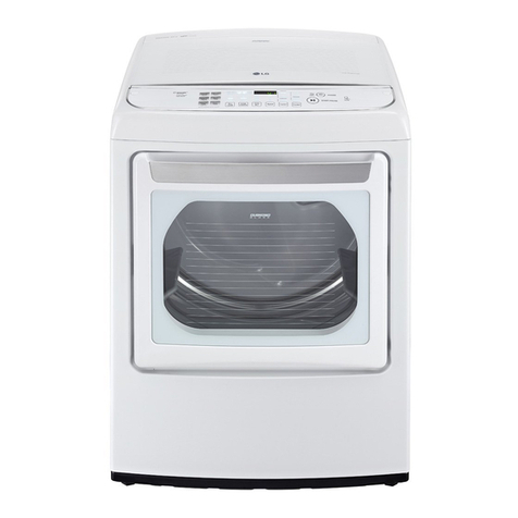
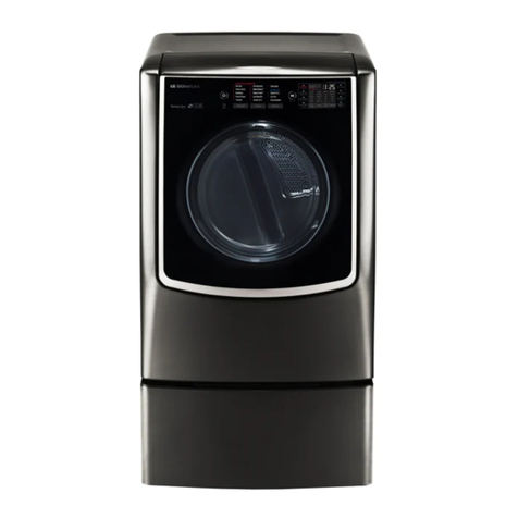
LG TCD1870QGS User manual

GAS DRYER
SERVICE MANUAL
CAUTION
READ THIS MANUAL CAREFULLY IN ORDER TO
PROPERLY DIAGNOSE PROBLEMS AND TO SAFELY
PROVIDE QUALITY SERVICE ON THESE DRYERS.
MODEL : TCD1870QGS
TCD1870CGS
TCD1870QGG
TCD1870CGG
Any reproduction, duplication, distribution (including by way of email, facsimile or other electronic means), publication,
modication, copying or transmission of this Service Manual is STRICTLY PROHIBITED unless you have obtained the
prior written consent of the LG Electronics entity from which you received this Service Manual. The material covered by
this prohibition includes, without limitation, any text, graphics or logos in this Service Manual.
Copyright © 2014 - 2017 LG Electronics Inc. All rights reserved. Only training and service purposes.
CONFIDENTIAL

CONTENTS
2
1. IMPORTANT SAFETY INSTRUCTIONS .................................................................................... 4
2. SPECIFICATIONS ................................................................................................................... 10
3. FEATURES AND BENEFITS ................................................................................................... 12
4. INITIAL STEPS FOR INSTALLING YOUR DRYER ................................................................... 14
5. DEBIT SYSTEM INSTALLATION INSTRUCTIONS .................................................................. 21
6. ELECTRICAL REQUIREMENTS FOR GAS DRYERS .............................................................. 23
7. GAS REQUIREMENTS AND INSTRUCTIONS ........................................................................ 24
8. EXHAUST REQUIREMENTS AND MAINTENANCE................................................................. 25
9. DRYER CYCLE PROCESS ...................................................................................................... 29
10. COMPONENT TESTING INFORMATION ............................................................................. 30
11. MOTOR DIAGRAM AND SCHEMATIC.................................................................................. 31
12. CONTROL LAY - OUT .......................................................................................................... 32
13. WIRING DIAGRAM................................................................................................................ 34
14. DIAGNOSTIC TEST ............................................................................................................... 35
15. ERROR MODE ...................................................................................................................... 42
16. CHANGE GAS SETTING (NATURAL GAS, PROPANE GAS) ............................................... 43
17. DISASSEMBLY INSTRUCTIONS .......................................................................................... 47
18. EXPLODED VIEW ................................................................................................................. 56
18-1-1. Control Panel & Cabinet & Cabinet Cover Assembly - Single Card &OPL Type....... 56
18-1-2. Control Panel & Cabinet & Cabinet Cover Assembly - Single Coin Type................. 57
18-1-3. Control Panel & Cabinet & Cabinet Cover Assembly - Stack Card &OPL Type_Lower ...... 58
18-1-4. Control Panel & Cabinet & Cabinet Cover Assembly - Stack Card &OPL Type_Upper...... 59
18-1-5. Control Panel & Cabinet & Cabinet Cover Assembly - Stack Coin Type_Lower ...... 60
18-1-6. Control Panel & Cabinet & Cabinet Cover Assembly - Stack Coin Type_Upper...... 61
18-2. Drum &Motor Assembly ............................................................................................... 62
18-3. Case Assembly ............................................................................................................ 63
19. PCB PICTURE ....................................................................................................................... 64
19-1. PCB Layout (Main) ....................................................................................................... 64
19-2. PCB Layout (Sub) ......................................................................................................... 65
Copyright © 2014 - 2017 LG Electronics Inc. All rights
reserved. Only training and service purposes.

3
FOR YOUR SAFETY
Do not store or use gasoline or other ammable vapors and liquids in the vicinity of
this or any other appliance.
POUR VOTRE SÉCURITÉ
Ne pas entreposer ni utiliser d’essence ni d’autres vapeurs ou liquids inammables à
proximité de cet appareil ou de tout autre appareil.
AVERTISSEMENT : Assurez-vous de bien suivre les instructions données dans cette
notice pour réduire au minimum le risqué d’incendie our d’explosion ou pour éviter
tout dommage matériel, toute blessure ou la mort.
– Ne pas entreposer ni utiliser d’essence ni d’autres vapeurs ou liquids inammables à
proximité de cet appareil ou de tout autre appareil.
– QUE FAIR SE VOUS SENTEZ UNE ODEUR DE GAZ:
Ne pas tenter d’allumer d’appareils.
Ne touchez à aucun interrupteur. Ne pas vous server des téléphones se trouvant
dans la bâtiment.
Évacuez la pièce, le bâtiment ou la zone.
Appelez immédiatement votre fournisseur de gaz depuis un voisin.
Suivez les instructions du fournisseur.
Si vous ne pouvez rejoindre le fournisseur de gaz, appelez le service des incendies.
– L’installation et l’entretien doivent être assurés par un installateur ou un service
d’entretien qualié ou par le fournisseur de gaz.
Caution: Label all wires prior to disconnection when servicing controls. Wiring errors
can cause improper operation.
Note :Purchaser shall post in a prominent location instructions to be Followed in the
event the user smells gas. The information to be posted shall be obtained by
consulting with the local gas supplier.
Attention: Au moment de l’entretien des commandes, étiquetez tous les ls avant de les
débrancher. Des erreurs de câblage peuvent entraîner un fonctionnement inadéquat.
Warning : For your safety the information in this manual must be followed to mini-
mize the risk of fire or explosion or to prevent property damage, personal injury or
death.
– Do not store or use gasoline or other flammable vapors and liquids in the vicinity of
this or any other appliance.
– WHAT TO DO IF YOU SMELL GAS
• Do not try to light any appliance.
• Do not touch any electrical switch; do not use any phone in your building.
• Clear the room, building or area of all occupants.
• Immediately call your gas supplier from a neighbor’s phone. Follow the gas suppli-
er’s instructions.
• If you cannot reach your gas supplier, call the fire department.
– Installation and service must be performed by a qualified installer, service agency
or the gas supplier.
4
1IMPORTANT SAFETY INSTRUCTIONS
RECONNECT ALL GROUNDING DEVICES
Use an anti-static wrist strap. Connect wrist strap to green ground connection point or unpainted
metal in the appliance.
Before removing the part from its package, touch the anti-static bag to a green ground connection
point or unpainted matal in the appliance.
Avoid touching electronic parts or terminal contacts, Handle electronic control assembly by edges
only.
Observe above instructions when repackaging failed electronic control seembly in an anti-static
bag.
- OR -
ESD problems are present everywhere. ESD may damage or weaken the electronic
control assembly. The new control assembly may appear to work well after repair
is finished, but failure may occur at a later date due to ESD stress.
Touch your finger repeatedly to a green ground connection point or unpainted
metal in the appliance.
If grounding wires, screws, straps, clips, nuts or washers used to complete a path to ground are
removed for service, they must be returned to their original position and properly fastened.

5

6

7

8

9
{GwGGGGGGzGGjGGGGGGGGGGUG
~GGGU

1SPECIFICATIONS
10
■Type : Gas Dryer
■Rating : Please refer to the rating label regarding detailed information.
■Single dryer size : 737mm (W)x 1090mm (D)x 1022mm (H)
29in (W)x 4215/16in (D)x 401/4in (H)
■Stack dryer size : 737mm(W) x 1090mm(D) x 2040mm(H)
29in (W)x 4215/16in (D)x 805/16in (H)
■Gas Dryer Max capacity : IEC 9.0 cu.ft.(30lb)
■Weight : Side by side - 220lbs(100kg)
Stackt - 440lbs (200kg)
※Specifications are subject to change by manufacturer.
※Stack model is double(Max capacity,weight)
2SPECIFICATIONS

11
ITEM
TCD1870CGS (single)
TCD1870CGS (single)
TCD1870CGG (stack)
TCD1870CGS (stack)
REMARK
TYPE Gas
POWER SUPPLY 120V/60Hz
MATERIAL &
FINISH
Color Silver stone
Top plate Porcelain (Single Model)
Painted &Porcelain (Stack Model)
Door Trim Stainless Deco
Door frame Chrom (Hairline)
C/Panel Color Silver stone
ELECTRICITY
CONSUMPTION
Drum Motor 385W Stack is double
BLDC Fan Motor 300W Stack is double
Ignition controller 4VA Stack is double
CONTROL TYPE Electric
DRUM CAPACITY 13.6kg (30lb) Stack is double
GAS PRESSURE 5,0 ~ 10,5" w,c, (10~13" w,c,)
BURNER PRESSURE 3.8"w.c.(8.67"w.c.) Natural (Propane)
NOMINAL HEAT INPUT 55,000Btu/hr Stack is double
Product
(W x D x H)
Single 737mm x 1090mm x 1022mm
Stack 737mm x 1090mm x 2040mm
Packing
(W x D x H)
Single 797mm x 1140mm x 1215mm
Stack 797mm x 1140mm x 2250mm

1SPECIFICATIONS
12
3FEATURES AND BENEFITS
1. DISPLAY LED
2. CYCLE BUTTON
3. START BUTTON
4. STATUS LED
■COIN/OPL TYPE
- SIDE BY SIDE(TCD1870CGS)
■ STACK (TCD1870CGG)
- UPPER
- LOWER
1
4
3
2
1
4
3
2
1
4
3
2
1
4
3
2
1
4
3
2
1
4
3
2
1 3
4 2
1 3
4 2
1 3
4 2
1 3
4 2
1 3
4 2
1 3
4 2
1
4
3
2
1
4
3
2
1
4
3
2
1
4
3
2
1
4
3
2
1
4
3
2
1 3
4 2
1 3
4 2
1 3
4 2
1 3
4 2
1 3
4 2
1 3
4 2
1
4
3
2
1
4
3
2
1
4
3
2
1
4
3
2
1
4
3
2
1
4
3
2
1 3
4 2
1 3
4 2
1 3
4 2
1 3
4 2
1 3
4 2
1 3
4 2

13
1. DISPLAY LED
2. CYCLE BUTTON
3. START BUTTON
4. STATUS LED
■ COIN TYPE
- SIDE BY SIDE(TCD1870QGS)
1
4
3
2
1
4
3
2
1
4
3
2
1
4
3
2
1
4
3
2
1
4
3
2
1 3
4 2
1 3
4 2
1 3
4 2
1 3
4 2
1 3
4 2
1 3
4 2
1
4
3
2
1
4
3
2
1
4
3
2
1
4
3
2
1
4
3
2
1
4
3
2
1 3
4 2
1 3
4 2
1 3
4 2
1 3
4 2
1 3
4 2
1 3
4 2
1
4
3
2
1
4
3
2
1
4
3
2
1
4
3
2
1
4
3
2
1
4
3
2
1 3
4 2
1 3
4 2
1 3
4 2
1 3
4 2
1 3
4 2
1 3
4 2
■ STACK (TCD1870QGG)
- UPPER
- LOWER

14
4
INITIAL STEPS FOR INSTALLING YOUR DRYER

15
{GGGGGGGG
SGGGGUG{ G¡G
SGSGGGSGG
GGGGGSGGUG
uv{laGhGGGGGGGG
GGGGUGlGG
GGGGGGGG
GGGU
~hyupunG
G
|GGGGGGG
GGGUG{ GGG
GGGGGGGG
yGGGGGGGG
GGGGGGGGU
tGGGG[GGGGG
GGGU
GhGG GGG GGG G
U GnG GG G G G GG
G GG GG G G GGG
GGGGU G
pGGG GGGGGG
SGG G G G G G G G
GGGGU G{GG GG
GGGU
Leveling Feet
wGGGGGGUGwG
GGGGGGGUG
G
z{lwGYG
LEVELING the Dryer.

16
z{lwGZG
Procedure for Reversing
the Door
Door and latch should be aligned at the center
when closed. Otherwise, the door will not open,
lose, or latch properly.

z{lwG[G
Connecting the Exhaust
and Venting System.
The dryer must be installed wih a proper exhaus
t
duct connection to the outside.
The dryer must be installed with provisions for
adequate combustion and make-up air supply.
17

18
z{lwG\G
Connection of Gas Supply
z{lwG]G
Electrical Plug Connection

19
!
!
z{lwG^G
Preparation of the Dryer
z{lwG`G
Dryer Airflow
z{lwG_G
Confirming Heat Source
Operation

20
* [LGTGG|UzUGGGXWWWGUGGU
* XWLTGGjGGGGYWWWT[\WWGUG GG
G [LGGGGXWWWGU
* Heating Value [Btu/ft3 ] ˧LNG:1017,LPG:2573
High Altitude Burner Orifice Sizing
Other manuals for TCD1870QGS
1
This manual suits for next models
3
Table of contents
Other LG Dryer manuals

LG
LG DLE7000 Series User manual

LG
LG DLE3777 User manual

LG
LG Steam Dryer DLGX2551 Series User manual

LG
LG DLEX7300 E Series User manual

LG
LG DLEX89 0 Series User manual

LG
LG DLEX9000 Series User manual

LG
LG RC8084 V W Series User manual

LG
LG DF22BV2B User manual

LG
LG DLE2140 Series User manual

LG
LG DLEX7700*E User manual
Popular Dryer manuals by other brands

Electrolux
Electrolux EDH 97941 W user manual

Dolphin
Dolphin BC 2003BM user manual

Zanussi
Zanussi TD 101/A Instructions for use and care

Alliance Laundry Systems
Alliance Laundry Systems LTZ87A*H0902 Series installation instructions

Dyson
Dyson Airblade AB06 owner's manual

Electrolux
Electrolux EFLS210TIW Use & care guide