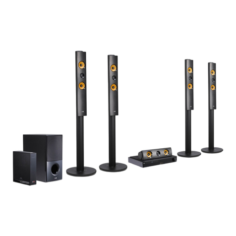
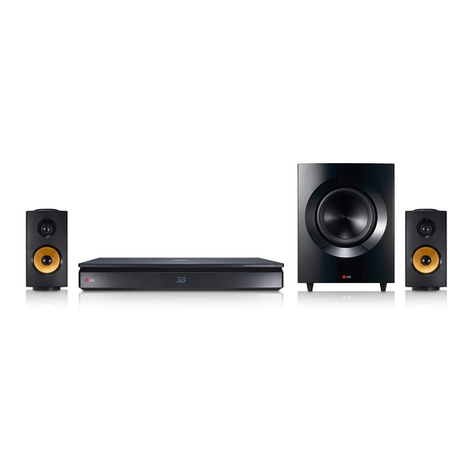
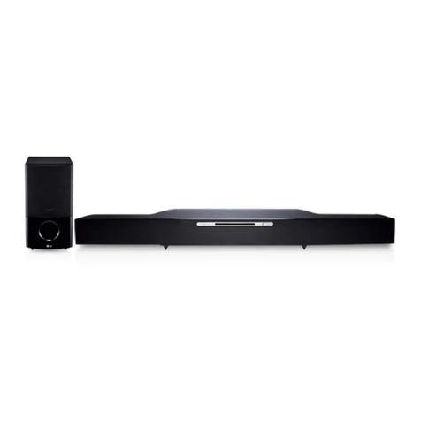
LG LHT754 - Home Theater System Installation guide

LG TRAINING MANUAL
LHT754 Home Theater - Fall 2007

1
Published August 2007 by LG Education & Product Engineering
Customer Service (and Part Sales): 1-800-243-0000
Technical Support (and Part Sales): 1-800-847-7597
USA Website: www.lgusa.com
Customer Service Website: us.lgservice.com
B2B Service Website: aic.lgservice.com
Training Website: www.LGCSAcademy.com
IMPORTANT SAFETY NOTICE
This manual was prepared for use only by properly trained audio-visual service technicians. When servicing this product, under no circumstances
should the original design be modified or altered without permission from LG Electronics. Unauthorized modifications will not only void the warranty,
but may lead to property damage or user injury. All components should be replaced only with types identical to those in the original circuit and
their physical location, wiring, and lead dress must conform to original layout upon completion of repairs. If any fuse (or Fusible Resistor) in this TV
receiver is blown, replace it only with the factory specified fuse type and rating. When replacing a high wattage resistor (Oxide Metal Film Resistor,
over 1W), keep the resistor 10mm away from PCB. Always keep wires away from high voltage or high temperature parts. Do not attempt to modify
this product in any way.
Special components are also used to prevent shock and fire hazard and are required to maintain safe performance. No deviations are allowed without
prior approval by LG Electronics. Service work should be performed only after you are thoroughly familiar with these safety checks and servicing
guidelines. Circuit diagrams may occasionally differ from the actual circuit used. This way, implementation of the latest safety and performance
improvement changes into the set is not delayed until the new service literature is printed.
GENERAl SAFETY GuIdANCE
An lsolation Transformer should always be used during the servicing of a receiver whose chassis is not isolated from the AC power line. Use a
transformer of adequate power rating to protect against personal injury from electrical shocks. It will also protect the receiver and its components
from being damaged by accidental shorts of the circuitry that may be inadvertently introduced during the service operation. Before returning the
receiver to the customer, always perform an AC leakage current check on the exposed metallic parts of the cabinet, such as antennas, terminals,
etc., to be sure the set is safe to operate without damage of electrical shock.
With the instrument AC plug removed from AC source, connect an electrical jumper across the two AC plug prongs. Place the AC switch in the on
position, connect one lead of ohm-meter to the AC plug prongs tied together and touch other ohm-meter lead in turn to each exposed metallic
parts such as antenna terminals, phone jacks, etc. If the exposed metallic part has a return path to the chassis, the measured resistance should
be between 1MΩand 5.2MΩ. When the exposed metal has no return path to the chassis the reading must be infinite. Any other abnormality that
exists must be corrected before the receiver is returned to the customer.
ElECTROSTATICAllY SENSITIvE dEvICES
Some semiconductor (solid-state) devices can be damaged easily by static electricity. Such components commonly are called Electrostatically Sensi-
tive (ES) Devices. Examples of typical ES devices are integrated circuits and some field-effect transistors and semiconductor “chip” components. The
following techniques should be used to help reduce the incidence of component damage caused by static electricity.
Immediately before handling any semiconductor component or semiconductor-equipped assembly, drain off any electrostatic charge on the body by
touching a known earth ground. Alternatively, obtain and wear a commercially available discharging wrist strap device, which should be removed for
potential shock reasons prior to applying power to the unit under test. After removing an electrical assembly equipped with ES devices, place the
assembly on a conductive surface such as an ESD mat, to prevent electrostatic charge buildup or exposure of the assembly. Use only a grounded-tip
soldering iron to solder or unsolder ES devices. Use only an anti-static solder removal device. Some solder removal devices not classified as “anti-
static” can generate electrical charges sufficient to damage ES devices. Do not use freon-propelled chemicals which can generate electrical charge
sufficient to damage ES devices. Do not remove a replacement ES device from its protective package until immediately before you are ready to install
it. Minimize bodily motions when handling unpackaged replacement ES devices (Otherwise, seemingly harmless motion, such as the brushing together
of your clothing or the lifting of your foot from a carpeted floor, can generate static electricity sufficient to damage an ES device).
REGulATORY INFORMATION
This equipment has been tested and found to comply with the limits for a Class B digital device, pursuant to Part 15 of the FCC Rules. These limits
are designed to provide reasonable protection against harmful interference when the equipment is operated in a residential installation. This equip-
ment generates, uses and can radiate radio frequency energy and, if not installed and used in accordance with the instruction manual, may cause
harmful interference to radio communications. However, there is no guarantee that interference will not occur in a particular installation. If this
equipment does cause harmful interference to radio or television reception, which can be determined by turning the equipment off and on, the
user is encouraged to try to correct the interference by one or more of the following measures: Reorient or relocate the receiving antenna; Increase
the separation between the equipment and receiver; Connect the equipment into an outlet on a circuit different from that to which the receiver is
connected; Consult the dealer or an experienced radio/TV technician for help.
The responsible party for this device’s compliance is:
LG Electronics of Alabama, Inc.
201 James Record Road
Huntsville, AL 35824, USA
Digital TV Hotline: 1-800-243-0000

LHT 754 Home Theater in a Box Training Contents
Table of conTenTs
2
SPECIFICATIONS .................................................................................................................2
OPERATION ..........................................................................................................................5
FRONT PANEL/REAR PANEL .................................................................................5
REMOTE CONTOL ..................................................................................................6
INSTALLATION AND SETUP ...................................................................................7
HDMI CONNECTION .............................................................................................10
LANGUAGE MENU ................................................................................................12
DISPLAY MENU .....................................................................................................13
AUDIO MENU .........................................................................................................14
LOCK ......................................................................................................................17
OTHERS .................................................................................................................18
CIRCUIT DESCRIPTIONS ...................................................................................................19
MAIN BLOCK DIAGRAM ........................................................................................19
POWER KEY CIRCUIT DIAGRAM .........................................................................20
SMPS (POWER) CIRCUIT DIAGRAM ....................................................................21
POWER INTERFACE CIRCUIT DIAGRAM ............................................................22
MAIN MICOM CIRCUIT DIAGRAM .........................................................................23
SERVO CIRCUIT DIAGRAM ...................................................................................24
I/O SECTION DIAGRAM .........................................................................................25
MIC/USB/PTB CIRCUIT ..........................................................................................26
TIMER CIRCUIT DIAGRAM ....................................................................................27
HDMI CIRCUIT DIAGRAM ......................................................................................28
XM READY CIRCUIT DIAGRAM .............................................................................29
MPEG CIRCUIT DIAGRAM .....................................................................................30
DSP CIRCUIT DIAGRAM ........................................................................................31
AMP CIRCUIT DIAGRAM ........................................................................................32
WAVEFORMS ..........................................................................................................33
TROUBLESHOOTING ...........................................................................................................46
POWER SUPPLY .....................................................................................................46
FRONT CIRCUIT (1/2) .............................................................................................47
FRONT CIRCUIT (2/2) .............................................................................................48
AMP PROTECTION .................................................................................................49
SYSTEM OPERATION FLOW .................................................................................50
TEST & DEBUG .......................................................................................................51
AUDIO MICOM CIRCUIT (DVD &) ..................................................................57
DISASSEMBLY .....................................................................................................................58
WIRING DIAGRAM ..................................................................................................58
EXPLODED VIEW (MAIN FRAME) .........................................................................59
EXPLODED VIEW (DECK MECHANISM) ...............................................................60

LHT 754 Home Theater in a Box Training Contents
specificaTions
3
GENERAL
Power supply Refer to main label
Power consumption Refer to main label
Net Weight 3.9 kg
External dimensions (W x H x D) 430 x 70 x 310 mm
Operating conditions Temperature: 5°C to 35°C, Operation status: Horizontal
Operating humidity 5% to 85%
CD/DVD
Laser Semiconductor laser, wavelength 650 nm
Signal system NTSC 525/60
Frequency response (audio) 200 Hz to 18 kHz
Signal-to-noise ratio (audio) More than 75 dB (1 kHz, NOP-6 dB, 20 kHz LPF/A-Filter)
Dynamic range (audio) More than 70 dB
Harmonic distortion (audio) 0.5 % (1 kHz, at 1W position) (20 kHz LPF
VIDEO
Video input 1.0 V (p-p), 75 Ω, negative sync., RCA jack x 1
Video output 1.0 V (p-p), 75 Ω, negative sync., RCA jack x 1
Component video out (Y) 1.0 V (p-p), 75Ω, negative sync, RCA jack x 1(Pb)/(Pr)
0.7V(p-p), 75Ω, RCA jack x 1
TUNER
FM
Tuning Range 87.5 - 108.0 MHz or 65.0 - 74.0 MHz, 87.5 - 108.0 MHz
Intermediate Frequency 10.7 MHz
Signal-to Noise Ratio 60 dB (Mono)
Frequency Response 140 - 8,000 Hz
AM [MW]
Tuning Range 522 - 1,620 kHz or 520 - 1,720 kHz
Intermediate Frequency 450 kHz
AMPLIFIER
Stereo mode 155W + 155W (4Ωat 1kHz, THD 10%)
Surround mode Front: 155W + 155W (THD 10 %)
Centre*: 155W
Surround*: 155W + 155W (4Ωat 1 kHz, THD 10 %)
Subwoofer*: 225W (3Ωat 30 Hz, THD 10 %)
Inputs AV IN, OPTICALIN
Outputs MONITOR OUT, HDMI OUTCOMPONENTVIDEO OUT

4
LHT 754 Home Theater in a Box Training Specications
specificaTions
SPEAKERS
Front/Rear Speaker Center speaker Passive Sub-
woofer
(SH92SB-S) (SH92SB-C) (SH92SB-
W)
Type 1 Way 1 Speaker 2 Way 3 Speaker 1 Way 1
Speaker
Impedance 4 Ω 4 Ω 3 Ω
Frequency Response 120 - 18000 Hz 80 -18000 Hz 40 - 1500
Hz
Sound Pressure Level 83 dB/W (1m) 83 dB/W (1m) 82 dB/W
(1m)
Rated Input Power 155 W 155 W 225 W
Max. Input Power 310 W 310 W 450 W
Net Dimensions (W x H x D) 113 x 209 x 83 mm 450 x 161 x 102 mm 258 x 440
x 401 mm
Net Weight 0.83 kg 1.8 kg 6.8
kg

LHT 754 Home Theater in a Box Training Operation
operaTion
5
Front Panel/Rear Panel

6
LHT 754 Home Theater in a Box Training Operation
operaTion
Remote Control
Remote Control
OPEN/CLOSE (Z)
Opens and closes the disc tray.
DVD
Selects the output source (CD/DVD).
iPod
Selects the iPod source.
S-TITLE
Selects a subtitle language (DVD).
CLEAR
Removes a track number on the
program menu or a mark on the
MARKER SEARCH menu.
MARKER
Marks a point during playback.
SEARCH
Displays MARKER SEARCH menu.
SCAN/SLOW(bb/BB)
Searches backward or forward.
Reverse/Forward slow playback.
REVERSE/FORWARD SKIP
(./>)
TITLE
Displays the disc’s Title menu, if
available.
STOP (x), PLAY (B)
PAUSE/STEP (X)
VSM
XTS pro
Supplies more natural and realistic
sound.
Supplies great sound effect.
SLEEP
Sets the System to turn off
automatically at a specified time.
MUTE
VOLUME (-/+)
Adjusts speaker volume.
XM MODE
Selects a XM display mode.
RESOL.
Changes the resolution depending on
your TV.
PROG./MEMO.
Accesses or removes Program menu.
Enter a radio station’s frequency into
the tuner.
TV Control Buttons
- POWER: Switches TV ON and
OFF.
- CHANNEL v/V:Selects TV’s
channel.
- VOLUME +/–: Adjusts TV’s
volume.
- INPUT: Selects the TV’s source.
TUNER
AUX
USB
AUDIO
OPEN/CLOSE
SOUND S-TITLE CLEAR
MENU
SLEEP
XM CH XM CH
MUTE
POWER
INPUT
CHANNEL VOL
CAT/HDMI
XM MODE/RESOL.
ZOOM
SETUP
ENTER
DISPLAY
RETURN
VOL
SCAN +
SKIP SCAN +
TITLE
STOP PLAY
REPEAT
REPEAT A-B
MARKER SEARCH
DVD
iPod
POWER
DIMMER
PAUSE/STEP
PROG./MEMO.
POWER
TUNER
Selects the System’s tuner (FM ,AM and
XM bands).
AUX
Selects input source.
USB
Plays the multimedia files.
DIMMER
Changes brightness of the display
window on the front panel during in
power-on status.
AUDIO
Selects an audio language (DVD) or an
audio channel (CD).
SOUND
Selects the sound mode.
REPEAT
Repeats chapter, track, title, all
REPEAT A-B
Repeats sequence.
MENU
Accesses the menu on a DVD disc.
ZOOM
SETUP
Accesses or removes setup menu.
DISPLAY
Accesses On-Screen display.
RETURN
Removes the setup menu.
b/B/v/V(left/right/up/down)
Selects an option in the menu.
ENTER
Acknowledges the menu selection.
PRESET (-/+)
Selects programme of Radio.
XM CH (-/+)
Tunes in the desired XM station.
TUN. (-/+)
Tunes in the desired radio station.
0-9 numerical buttons
Selects a service, program number
directly or selects numbered options in
a menu.
CAT
Selects the Category Search.
HDMI
Switches the HDMI mode to HDMI
(active) and OFF (inactive).

LHT 754 Home Theater in a Box Training Operation
operaTion
7
Installation and Setup
Rear of DVD/CD Receiver
Video connection
Connect the MONITOR OUT jack from the DVD/CD Receiver to the VIDEO IN jack on the TV using
the video cable supplied (V).
Component Video (Color Stream®) connection
Connect the COMPONENT VIDEO OUT jacks from the DVD/CD Receiver to the corresponding
jacks on the TV using a Y PB PR cable (C).
USB connection (U)
Connect the USB port of USB Memory (or MP3player, etc.) to the USB port on the front of the unit.

8
LHT 754 Home Theater in a Box Training Operation
operaTion
Removing the USB Device from the unit
1. Choose a different function mode or press STOP(x) twice in a row.
2. Remove the USB device from the unit.
AUX IN connection (A)
Connect an Output of auxiliary device to the AUX
AUDIO Input (L/R) Connector.
OPTICAL IN connection (O)
Connect an optical output of DVD Player (or Digital Device etc) to the OPTICAL IN connector.
AUDIO IN connection (D)
Connect a output of portable device (MP3 or PMPetc)to the AUDIO input connector.
iPod Connection
Connect the iPod connector on the rear of the DVD/CD Receiver to the dock connector of iPod
using an iPod cable (I).

LHT 754 Home Theater in a Box Training Operation
operaTion
9
Antenna Connection
Connect the AM Loop antenna to the AM antenna connector.
Connect the FM Wire antenna to the FM antenna connector.
Speaker System Connection
Connect the speakers using the supplied speaker wires.

10
LHT 754 Home Theater in a Box Training Operation
operaTion
HDMI Connection
About HDMI
HDMI(HighDenitionMultimediaInterface)supportsbothvideoandaudioonasingledigitalconnec-
tion for an easy all- digital output to an HDMI or DI-equipped TV.
Connection to an HDMI TV requires an HDMI cable while connection to a DVI-equipped TV requires a
DVI adapter besides a HDMI cable.
HDMIhasthecapabilitytosupportstandard,enhanced,orhigh-denitionvideoplusstandardto
multi-channel surround-sound audio, HDMI features include uncompressed digital video, a bandwidth
of up to 5 gigabytes per second, one connector (instead of several cables and connector), and com-
munication between the AV source and AV devices such as DTVs.
HDMI,theHDMIlogoandHigh-DenitionMultimediaInterfacearetrademarksorregisteredtrade-
marks of HDMI licensing LLC.
If you have a HDMI TV or monitor, you can connect it to this DVD/CD Receiver using a HDMI cable.
1. Connect the HDMI OUT jack on the DVD/CD Receiver to the HDMI jack on a HDMI compatible TV
or monitor (H).
2. Set the TV’s source to HDMI (refer to owner’s manual for TV).
3. In the stop mode, select HDMI mode by pressing HDMI. Press RESOL. repeatedly to select the
resolution you wish to change.

LHT 754 Home Theater in a Box Training Operation
operaTion
11
Resolution setting
You can change the resolution for the COMPONENT VIDEO OUT by pressing RESOL.
on the Remote Control. Available resolution settings are as shown below.
Composite Video
The composite video output can only support the 480i format video resolution.
Component Video
The component (YPbPr) video output is capable of supporting 480i, 480p, 720p, and 1080i format
video resolutions. However, since component video is an analog connection and thus cannot sup-
port HDCP copy-protection, 480p, 720p, and 1080i are not available for DVD playback. Even if higher
formats are selection, the video output will automatically output at 480i during copy-protected DVD
playback
HDMI Out
The HDMI output supports 480p, 720p, 1080i format resolutions. DVD playback is limited to a maxi-
mum resolution of 1080i.

12
LHT 754 Home Theater in a Box Training Operation
operaTion
LANGUAGE MENU
OSD
Select a language for the Setup menu and then
on-screen display.
DISC AUDIO / SUBTITLE / MENU
Select the language you prefer for the audio track
(disc audio), subtitles, and the disc menu.
Original – Refers to the original language in which
the disc was recorded.
Other – To select another language, press
numeric buttons and then ENTER to enter the
corresponding 4-digit number. If you enter the
wrong language code, press CLEAR.

LHT 754 Home Theater in a Box Training Operation
operaTion
13
DISPLAY MENU
TV Aspect
4:3 - Select when a standard 4:3 TV is connected.
16:9 – Select when a 16:9 wide TV is connected.
Display Mode
The Display Mode setting works only when the TV
aspect mode is set to “4:3”.
Letterbox - Displays a wide picture with bands
on the upper and lower portions of the screen.
Panscan – Automatically displays the wide
picture on the entire screen and then cuts off
theportionsthatdonott.

14
LHT 754 Home Theater in a Box Training Operation
operaTion
AUDIO MENU
Each DVD disc has a variety of audio output options.
Set the receiver’sAUDIO options according to the type
of audio system you use.
Dynamic Range Control (DRC)
With the DVD *1 format, you can hear a program’s
soundtrack in the most accurate and realistic
presentation, thanks to digital audio technology.
However, you may wish to compress the dynamic
range of the audio output (the difference between the
loudest sounds and the quietest ones). Then, you may
listen to a movie at a lower volume without losing
clarity of sound. Set DRC to On for this effect.
*1:Dolby Digital only
Vocal
Set Vocal to On only when a multi-channel karaoke DVD is playing.
The karaoke channels on the disc will mix into normal stereo sound.
HD AV Sync
When using a Digital TV. Sometimes the AV signal can not
be transmitted simultaneously because of later transmission
of the video signal compared to the audio signal. It takes
some time to convert the analog video signal to a digital one in
the Digital TV. It also means that you may not enjoy the picture
on the screen and the sound from speakers at the same time
even though it is one scene. In the HD AV Sync menu,
you can adjust the delay time to the audio signal for simultaneous
AV signal transmission.
Delay time can be set up with 10msec unit. (0 ~ 300ms)
Delay time is different according to each TV Brand.
So you need to adjust optimal delay time to comply with your TV.

LHT 754 Home Theater in a Box Training Operation
operaTion
15
5.1 Speaker Setup
Make the following settings for the built-in 5.1 channel
surround decoder.
1.Press ENTER, and the 5.1 Speaker Setup menu appears.
2.Use b/B to select the desired speaker.
3.Adjust options using v/V/b/B buttons.
4.PressENTERtoconrmyourselection.Returnstothe
previous menu.
Speaker selection
Select a speaker that you want to adjust. [Front speaker (Front L),
Front speaker (Front R), Center Speaker (Center), Subwoofer
(SubWoofer), Rear speaker (Rear L), Rear speaker (Rear R)]
Size
Sincethespeakersettingsarexed,youcannotchangethesettings.

16
LHT 754 Home Theater in a Box Training Operation
operaTion
Volume
Press to adjust the output level of the selected speaker. (-5dB ~ 5dB)
Distance
If you connected speakers to your DVD/CD Receiver, setting
the Distance lets the speakers know how far the sound has
to travel to reach your set listening point. This allows the sound
from each speaker to reach the listener at the same time. Press
b/B to adjust the Distance of the selected speaker.
(You can’t adjust front / Woofer speakers)
Test
Press b/B to test the signals of each speaker. Adjust the volume to
match the volume of test signals memorized in the system.
FrontLeft(FrontL)→Center→FrontRight(FrontR)→RearRight(RearR)→
RearLeft(RearL)→SubWoofer

LHT 754 Home Theater in a Box Training Operation
operaTion
17
LOCK (Parental Control)
Rating
Blocks playback of rated DVDs based on their contents. Not all
discs are rated.
1.Select “Rating” on the LOCK menu then press .
2.To access the LOCK options, you must input the password you
have created. If you have not yet entered password, you are
prompted to do so. Input a password and press ENTER. Enter it again
and press ENTER to verify. If you make a mistake before pressing
ENTER, press CLEAR.
3.Select a rating from 1 to 8 using the buttons. Rating 1-8:
Rating one (1) has the most restrictions and rating eight (8) is the
least restrictive. Unlock: If you select unlock, parental control is not
active and the disc plays in full.
4.PressENTERtoconrmyourratingselection,thenpressSETUP
to exit the menu.
Password
You can enter or change password.
1.Select Password on the LOCK menu and then press .
2.Follow the step 2 as shown above (Rating).To change the password,
press ENTER when the “Change” or “New” option is highlighted. Input a
password and press ENTER. Enter it again and press ENTER to verify.
3.Press SETUP to exit the menu.
If you forget your password
If you forget your password, you can clear it using the following steps:
1.Press SETUP to display the Setup menu.
2.Input the 6-digit number “210499” and press ENTER. The password is cleared.
Area Code
Enter the code of the area whose standards were used to rate the
DVD video disc, based on the list on page 28.
1. Select “Area Code”
on the LOCK menu then press .
2. Follow step 2 as shown in the rating section.
3.Selecttherstcharacterusingbuttons.
4. Press and select the second character using buttons.
5.PressENTERtoconrmyourAreacodeselection.

18
LHT 754 Home Theater in a Box Training Operation
operaTion
OTHERS
DivX(R) Registration
We provide you the DivX®VOD (Video On Demand) registration code
that allows you to rent and purchase videos based on the DivX®VOD
service. For more information, visit www.divx.com/vod.
1. Select “DivX(R) Registration” option and then press .
2. Press ENTER while “Select” is selected and the registration code will
appear. Use the registration code to purchase or rent the videos from
DivX®VOD service at www.divx.com/vod. Follow the instructions and
download the video onto a disc for playback on this unit.
3. Press ENTER to exit.

LHT 754 Home Theater in a Box Training Circuit Descriptions
circuiT descripTions
19
CIRCUIT DESCRIPTIONS
MAIN BLOCK DIAGRAM
IC2K1
IC4D1
IC201
IC202
IC502 IC503 IC506 IC301
IC401
IP9009A
IC501
IC601
Other manuals for LHT754 - Home Theater System
2
Table of contents
Other LG Home Theater System manuals